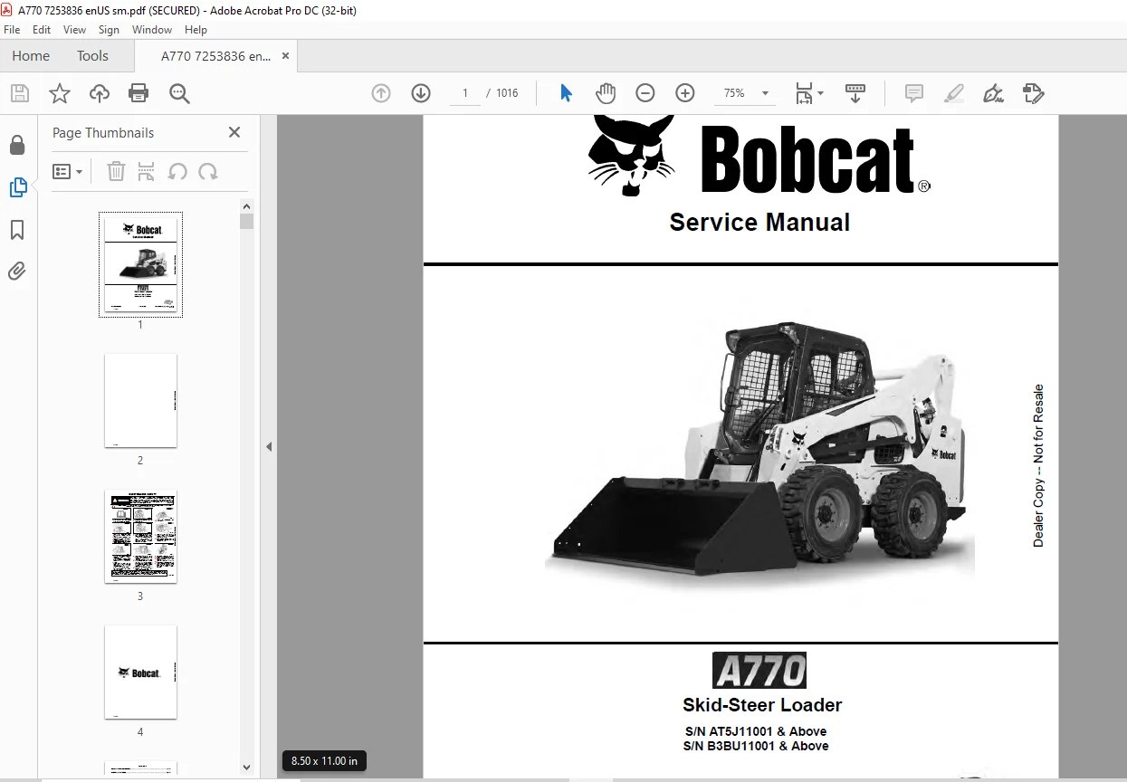
Bobcat A770 Skid-Steer Loader Service Manual 7253836 – PDF DOWNLOAD
$36.95
Bobcat A770 Skid-Steer Loader Service Manual 7253836 – PDF DOWNLOAD
Description
Bobcat A770 Skid-Steer Loader Service Manual 7253836 – PDF DOWNLOAD
FILE DETAILS:
Bobcat A770 Skid-Steer Loader Service Manual 7253836 – PDF DOWNLOAD
Language : English
Pages : 1016
Downloadable : Yes
File Type : PDF
IMAGES PREVIEW OF THE MANUAL:
DESCRIPTION:
Bobcat A770 Skid-Steer Loader Service Manual 7253836 – PDF DOWNLOAD
FOREWORD:
This manual is for the Bobcat loader mechanic. It provides necessary servicing and adjustment procedures for the Bobcat loader and its component parts and systems. Refer to the Operation & Maintenance Manual for operating instructions, starting procedure, daily checks, etc.
SAFETY INSTRUCTIONS:
The following publications provide information on the safe use and maintenance of the Bobcat machine and attachments:
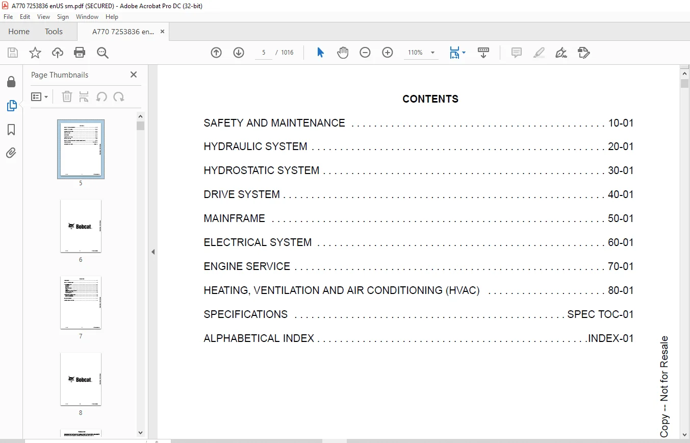
TABLE OF CONTENTS:
Bobcat A770 Skid-Steer Loader Service Manual 7253836 – PDF DOWNLOAD
MAINTENANCE SAFETY 3
CONTENTS 5
FOREWORD 7
FOREWORD 9
SAFETY INSTRUCTIONS 11
FIRE PREVENTION 13
Maintenance 13
Operation 13
Electrical 13
Hydraulic System 13
Fueling 13
Starting 13
Spark Arrester Exhaust System 13
Welding And Grinding 14
Fire Extinguishers 14
SERIAL NUMBER LOCATIONS 15
Loader Serial Number 15
Engine Serial Number 15
DELIVERY REPORT 16
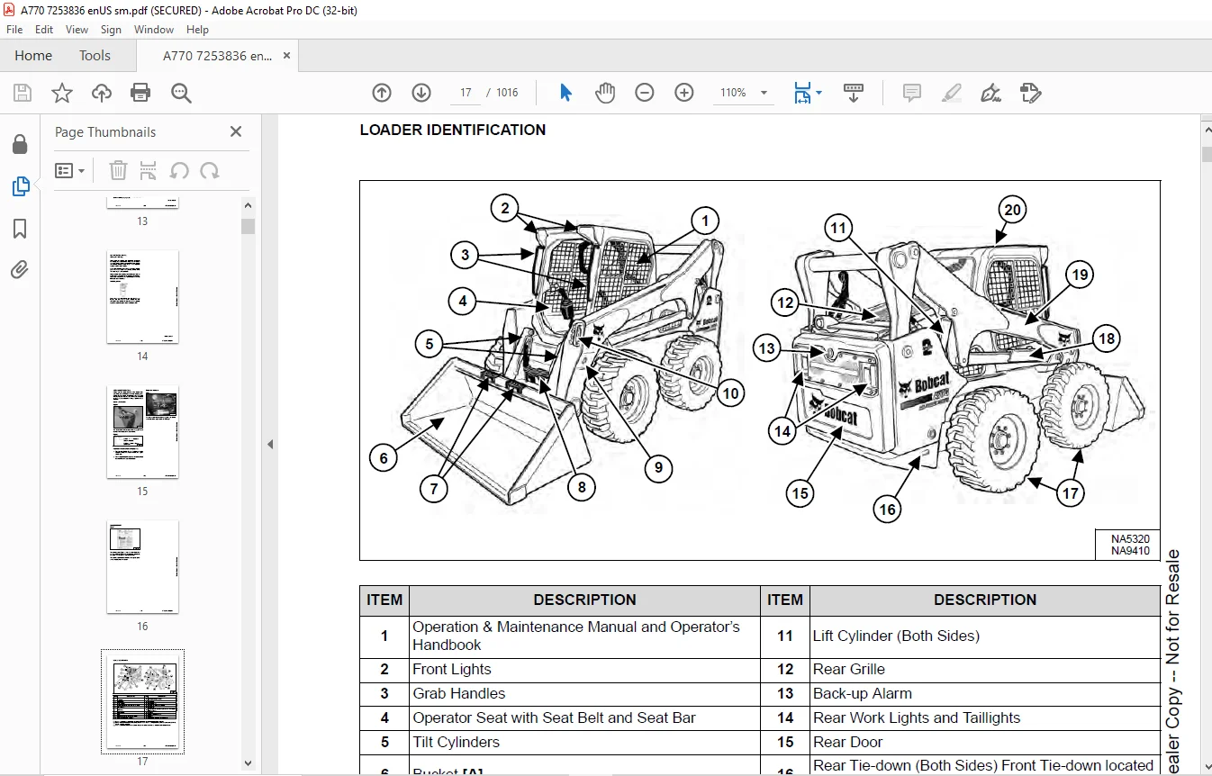
LOADER IDENTIFICATION 17
SAFETY AND MAINTENANCE 19
LIFTING AND BLOCKING THE LOADER 23
Procedure 23
LIFT ARM SUPPORT DEVICE 25
Description 25
Installing 26
Removing 27
OPERATOR CAB 29
Description 29
Raising 30
Lowering 31
Cab Door Sensor 32
Special Applications Kit 33
Special Applications Kit Inspection And Maintenance 33
Forestry Door And Window Kit 34
Forestry Door And Window Kit Inspection And Maintenance 34
TRANSPORTING THE LOADER ON A TRAILER 35
Loading And Unloading 35
Fastening 35
TOWING THE LOADER 37
Procedure 37
REMOTE START TOOL KIT – MEL1563 39
Remote Start Tool – MEL1563 39
Service Tool Harness Communicator – MEL1566 41
Remote Start Procedure 41
REMOTE START TOOL (SERVICE TOOL) KIT – 7217666 45
Description 45
Remote Start Tool (Service Tool) – 7022042 46
Loader Service Tool Harness – 6689747 47
Computer Service Tool Harness – 6689746 48
Remote Start Procedure 49
SERVICE SCHEDULE 53
Maintenance Intervals 53
ENGINE AIR CLEANER 55
Replacing Filters 55
ENGINE COOLING SYSTEM 57
Maintenance Platform 57
Cleaning 57
Checking And Adding Coolant 60
Removing And Replacing Coolant 61
FUEL SYSTEM 63
Fuel Specifications 63
Biodiesel Blend Fuel 63
Filling The Fuel Tank 64
Fuel Filter 65
Removing Air From The Fuel System 66
DIESEL EXHAUST FLUID (DEF) / ADBLUE® SYSTEM 67
Description 67
Filling The DEF / AdBlue® Tank 67
ENGINE LUBRICATION SYSTEM 69
Checking And Adding Engine Oil 69
Engine Oil Chart 69
Removing And Replacing Oil And Filter 70
HYDRAULIC / HYDROSTATIC SYSTEM 73
Checking And Adding Fluid 73
Hydraulic / Hydrostatic Fluid Chart 73
Removing And Replacing Hydraulic Fluid 74
Removing And Replacing Hydraulic / Hydrostatic Filter 76
Removing And Replacing Steering Filter 77
Removing And Replacing Hydraulic Charge Filter 78
Replacing Reservoir Breather Cap 79
FINAL DRIVE TRANSMISSION (CHAINCASE) 81
Checking And Adding Fluid 81
Removing And Replacing Fluid 81
BOB-TACH (HAND LEVER) 83
Inspection And Maintenance 83
BOB-TACH (POWER) 85
Inspection And Maintenance 85
LUBRICATING THE LOADER 87
Lubrication Locations 87
TIRE MAINTENANCE 91
Wheel Nuts 91
Rotating 91
Mounting 92
PIVOT PINS 93
Inspection And Maintenance 93
LOADER STORAGE AND RETURN TO SERVICE 95
Storage 95
Return To Service 95
STOPPING THE ENGINE AND LEAVING THE LOADER 97
Procedure 97
EMERGENCY EXIT 99
Rear Window Identification 99
Rear Window Removal (Latches) 99
Rear Window Removal (Rubber Cord) 99
External Access (Rear Window With Latches) 100
External Access (Rear Window With Rubber Cord) 100
Front Door 101
SEAT BELT 103
Inspection And Maintenance 103
HYDRAULIC SYSTEM 105
HYDRAULIC / HYDROSTATIC SCHEMATICS 109
HYDRAULIC SYSTEM INFORMATION 115
Glossary Of Hydraulic / Hydrostatic Symbols 115
Troubleshooting 119
CYLINDER (LIFT) 121
Testing 121
Removal And Installation 122
Parts Identification 125
Disassembly 126
Assembly 128
CYLINDER (TILT) 131
Testing 131
Removal And Installation 132
Base End Pivot Pin Removal And Installation 134
Parts Identification 135
Disassembly 136
Assembly 138
CYLINDER (BOB-TACH) 141
Testing 141
Removal And Installation 142
Parts Identification 143
Disassembly 144
Assembly 145
CYLINDER (STEERING) 149
Testing 149
Removal And Installation (Front) 151
Removal And Installation (Rear) 154
Parts Identification 157
Disassembly 158
Assembly 159
MAIN RELIEF VALVE 163
Description 163
Testing 164
Main Relief Valve Adjustment 166
Main Relief Valve Removal And Installation 166
Auxiliary Relief Valve Adjustment 167
Auxiliary Relief Valve Removal And Installation 168
HYDRAULIC CONTROL VALVE 169
Description 169
Removal And Installation 169
Actuator Removal And Installation (In Loader) 174
Actuator Removal And Installation (Out Of Loader) 175
Identification Chart 178
Mount Bracket Removal And Installation 179
Lift Load Check Valve Removal And Installation 179
Load Check Valve Removal And Installation (Tilt And Auxiliary) 180
Anti-Cavitation Valve Removal And Installation (Lift, Rod End) 181
Port Relief / Anti-Cavitation Valve Removal And Installation (Lift, Base End) 181
Port Relief / Anti-Cavitation Valve Removal And Installation (Tilt, Base End) 182
Port Relief / Anti-Cavitation Valve Removal And Installation (Tilt, Rod End) 182
Port Relief Valve Removal And Installation 183
Plug Removal And Installation 185
End Cap Block Removal And Installation 186
Lift Spool Removal And Installation 186
Lift Spool Disassembly And Assembly 188
Tilt Spool Removal And Installation 189
Auxiliary Spool Removal And Installation 191
Auxiliary Solenoid Removal And Installation 192
Solenoid Removal And Installation 193
Lock Valve Removal And Installation 194
Lift Arm Bypass Orifice Removal And Installation 196
Main Relief Valve Removal And Installation 196
Auxiliary Relief Valve Removal And Installation 197
Check Valve Removal And Installation 197
LIFT ARM BYPASS CONTROL VALVE 199
Description 199
Testing 199
Removal And Installation 200
Bracket Removal And Installation 201
Disassembly And Assembly 201
HYDRAULIC PUMP 203
Description 203
Pump Test At Quick Couplers 203
Direct Pump Test (Standard Section) 204
Direct Pump Test (Charge Section) 206
Direct Pump Test (Steering Section) 208
Removal And Installation 210
Hydraulic Pump Startup 212
Parts Identification 213
Disassembly And Assembly 214
HYDRAULIC PUMP (HIGH FLOW) 215
Description 215
Pump Test At Quick Couplers 215
Direct Pump Test (Standard Section) 216
Direct Pump Test (Charge Section) 217
Direct Pump Test (High Flow Section) 219
High Flow Relief Valve Adjustment 221
High Flow Relief Valve Removal And Installation 222
Direct Pump Test (Steering Section) 223
Solenoid Removal And Installation 225
Removal And Installation 226
Hydraulic Pump Startup 228
Parts Identification 229
Disassembly And Assembly 230
HYDRAULIC / HYDROSTATIC FILTERS 231
Description 231
Housing Removal And Installation 231
HYDRAULIC FLUID RESERVOIR 233
Description 233
Removal And Installation 233
Hydraulic Fluid Screen 234
OIL COOLER 235
Description 235
Removal And Installation 235
BUCKET POSITION VALVE 237
Description 237
Solenoid Removal And Installation 237
Solenoid Testing 239
Removal And Installation 239
Disassembly And Assembly 241
REAR AUXILIARY DIVERTER VALVE 243
Description 243
Solenoid Testing 243
Removal And Installation 244
Disassembly And Assembly 245
BOB-TACH (POWER) BLOCK 251
Description 251
Testing Relief Valve 252
Removal And Installation 254
Disassembly And Assembly 256
FRONT AUXILIARY HYDRAULIC COUPLER BLOCK 261
Description 261
Removal And Installation 262
Disassembly And Assembly (FFI/FI) 262
Disassembly And Assembly (FFH/FH) 264
AUTOMATIC RIDE CONTROL 267
Description 267
Removal And Installation 268
Checking The Pressure In The Accumulator 271
Adding Nitrogen To The Accumulator 273
HYDROSTATIC SYSTEM 275
HYDROSTATIC SYSTEM INFORMATION 277
Description 277
Troubleshooting 278
HYDROSTATIC DRIVE MOTOR 279
Description 279
Removal And Installation 279
Parts Identification 282
Disassembly 283
Assembly 289
HYDROSTATIC MOTOR CARRIER 295
Description 295
Removal And Installation 296
Parts Identification 298
Disassembly 299
Assembly 301
CHARGE PRESSURE 303
Description 303
Testing 304
Sender Removal And Installation 305
Adjusting 306
HYDROSTATIC PUMP 307
Description 307
Hydraulic Controller Removal And Installation 308
Removal And Installation 310
Hydrostatic Pump Startup 312
Parts Identification 313
High Pressure Relief And Bypass Valve 314
Charge Relief Valve 315
Disassembly 316
Inspection 325
Assembly 329
Mechanical Neutral Adjustment 339
Hydraulic Controller Neutral Adjustment 342
DRIVE BELT 345
Belt Adjustment 345
Stop Adjustment 345
Belt Replacement 346
Tensioner Pulley Removal And Installation (Earlier Models) 348
Tensioner Pulley Disassembly And Assembly 348
Tensioner Pulley Removal And Installation (Later Models) 349
Tensioner Pulley Disassembly And Assembly 349
TWO-SPEED / BRAKE VALVE 351
Description 351
Valve Block Removal And Installation 352
Valve Block Disassembly And Assembly 354
DRAIN MANIFOLD 357
Description 357
Drain Manifold Removal And Installation 357
DRIVE SYSTEM 359
BRAKE 361
Description 361
STEERING BLOCK 363
Description 363
Identification 364
Removal And Installation 366
Disassembly And Assembly 367
DRIVE COMPONENTS 375
Description 375
Axle Seal Removal And Installation 376
Axle, Sprocket And Bearings Removal And Installation 378
Chain Removal And Installation 383
CHAINCASE 385
Description 385
Front Cover Removal And Installation 385
Center Cover Removal And Installation 386
Rear Cover Removal And Installation 387
HUB 389
Description 389
Removal 389
Installation 392
Disassembly 396
Assembly 399
MAINFRAME 403
SEAT BAR 407
Description 407
Removal And Installation 407
Disassembly And Assembly 408
Compression Spring Disassembly And Assembly 409
OPERATOR CAB 411
Gas Spring Removal And Installation 411
Gas Spring Bracket Disassembly And Assembly 412
Removal And Installation 412
OPERATOR SEAT (SUSPENSION) 415
Removal And Installation 415
Slide Rail Removal And Installation 415
Seat Belt Removal And Installation 416
Lower Cushion Removal 416
Lower Cushion Installation 417
Back Cushion Removal And Installation 417
Shock Removal And Installation 418
3-Point Seat Belt Removal And Installation 418
BOB-TACH (HAND LEVER) 421
Description 421
Removal And Installation 421
Lever And Wedge Disassembly And Assembly 423
Pivot Pin Bushing And Seal Removal And Installation 426
BOB-TACH (POWER) 427
Description 427
Removal And Installation 427
Lever And Wedge Disassembly And Assembly 430
Pivot Pin Bushing And Seal Removal And Installation 432
LIFT ARMS 433
Stabilizer Bar Removal And Installation 433
Link Removal And Installation 434
Removal And Installation 435
REAR GRILLE 439
Removing 439
Installing 439
Shield Removal And Installation 440
ENGINE COVER 441
Removal And Installation 441
REAR DOOR (TAILGATE) 443
Removal And Installation 443
Striker Removal And Installation 444
Striker Disassembly And Assembly 444
Striker (Adjusting) 444
Latch Removal And Installation 445
Tailgate Fan Removal And Installation 446
FUEL TANK 447
Removal And Installation 447
Fuel Level Sender Removal And Installation 448
Fuel Fill Screen Removal And Installation 449
FLOOR PAN 451
Removal And Installation 451
CONTROL PANEL 453
Description 453
Removal And Installation 453
JOYSTICK CONTROL 455
Description 455
Joystick Testing 455
Joystick Removal And Installation 456
ACCESS PANEL (INSIDE) 457
Removal And Installation (Left) 457
Removal And Installation (Right) 457
WINDOW (REAR) 459
Rear Window Identification 459
Rear Window Removal (Latches) 459
Rear Window Removal (Rubber Cord) 459
External Access (Rear Window With Latches) 460
External Access (Rear Window With Rubber Cord) 460
Disassembly And Assembly (Latches) 461
WINDOW (TOP) 463
Removal And Installation 463
WINDOW (SIDE) 465
Removal And Installation 465
CAB DOOR 467
Description 467
Removal And Installation 467
Disassembly And Assembly 468
Aligning 469
Adjusting 470
Checking Operation 470
ARMREST 471
Description 471
Removal And Installation 472
Disassembly And Assembly 473
LEFT SIDE LOWER PANEL 475
Removal And Installation 475
Disassembly And Assembly 477
RIGHT SIDE LOWER PANEL 479
Removal And Installation 479
Disassembly And Assembly 480
HEADLINER 483
Removal And Installation 483
FAN DUCT PANELS 485
Removal And Installation 485
ELECTRICAL SYSTEM 487
ELECTRICAL SCHEMATICS 493
ELECTRICAL SYSTEM INFORMATION 593
Glossary Of Electrical Symbols 593
Cab Harness Connectors 596
Mainframe Harness Connectors 597
All-Wheel Steer Harness Connectors 598
Engine Harness Connectors 599
Description 600
Troubleshooting 601
Fuse And Relay Location / Identification 602
Solenoid Testing 608
BATTERY 609
Removal And Installation 609
Battery Maintenance 610
Maintaining Battery Charge Level 610
Battery Service During Machine Storage 610
Battery Testing 611
Battery Charging 611
Using A Booster Battery (Jump Starting) 612
ALTERNATOR 613
Belt Adjustment 613
Belt Replacement 613
Charging System Inspection 614
Alternator Voltage Testing 615
Low Voltage Testing 615
High Voltage Testing 616
Removal And Installation 617
Parts Identification 619
STARTER 621
Testing 621
Removal And Installation 621
Parts Identification 622
INSTRUMENT PANELS 623
Left Panel 623
Display Screen 625
Right Panel (Standard Key Panel) 626
Right Panel (Keyless Start Panel) 627
Right Panel (Deluxe Instrumentation Panel) 628
Left Switch Panel 630
Right Switch Panel 630
Left Side Lower Panel 631
Right Side Lower Panel 631
Left Panel Removal And Installation 632
Right Panel (Standard Key Panel) Removal And Installation 632
Right Panel (Keyless Start Panel) Removal And Installation 633
Right Panel (Deluxe Instrumentation Panel) Removal And Installation 633
Key Switch Disassembly And Assembly 634
Alarm Disassembly And Assembly 634
Left Switch Panel Removal And Installation 635
Right Switch Panel Removal And Installation 635
LIGHTS 637
Front Removal And Installation 637
Rear Removal And Installation 638
Cab Light Removal And Installation 638
BOBCAT CONTROLLERS (GATEWAY AND AUXILIARY) 639
Description 639
Connector Identification 640
Removal And Installation 646
BOBCAT CONTROLLER (ACS) 647
Description 647
Connector And Wire Identification 648
Removal And Installation 649
BOBCAT CONTROLLER (DRIVE PLUS) 651
Description 651
Connector Identification 652
Removal And Installation 654
DOSING CONTROL UNIT (DCU) 655
Description 655
Removal And installation 655
ENGINE CONTROL UNIT (ECU) 657
Description 657
Cleaning 658
Removal And Installation 659
WHEEL POSITION SENSORS 661
Description 661
Wheel Alignment (Field Adjustment) 662
Testing 663
Sensor Removal And Installation 665
Wheel Alignment (Field Adjustment With Service Analyzer) 667
Wheel Alignment (Calibration) 671
DIAGNOSTIC SERVICE CODES 675
Viewing Service Codes 675
Service Codes List 676
BOBCAT INTERLOCK CONTROL SYSTEM (BICS™) 691
Description 691
Inspecting The BICS™ (Engine STOPPED – Key ON) 692
Inspecting Deactivation Of The Auxiliary Hydraulics System (Engine STOPPED – Key ON) 692
Inspecting The Seat Bar Sensor (Engine RUNNING) 692
Inspecting The Traction Lock And Parking Brake (Engine RUNNING) 692
Inspecting The Lift Arm Bypass Control 692
Inspecting Deactivation Of Lift And Tilt Functions 692
Troubleshooting 693
SEAT BAR SENSOR 695
Description 695
Troubleshooting 695
Testing 696
Removal 697
Installation 698
Bobcat Interlock Control System (BICS™) Circuit Test 700
TRACTION LOCK 703
Description 703
Troubleshooting 704
Inspecting 705
ELECTRICAL / HYDRAULIC CONTROLS 707
Identification Chart 707
Description 708
Identification Chart ACD Group 0 709
Identification Chart ACD Group 1 710
Identification Chart ACD Group 2 711
Identification Chart ACD Group 3 712
SERVICE PC (LAPTOP COMPUTER) 713
Connecting Remote Start Tool 713
Connecting Remote Start Tool (Service Tool) 713
CALIBRATION 715
Description 715
Actuator Testing 715
Lift And Tilt Calibration 718
Hydrostatic Pump Calibration 720
STEERING DRIFT COMPENSATION (OPERATOR MODE) 725
Description 725
Operation 725
STEERING DRIFT COMPENSATION (SERVICE MODE) 727
Description 727
Operation 727
CONTROL PANEL SETUP 729
Right Panel Setup (Deluxe Instrumentation Panel) 729
PASSWORD SETUP (DELUXE INSTRUMENTATION PANEL) 733
Password Description 733
Changing The Owner Password 733
Changing The User Passwords 734
Password Lockout Feature 734
PASSWORD SETUP (KEYLESS START PANEL) 735
Password Description 735
Changing The Owner Password 735
Password Lockout Feature 735
MAINTENANCE CLOCK 737
Description 737
Setup 738
Reset 741
BACK-UP ALARM SYSTEM 743
Description 743
Inspection 743
Troubleshooting 744
Alarm Removal And Installation 745
FRONT HORN 747
Description 747
Inspecting 747
Removal And Installation 747
Troubleshooting 748
CAMSHAFT AND CRANKSHAFT POSITION SENSOR 749
Removal And Installation 749
ENGINE COMPARTMENT TEMPERATURE SENSOR 751
Removal And Installation 751
BOBCAT MACHINE IQ WIRELESS COMMUNICATIONS 753
Description 753
Removal And Installation 753
Procedure 754
ENGINE SERVICE 755
ENGINE INFORMATION 759
Description 759
Specifications 760
Sensor Location 762
Torque Values 769
Troubleshooting 771
Engine Removal And Installation 773
Engine Mount Replacement 784
Compression – Testing 786
Injector Signal – Testing 788
Injector Signal – Testing (In-Line) 790
Oil Pressure Testing (At Oil Sensor On Block) 792
Oil Pressure Testing (At Turbocharger Oil Inlet) 794
ENGINE SPEED CONTROL (HAND) 797
Removal And Installation 797
ENGINE SPEED CONTROL (FOOT) 799
Removal And Installation 799
Disassembly And Assembly 800
Foot Throttle Calibration 802
SELECTIVE CATALYTIC REDUCTION (SCR) SYSTEM 805
Description 805
Diesel Exhaust Fluid (DEF) / AdBlue® Level 806
DeSOX Process 807
SCR System Codes 809
Diesel Exhaust Fluid (DEF) / AdBlue® Unsatisfactory Quality 810
SCR System Component Tampering 810
EGR Impeded 811
Diesel Exhaust Fluid (DEF) / AdBlue® Dosing Interruption 811
SCR Removal And Installation 812
Dosing Module Removal And Installation 814
Dosing Control Unit (DCU) Removal And Installation 815
Supply Module Removal And Installation 817
Supply Module Filter Removal And Installation 818
Diesel Exhaust Fluid (DEF) / AdBlue® Tank Removal And Installation 820
Diesel Exhaust Fluid (DEF) / AdBlue® Sensor Removal And Installation 823
Diesel Exhaust Fluid (DEF) / AdBlue® Coolant Valve Removal And Installation 825
DIESEL OXIDATION CATALYST (DOC) 827
Removal And Installation 827
AIR CLEANER 829
Housing Removal And Installation 829
ENGINE COOLING SYSTEM 831
Radiator Removal And Installation 831
Hydraulic Fan Description 834
Hydraulic Reversing Fan Description 834
Fan Duct Removal And Installation 834
Hydraulic Fan Motor Assembly Removal And Installation 835
Hydraulic Fan Motor Removal And Installation 837
Hydraulic Fan Motor Disassembly And Assembly 838
Blower Housing Removal And Installation 848
Water Pump Removal And Installation 849
Thermostat Housing Removal And Installation 850
Thermostat – Testing 850
LUBRICATION SYSTEM 851
Description 851
Oil Pan Removal And Installation 852
Oil Pump Removal And Installation 853
Oil Pump Relief Valve Description 854
Oil Suction Tube Removal And Installation 854
Oil Cooler Removal And Installation 855
Oil Filter Head Removal And Installation 855
Oil Cooler Bypass Description 856
FUEL SYSTEM 857
Description 857
High Pressure Pump Removal And Installation 858
High Pressure Pump Drive Gear Removal And Installation 859
Fuel Cooler Removal And Installation 860
Fuel Bypass Valve Removal And Installation 860
Fuel Temperature Sensor Removal And Installation 860
Fuel Recirculation Valve Removal And Installation 861
Fuel Rail Assembly Removal And Installation 862
Fuel Injector Removal And Installation 863
Injector Coding 865
Removing Air From The Fuel System 867
CYLINDER HEAD 869
Intake Air Heater Removal And Installation 869
Intake Air Heater Tube Removal And Installation 870
Valve Clearance Adjustment 871
Cylinder Head Removal And Installation 873
Cylinder Head Disassembly And Assembly 876
Cylinder Head Inspection 877
Cylinder Head Top Clearance 878
Valve Step Height 879
Valve Stem Height 879
Valve Guide 880
Valve 880
Valve Spring 881
Rocker Arm Shaft Disassembly And Assembly 882
Rocker Arm Shaft Inspection 883
Push Rod Inspection 883
CRANKSHAFT AND PISTONS 885
Piston And Connecting Rod Removal And Installation 885
Piston And Connecting Rod Inspection 886
Timing Wheel Removal And Installation 888
Crankshaft Removal And Installation 890
Cylinder Block Inspection 892
Crankshaft Inspection 894
Connecting Rod Inspection 894
Engine Component Class 895
CAMSHAFT 897
Removal And Installation 897
Inspecting 898
GEARCASE 901
Gear Backlash 901
Gear End Play 901
Gear Timing 902
Idle Gear Removal And Installation 903
Idle Gear Inspection 903
TURBOCHARGER 905
Description 905
Removal And Installation 905
Testing 907
FLYWHEEL AND HOUSING 909
Flywheel Removal And Installation 909
Ring Gear Removal And Installation 909
Housing Removal And Installation 910
EXHAUST GAS RECIRCULATION (EGR) SYSTEM 911
Description 911
Removal And Installation 912
HEATING, VENTILATION AND AIR CONDITIONING (HVAC) 915
AIR CONDITIONING SYSTEM FLOW 917
Description 917
Chart 918
Components 919
Safety Equipment 922
REGULAR MAINTENANCE 923
Filters 923
Belt Adjustment 924
Belt Replacement 924
Condenser 925
Air Conditioning Lubrication 925
Air Conditioning Service Chart 926
Air Conditioning Evaporator / Heater Coil 927
TROUBLESHOOTING 929
Blower Motor Does Not Operate 929
Blower Motor Operates Normally, But Air Flow Is Insufficient 929
Insufficient Cooling Although Air Flow And Compressor Operation Are Normal 929
The Compressor Does Not Operate At All, Or Operates Improperly 929
Gauge Pressure Related Troubleshooting 930
Troubleshooting Tree 932
Temperature / Pressure Chart 935
Poor A/C Performance 937
HVAC Repair And Leaks 938
Electrical System 939
Engine Coolant Bypassing The Heater Valve 945
Heater Valve Not Opening Or Closing 946
SYSTEM CHARGING AND RECLAMATION 947
Refrigerant Identification 947
Reclamation And Charging With Recovery / Charging Unit 948
COMPRESSOR 951
Removal And Installation 951
Oil 953
Oil Check 954
CONDENSER 955
Removal And Installation 955
RECEIVER / DRIER 957
Receiver / Drier Removal And Installation 957
Pressure Switch Removal And Installation 959
Schrader® Valve Removal And Installation 960
EVAPORATOR / HEATER UNIT 961
Removal And Installation 961
THERMOSTAT 963
Description 963
Removal And Installation 964
EXPANSION VALVE 965
Removal And Installation 965
EVAPORATOR COIL 967
Removal And Installation 967
HEATER COIL 969
Removal And Installation 969
BLOWER FAN 971
Removal And Installation 971
Disassembly And Assembly 971
HEATER VALVE 975
Removal And Installation 975
EVAPORATOR / HEATER COVER 977
Removing 977
Installing 977
SPECIFICATIONS 979
LOADER SPECIFICATIONS 981
Machine Dimensions 981
Performance 982
Engine 982
Drive System 983
Controls 983
Hydraulic System 984
Electrical System 985
Capacities 985
Tires 986
TECHINCAL SERVICE GUIDE SPECIFICATIONS 987
Engine 987
Engine Torques 987
Cooling System 987
Loader Torques 988
Hydraulic / Hydrostatic System 988
Fuel Consumption 988
TORQUE SPECIFICATIONS FOR BOLTS 989
Torque For General SAE Bolts 989
Torque For General Metric Bolts 990
HYDRAULIC CONNECTION SPECIFICATIONS 991
Straight Thread O-ring Fitting 991
Flare Fitting 992
Tubelines And Hoses 992
HYDRAULIC / HYDROSTATIC FLUID SPECIFICATIONS 993
Specifications 993
CONVERSIONS 995
Decimal And Millimeter Equivalent Chart 995
U S To Metric Conversion Chart 995
SERVICE TOOLS REQUIRED 997
Remote Start Tools 997
Hydraulic Tools 998
Mainframe And Drive Tools 1001
Electrical Tools 1004
Engine Tools 1005
HVAC Tools 1010
ALPHABETICAL INDEX 1011
Need help? Contact: [email protected]
https://vimeo.com/842734657?share=copy
PLEASE NOTE:
- This is the SAME exact manual used by your dealers to fix your vehicle.
- The same can be yours in the next 2-3 mins as you will be directed to the download page immediately after paying for the manual.
- Any queries / doubts regarding your purchase, please feel free to contact [email protected]
S.V