BOBCAT B100 B-Series SN 572111001 Service Manual PDF DOWNLOAD
$29.95
BOBCAT B100 B-Series SN 572111001 Service Manual PDF DOWNLOAD
Description
BOBCAT B100 B-Series SN 572111001 Service Manual PDF DOWNLOAD
IMAGES PREVIEW OF THE MANUAL:
TABLE OF CONTENTS:
BOBCAT B100 B-Series SN 572111001 Service Manual PDF DOWNLOAD
MAINTENANCE SAFETY……………………………………… 3
ALPHABETICAL INDEX……………………………………… 5
CONTENTS………………………………………………. 7
SAFETY INSTRUCTIONS…………………………………. 11
Fire Prevention…………………………………. 13
SERIAL NUMBER LOCATION………………………………. 15
Loader Backhoe Serial Number……………………… 15
Engine Serial Number…………………………….. 15
DELIVERY REPORT…………………………………….. 15
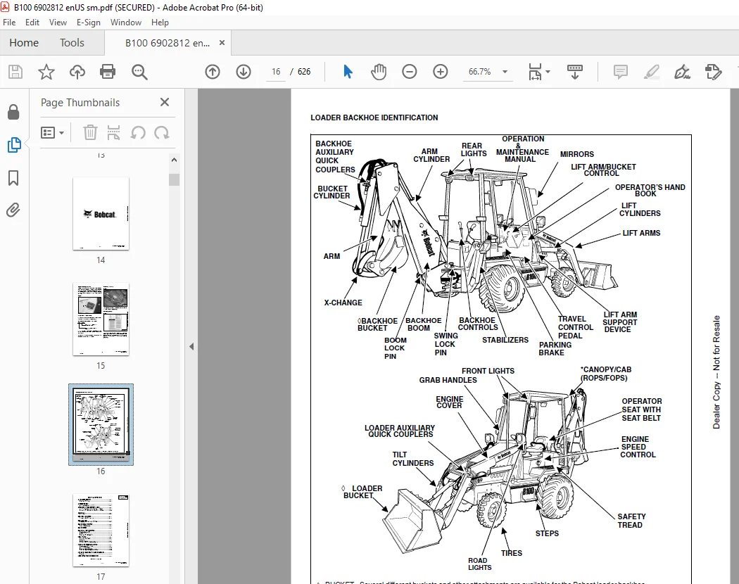
LOADER BACKHOE IDENTIFICATION………………………… 16
SAFETY & MAINTENANCE……………………………………. 17
LIFTING AND BLOCKING THE LOADER BACKHOE……………….. 19
Procedure………………………………………. 19
APPROVED LIFT ARM SUPPORT DEVICE……………………… 21
Installing The Approved Lift Arm Support Device…….. 21
Removing The Approved Lift Arm Support Device………. 22
ENGINE COVER……………………………………….. 23
TRANSPORTING THE LOADER BACKHOE………………………. 25
TOWING THE LOADER BACKHOE……………………………. 27
Procedure………………………………………. 27
AXLE TOE-IN………………………………………… 29
Adjustment……………………………………… 29
SERVICE SCHEDULE……………………………………. 31
Chart………………………………………….. 31
AIR CLEANER SERVICE…………………………………. 33
Replacing The Filter…………………………….. 33
ENGINE COOLING SYSTEM……………………………….. 35
Coolant Replacement……………………………… 35
FUEL SYSTEM………………………………………… 37
Fuel Specifications……………………………… 37
Filling The Fuel Tank……………………………. 37
Fuel Filter…………………………………….. 37
Removing Air From The Fuel System…………………. 39
ENGINE LUBRICATION SYSTEM……………………………. 41
Checking Engine Oil……………………………… 41
Oil Chart………………………………………. 41
Replacing The Oil And Filter……………………… 42
HYDRAULIC/HYDROSTATIC SYSTEM…………………………. 45
Checking And Adding Fluid………………………… 45
Cleaning The Cooler……………………………… 46
Replacing Hydraulic/Hydrostatic Filter…………….. 46
Replacing Hydraulic Fluid………………………… 47
REAR AXLE………………………………………….. 49
Checking Oil Level………………………………. 49
Draining Oil……………………………………. 49
BOOM LOCK PIN………………………………………. 51
Engaging And Disengaging The Pin………………….. 51
SWING LOCK PIN……………………………………… 53
Engaging The Swing Lock Pin………………………. 53
BOB-TACH HAND LEVER…………………………………. 55
Inspection And Maintenance……………………….. 55
ALTERNATOR BELT…………………………………….. 57
Adjusting The Alternator Belt…………………….. 57
LUBRICATING THE LOADER BACKHOE……………………….. 59
TIRE MAINTENANCE……………………………………. 67
Wheel Nuts……………………………………… 67
Mounting……………………………………….. 67
Tire Pressure…………………………………… 67
HYDRAULIC SYSTEM……………………………………….. 69
HYDRAULIC/HYDROSTATIC SCHEMATIC………………………. 73
HYDRAULIC SYSTEM INFORMATION…………………………. 75
Troubleshooting…………………………………. 78
Description…………………………………….. 79
ARM CYLINDER……………………………………….. 81
Checking……………………………………….. 81
Removal And Installation…………………………. 82
Parts Identification…………………………….. 85
Disassembly…………………………………….. 86
Assembly……………………………………….. 88
BOOM CYLINDER………………………………………. 91
Checking……………………………………….. 91
Removal And Installation…………………………. 93
Parts Identification…………………………….. 96
Disassembly…………………………………….. 97
Assembly……………………………………….. 99
SWING CYLINDER………………………………………101
Checking………………………………………..101
Removal And Installation………………………….102
Parts Identification……………………………..105
Disassembly……………………………………..106
Assembly………………………………………..109
Bushing Removal And Installation…………………..111
BUCKET CYLINDER……………………………………..113
Checking………………………………………..113
Removal And Installation………………………….115
Parts Identification……………………………..118
Disassembly……………………………………..119
Assembly………………………………………..121
STABILIZER CYLINDER………………………………….123
Checking………………………………………..123
Removal And Installation………………………….125
Parts Identification……………………………..127
Disassembly……………………………………..128
Assembly………………………………………..132
TILT CYLINDER……………………………………….137
Checking………………………………………..137
Removal And Installation………………………….138
Parts Identification……………………………..139
Disassembly……………………………………..140
Assembly………………………………………..142
LIFT CYLINDER……………………………………….145
Checking………………………………………..145
Removal And Installation………………………….146
Parts Identification……………………………..147
Disassembly……………………………………..148
Assembly………………………………………..150
STEERING CYLINDER……………………………………153
Checking………………………………………..153
Removal And Installation………………………….154
Parts Identification……………………………..157
Disassembly……………………………………..158
Assembly………………………………………..161
MAIN RELIEF VALVE……………………………………167
Testing The Main Relief Valve……………………..167
Adjustment………………………………………168
PORT RELIEF VALVE (BACKHOE CONTROL VALVE)………………169
Testing And Adjusting (Arm Control)………………..169
Testing And Adjusting (Boom Control)……………….171
Testing And Adjusting (Boom Swing Control)………….173
Testing And Adjusting (Bucket Control)……………..175
PORT RELIEF VALVE (LOADER CONTROL VALVE)……………….177
Testing And Adjusting (Bucket Tilt)………………..177
Testing And Adjusting (Front Auxiliary)…………….179
LOADER CONTROL VALVE…………………………………181
Removal And Installation………………………….181
Parts Identification……………………………..183
Disassembly And Assembly………………………….184
Inlet/Outlet Valve Section………………………..185
Lift Arm Valve Section……………………………187
Tilt Valve Section……………………………….190
Auxiliary Valve Section…………………………..194
BACKHOE CONTROL VALVE………………………………..199
Removal And Installation………………………….199
Parts Identification……………………………..201
Disassembly And Assembly………………………….202
Inlet/Outlet Valve Section………………………..204
Arm Valve Section………………………………..206
Bucket Valve Section……………………………..209
Right Stabilizer Valve Section…………………….213
Left Stabilizer Valve Section……………………..216
Boom Valve Section……………………………….220
Boom Swing Valve Section………………………….223
Outlet Valve Section……………………………..226
HYDRAULIC FLUID RESERVOIR…………………………….227
Removal And Installation………………………….227
Strainer Removal And Installation………………….229
HYDRAULIC FILTER HOUSING……………………………..231
Removal And Installation………………………….231
Disassembly……………………………………..232
Assembly………………………………………..233
GEAR PUMP…………………………………………..235
Removal And Installation………………………….235
Parts Identification……………………………..236
Disassembly And Assembly………………………….237
Inspection………………………………………239
STEERING PUMP……………………………………….241
Removal And Installation………………………….241
Parts Identification……………………………..242
Disassembly……………………………………..243
Inspection………………………………………252
Assembly………………………………………..252
TRAVEL PEDAL………………………………………..261
Removal And Installation………………………….261
Parts Identification……………………………..262
Disassembly And Assembly………………………….263
PRESS TO DRIVE VALVE…………………………………269
Removal And Installation………………………….269
Disassembly And Assembly………………………….271
HYDROSTATIC SYSTEM………………………………………275
HYDROSTATIC SYSTEM INFORMATION………………………..277
Troubleshooting Chart…………………………….277
Replenishing Valve Function……………………….278
OIL COOLER………………………………………….279
Removal And Installation………………………….279
Parts Identification……………………………..280
HYDROSTATIC DRIVE MOTOR………………………………281
Removal And Installation………………………….281
Parts Identification……………………………..283
Disassembly……………………………………..284
Inspection………………………………………288
Assembly………………………………………..290
HYDROSTATIC PUMP…………………………………….295
Removal And Installation………………………….295
Parts Identification……………………………..298
Disassembly……………………………………..300
Inspection………………………………………316
Assembly………………………………………..318
HYDROSTATIC TESTING………………………………….335
Pump Adjustment………………………………….335
DRIVE SYSTEM……………………………………………339
PARKING BRAKE……………………………………….341
Lever Removal And Installation…………………….341
Cable Removal And Installation…………………….342
Adjustment………………………………………344
BRAKE CALIPER……………………………………….345
Removal And Installation………………………….345
Parts Identification……………………………..348
Disassembly And Assembly………………………….349
REAR AXLE AND DIFFERENTIAL……………………………355
Removal And Installation………………………….355
AXLE AND DIFFERENTIAL………………………………..359
Troubleshooting Chart…………………………….359
General Information………………………………360
Wheel Hub/Axle Parts Identification………………..360
Wheel Hub/Axle Disassembly………………………..361
Differential Parts Identification………………….364
Differential Disassembly………………………….365
Differential Inspection…………………………..371
Pinion Group Parts Identification………………….372
Pinion Group Disassembly………………………….373
Pinion Group Inspection…………………………..376
Pinion Group Assembly…………………………….377
Differential Assembly…………………………….384
Wheel Hub/Axle Assembly…………………………..393
MAIN FRAME……………………………………………..397
OPERATOR CAB………………………………………..399
Removal And Installation………………………….399
Cab Mount Removal And Installation…………………406
OPERATOR SEAT……………………………………….407
Removal And Installation………………………….407
FLOOR PANELS………………………………………..409
Left Front Panel Removal And Installation…………..409
Right Front Panel Removal And Installation………….409
Rear Panel Removal And Installation………………..410
GRILL………………………………………………411
Removal And Installation………………………….411
GRILL FRAME…………………………………………413
Removal And Installation………………………….413
ENGINE SIDE COVERS…………………………………..415
Removal And Installation………………………….415
FENDER……………………………………………..417
Removal And Installation………………………….417
ENGINE COVER………………………………………..419
Removal And Installation………………………….419
FUEL TANK…………………………………………..421
Removal And Installation………………………….421
Fuel Fill Screen Removal And Installation…………..422
LIFT ARMS…………………………………………..423
Removal And Installation………………………….423
BOB-TACH……………………………………………427
Removal And Installation………………………….427
Bob-Tach Lever And Wedge………………………….428
Pivot Pin Bushing Removal And Installation………….430
FRONT AXLE………………………………………….431
Removal And Installation………………………….431
Pivot Bushing Removal And Installation……………..433
AXLE HUB (FRONT)…………………………………….435
Removal And Installation………………………….435
SPINDLE…………………………………………….439
Removal And Installation………………………….439
ARM………………………………………………..443
Removal And Installation………………………….443
Arm Pivot Bushing Removal And Installation………….445
BOOM……………………………………………….447
Removal And Installation………………………….447
Boom Pivot Bushing Removal And Installation…………448
SWING FRAME…………………………………………449
Removal And Installation………………………….449
Boom Pivot Bushing Removal And Installation…………450
Trunion Bushing Removal And Installation……………451
X-CHANGE……………………………………………453
Removal And Installation………………………….453
BUCKET……………………………………………..455
Backhoe Bucket Teeth Removal And Installation……….455
Loader Bucket Teeth Removal And Installation………..455
STABILIZER………………………………………….457
Removal And Installation………………………….457
ELECTRICAL SYSTEM AND ANALYSIS……………………………459
ELECTRICAL SCHEMATIC…………………………………461
ELECTRICAL SYSTEM INFORMATION…………………………463
Troubleshooting Chart…………………………….463
Description……………………………………..464
Fuse Location……………………………………464
BATTERY…………………………………………….465
Removal And Installation………………………….465
Servicing The Electrical System……………………466
Using A Booster Battery (Jump Starting)…………….467
ALTERNATOR………………………………………….469
Adjusting The Alternator Belt……………………..469
Description……………………………………..469
Tests…………………………………………..470
Alternator Output Test……………………………470
Full Field Test………………………………….471
Alternator Regulator Test…………………………471
Alternator Regulator Test With Voltmeter……………472
Removal And Installation………………………….473
Parts Identification……………………………..474
Pulley Removal And Installation……………………475
Disassembly And Assembly………………………….476
Rotor Continuity Test…………………………….479
Stator Continuity Test……………………………479
Rectifier Continuity (Diode) Test………………….480
Brush Length…………………………………….480
STARTER…………………………………………….481
Removal And Installation………………………….481
Checking The Starter In The Loader…………………481
Parts Identification……………………………..483
Disassembly……………………………………..484
Inspection And Repair…………………………….489
No Load Test…………………………………….493
Assembly………………………………………..494
CAB LIGHTS………………………………………….501
Bulb Removal And Installation……………………..501
Housing Removal And Installation…………………..503
FUEL LEVEL SENDER……………………………………505
Removal And Installation………………………….505
Testing…………………………………………506
INSTRUMENT PANEL…………………………………….507
Removal And Installation………………………….507
ENGINE SERVICE………………………………………….509
TROUBLESHOOTING……………………………………..513
Chart…………………………………………..513
ENGINE SPEED CONTROL…………………………………515
Removal And Installation………………………….515
Cable Removal And Installation…………………….516
MUFFLER…………………………………………….517
Removal And Installation………………………….517
AIR CLEANER…………………………………………519
Housing Removal And Installation…………………..519
RADIATOR……………………………………………521
Removal And Installation………………………….521
ENGINE COMPONENTS AND TESTING…………………………523
Checking Engine Compression……………………….523
Checking Glow Plugs………………………………524
Glow Plug Removal And Installation…………………525
Fuel Shut-Off Solenoid Removal And Installation……..526
Checking Fuel Injection Pump………………………527
Fuel Injection Pump Removal And Installation………..528
Fuel Injection Pump Timing………………………..530
Fuel Injector Nozzles Removal And Installation………531
Checking Fuel Injector, Nozzles……………………533
Thermostat Removal And Installation………………..534
Water Pump Removal And Installation………………..535
ENGINE……………………………………………..537
Removal And Installation………………………….537
Mount Replacement………………………………..542
RECONDITIONING THE ENGINE…………………………….543
Timing Gear Case Cover Removal And Installation……..543
Oil Pump Removal And Installation………………….545
Crankshaft Front Seal Removal And Installation………547
Engine Speed Control Plate Removal And Installation….548
Idle Limit And Fuel Limit Adjustment……………….549
Exhaust Manifold Removal And Installation…………..549
Valve Cover Removal And Installation……………….550
Rocker Arm Removal And Installation………………..551
Push Rod Removal And Installation………………….552
Tappet Removal And Installation……………………553
Water Flange Removal And Installation………………553
Cylinder Head Removal And Installation……………..554
Checking Piston Top Clearance……………………..555
Cylinder Head Disassembly And Assembly……………..556
Servicing The Cylinder Head……………………….557
Combustion Chamber Removal And Installation…………560
Idler Gear Removal And Installation………………..561
Camshaft Removal And Installation………………….562
Fuel Camshaft Removal And Installation……………..564
Oil Pan Removal And Installation…………………..566
Governor Shaft Removal And Installation…………….567
Governor Fork Lever Removal And Installation………..570
Piston Removal And Installation……………………572
Checking The Piston And Connecting Rod……………..572
Connecting Rod Alignment………………………….573
Piston Ring Gap………………………………….573
Piston Ring Installation………………………….574
Connecting Rod Installation……………………….575
Checking Engine Cylinder Bore……………………..575
Crankshaft Removal And Installation………………..576
Checking Crankshaft Journal And Block Bearing……….578
Checking Crankshaft Journal And Main Bearing………..579
Connecting Rod Journal……………………………580
Checking The End Play Of The Crankshaft…………….581
Crankshaft Alignment……………………………..581
Engine Timing Installation………………………..582
Timing Gear Backlash, Idler Gear And Crankshaft……..582
Idler Gear And Camshaft Gear………………………583
Idler Gear And Fuel Camshaft Gear………………….583
Fuel Camshaft Gear And Governor Shaft Gear………….583
FLYWHEEL HOUSING…………………………………….585
Removal And Installation………………………….585
FLYWHEEL……………………………………………587
Removal And Installation………………………….587
Ring Gear Removal And Installation…………………587
RUBBER DRIVE COUPLER…………………………………589
Removal And Installation………………………….589
Disassembly……………………………………..589
TURBOCHARGER………………………………………..591
Checking………………………………………..591
Description……………………………………..591
Removal And Installation………………………….591
FUEL PUMP…………………………………………..595
Removal And Installation………………………….595
SPECIFICATIONS………………………………………….597
LOADER BACKHOE SPECIFICATIONS…………………………599
Dimensions………………………………………599
Backhoe Rated Lift Capacity (Per SAE J31)…………..600
Performance……………………………………..601
Controls………………………………………..601
Engine………………………………………….601
Hydraulic System…………………………………602
Electrical………………………………………603
Drive System…………………………………….603
Capacities………………………………………603
Tires…………………………………………..603
ENGINE SPECIFICATIONS………………………………..605
Engine Compression……………………………….605
Fuel Injection Nozzles……………………………605
Fuel Injection Pump………………………………605
Cylinder Head……………………………………605
Valves………………………………………….605
Valve Springs……………………………………606
Rocker Arms……………………………………..606
Camshaft………………………………………..606
Cylinders……………………………………….606
Piston Rings…………………………………….607
Pistons…………………………………………607
Crankshaft………………………………………607
Oil Pump………………………………………..608
Thermostat………………………………………608
Grinding Specifications for the Crankshaft………….609
LOADER BACKHOE TORQUE………………………………..611
Specifications…………………………………..611
TORQUE SPECIFICATIONS FOR BOLTS……………………….613
Torque For General Metric Bolts……………………613
HYDRAULIC/HYDROSTATIC FLUID SPECIFICATIONS……………..615
Specifications…………………………………..615
CONVERSIONS…………………………………………617
Decimal And Millimeter Equivalents…………………617
U.S. To Metric Conversion…………………………617
SMR……………………………………………………619
B100-1……………………………………………..619
B100-2……………………………………………..621
B100-3……………………………………………..623
B100-4……………………………………………..625
Need help? Contact: [email protected]
https://vimeo.com/841601104?share=copy
DESCRIPTION:
BOBCAT B100 B-Series SN 572111001 Service Manual PDF DOWNLOAD
This manual is for the Bobcat loader mechanic. It provides necessary servicing and adjustment procedures for the Bobcat loader and its component parts and systems. Refer to the Operation & Maintenance Manual for operating instructions, Starting procedure, daily checks, etc.
A general inspection of the following items must be made after the loader has had service or repair:
- Check that ROPS mounting hardware is tightened and is Bobcat approved.
- The seat belt must be correctly installed, functional and in good condition.
- Check lift arm support device, replace if damaged.
- Machine signs must be legible and in the correct location.
- Foot pedal must return to neutral.
- Check for correct function of the work lights.
- The parking brake must function correctly.
- Enclosure door latches must open and close freely.
- Bob-Tach wedges and linkages must function correctly and be in good condition.
- Safety treads must be in good condition.
- Check for correct function of indicator lamps (Optional on some models).
- Check hydraulic fluid level, engine oil level and fuel supply.
- Inspect for fuel, oil or hydraulic fluid leaks.
- Lubricate the loader backhoe.
- Check the condition of the battery and cables.
- Inspect the air cleaner for damage or leaks. Check the condition of the element.
- Check the electrical charging system.
- Check tires for wear and pressure.
- Inspect for loosen or broken parts or connections.
- Operate the loader and check all functions.
- Check for any field modification not completed.
- Recommend to the owner that all necessary corrections be made before the machine is returned to service.
PLEASE NOTE:
- This is the same manual used by the dealers to diagnose and troubleshoot your vehicle
- You will be directed to the download page as soon as the purchase is completed. The whole payment and downloading process will take anywhere between 2-5 minutes
- Need any other service / repair / parts manual, please feel free to contact [email protected] . We still have 50,000 manuals unlisted
G.P