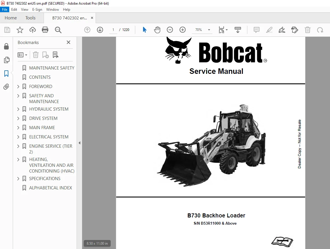
BOBCAT B730 Backhoe Loader Service Manual SN B53R11000 PDF DOWNLOAD
$37.95
BOBCAT B730 Backhoe Loader Service Manual SN B53R11000 PDF DOWNLOAD
Description
BOBCAT B730 Backhoe Loader Service Manual SN B53R11000 PDF DOWNLOAD
FILE DETAILS:
BOBCAT B730 Backhoe Loader Service Manual SN B53R11000 PDF DOWNLOAD
Language : English
Pages : 1220
Downloadable : Yes
File Type : PDF
IMAGES PREVIEW OF THE MANUAL:
TABLE OF CONTENTS:
BOBCAT B730 Backhoe Loader Service Manual SN B53R11000 PDF DOWNLOAD
MAINTENANCE SAFETY…………………………………………….. 3
CONTENTS……………………………………………………… 5
FOREWORD……………………………………………………… 7
FOREWORD………………………………………………….. 9
SAFETY INSTRUCTIONS………………………………………… 11
Before Operation……………………………………….. 11
Safe Operation Is The Operator’s Responsibility……………. 12
Safe Operation Needs A Qualified Operator…………………. 12
Avoid Silica Dust………………………………………. 13
Dismantling And Disposal………………………………… 13
General Safety Information………………………………. 13
Crushing And Burning Prevention………………………….. 14
Fire And Explosion Prevention……………………………. 15
Machine Startup Safety………………………………….. 15
Engine Startup And Operating Safety………………………. 16
Machine Operating Safety………………………………… 16
Machine Parking Safety………………………………….. 18
Machine Transporting Safety……………………………… 18
Machine Towing Safety…………………………………… 18
Machine Maintenance Safety………………………………. 19
During Maintenance……………………………………… 21
Hydraulic Lines And Hoses……………………………….. 21
PUBLICATIONS AND TRAINING RESOURCES………………………….. 23
SERIAL NUMBER LOCATION……………………………………… 24
Backhoe Loader Serial Number…………………………….. 24
Engine Serial Number……………………………………. 24
Other Serial Numbers……………………………………. 24
DELIVERY REPORT……………………………………………. 25
BOBCAT BACKHOE LOADER IDENTIFICATION…………………………. 26
SAFETY AND MAINTENANCE…………………………………………. 27
SERVICE SCHEDULE…………………………………………… 31
Maintenance Intervals…………………………………… 31
Lubrication Chart………………………………………. 33
Inspection Checkbook……………………………………. 34
LIFTING AND BLOCKING THE MACHINE…………………………….. 35
Procedure……………………………………………… 35
TOWING THE MACHINE…………………………………………. 37
Procedure……………………………………………… 37
TRANSPORTING THE BACKHOE LOADER ON A TRAILER………………….. 39
Loading And Unloading…………………………………… 39
STOPPING THE ENGINE AND LEAVING THE MACHINE…………………… 41
STORAGE AND RETURN TO SERVICE……………………………….. 43
Storage……………………………………………….. 43
Return To Service………………………………………. 43
OPERATOR CAB………………………………………………. 45
Description……………………………………………. 45
Cab Doors……………………………………………… 45
Windshield Wipers………………………………………. 46
Side Windows…………………………………………… 46
Rear Windows…………………………………………… 46
EMERGENCY EXIT…………………………………………….. 47
BACKHOE BOOM / SWING LOCK…………………………………… 49
Locking And Unlocking The Backhoe Boom / Swing Lock………… 49
APPROVED LIFT ARM SUPPORT DEVICE…………………………….. 51
Description……………………………………………. 51
Installing The Approved Lift Arm Support Device……………. 51
Removing The Approved Lift Arm Support Device……………… 52
TIRE MAINTENANCE…………………………………………… 53
Wheel Nuts…………………………………………….. 53
Rotating The Tires……………………………………… 53
Wheel Replacement………………………………………. 53
Mounting The Tires……………………………………… 54
Tire Pressure………………………………………….. 54
ENGINE COVER………………………………………………. 55
Opening And Closing…………………………………….. 55
GRILLE……………………………………………………. 57
Removing And Installing…………………………………. 57
ENGINE AIR CLEANER…………………………………………. 59
Description……………………………………………. 59
Cleaning The Outer Air Filter……………………………. 59
Replacing The Air Filters……………………………….. 60
FUEL SYSTEM……………………………………………….. 61
Fuel Specifications…………………………………….. 61
Biodiesel Blend Fuel……………………………………. 61
Filling The Fuel Tank…………………………………… 62
Draining The Fuel Tank………………………………….. 62
Fuel Filters…………………………………………… 63
ENGINE LUBRICATION SYSTEM…………………………………… 65
Engine Oil Chart……………………………………….. 65
Checking And Adding Engine Oil…………………………… 66
Removing And Replacing Oil And Filter…………………….. 67
ENGINE COOLING SYSTEM………………………………………. 69
Cooling System…………………………………………. 69
Cleaning The Cooling System……………………………… 70
Checking And Adding Coolant……………………………… 70
Removing And Replacing Coolant…………………………… 71
HYDRAULIC SYSTEM…………………………………………… 73
Hydraulic / Hydrostatic Fluid Chart………………………. 73
Checking And Adding Hydraulic Fluid………………………. 74
Removing And Replacing The Hydraulic Filters………………. 75
Removing And Replacing The Hydraulic Fluid………………… 77
REAR AXLE…………………………………………………. 79
Axle And Reduction Gears………………………………… 79
Checking And Adding Oil…………………………………. 79
Draining Oil…………………………………………… 79
Check And Adding Reduction Gear Oil………………………. 79
Draining Reduction Gear Oil……………………………… 79
Parking Brake Inspection / Adjustment…………………….. 80
TRANSMISSION………………………………………………. 81
Checking And Adding Oil…………………………………. 81
Removing And Replacing Oil………………………………. 81
Replacing The Filter Element…………………………….. 82
ALTERNATOR AND FAN BELT…………………………………….. 83
Belt Checking………………………………………….. 83
Belt Adjustment………………………………………… 84
Belt Replacement……………………………………….. 84
ATTACHMENT COUPLING SYSTEMS…………………………………. 85
Loader Attachment Coupling Inspection And Maintenance………. 85
Backhoe Attachment Coupling Inspection And Maintenance……… 85
LUBRICATING THE MACHINE…………………………………….. 87
Lubrication Locations…………………………………… 87
HYDRAULIC SYSTEM………………………………………………. 95
HYDRAULIC / HYDROSTATIC SCHEMATICS…………………………… 99
HYDRAULIC SYSTEM INFORMATION………………………………… 103
Glossary Of Hydraulic / Hydrostatic Symbols……………….. 103
HYDRAULIC SYSTEM…………………………………………… 107
Tests And Hydraulic Pressure Test………………………… 107
Test Ports…………………………………………….. 108
Blocks………………………………………………… 110
ON-OFF Solenoid Valve…………………………………… 112
ON-OFF Pressure Reducing Valve…………………………… 113
Steering Priority Valve…………………………………. 114
Steering Pressure Test………………………………….. 115
Pilot Pressure Test…………………………………….. 116
Pilot Pressure Regulation Block………………………….. 117
Priority Valve…………………………………………. 118
RETURN LINE CHECK VALVE…………………………………….. 121
Removal And Installation………………………………… 121
LOADER ARM LIFT CYLINDERS…………………………………… 123
Removal And Installation………………………………… 123
Parts Identification……………………………………. 124
Disassembly……………………………………………. 125
Inspection…………………………………………….. 126
Assembly………………………………………………. 127
LOADER BUCKET (TILT) CYLINDER……………………………….. 131
Removal And Installation………………………………… 131
Parts Identification……………………………………. 132
Disassembly……………………………………………. 133
Inspection…………………………………………….. 134
Assembly………………………………………………. 135
CLAMPSHELL CYLINDER………………………………………… 137
Removal And Installation………………………………… 137
Parts Identification……………………………………. 138
Disassembly……………………………………………. 139
Inspection…………………………………………….. 140
Assembly………………………………………………. 141
BACKHOE BOOM CYLINDER………………………………………. 145
Removal And Installation………………………………… 145
Parts Identification……………………………………. 147
Disassembly……………………………………………. 148
Inspection…………………………………………….. 149
Assembly………………………………………………. 150
BACKHOE ARM CYLINDER……………………………………….. 153
Removal And Installation………………………………… 153
Parts Identification……………………………………. 155
Disassembly……………………………………………. 156
Inspection…………………………………………….. 157
Assembly………………………………………………. 158
BACKHOE BUCKET CYLINDER…………………………………….. 161
Removal And Installation………………………………… 161
Parts Identification……………………………………. 162
Disassembly……………………………………………. 163
Inspection…………………………………………….. 164
Assembly………………………………………………. 165
TELESCOPIC ARM CYLINDER…………………………………….. 167
Removal And Installation………………………………… 167
Parts Identification……………………………………. 168
Disassembly……………………………………………. 170
Inspection…………………………………………….. 171
Assembly………………………………………………. 172
BACKHOE SWING CYLINDERS…………………………………….. 175
Removal And Installation………………………………… 175
Parts Identification……………………………………. 177
Disassembly……………………………………………. 178
Inspection…………………………………………….. 179
Assembly………………………………………………. 180
BACKHOE STABILIZER CYLINDERS………………………………… 183
Removal And Installation………………………………… 183
Parts Identification……………………………………. 186
Disassembly……………………………………………. 187
Inspection…………………………………………….. 188
Assembly………………………………………………. 189
SIDE SHIFT LOCK CYLINDERS…………………………………… 193
Removal And Installation………………………………… 193
HYDRAULIC PUMP…………………………………………….. 195
Description……………………………………………. 195
Removal And Installation………………………………… 196
BACKHOE CONTROL VALVE………………………………………. 197
Port Locations (ISO Pattern)…………………………….. 197
Removal And Installation………………………………… 201
BRAKE PEDAL AND BOOSTER…………………………………….. 203
Removal And Installation………………………………… 203
HYDRAULIC FLUID RESERVOIR…………………………………… 205
Description……………………………………………. 205
Removal And Installation………………………………… 206
Hydraulic Fluid Screen Removal And Installation……………. 208
Hydraulic Filter Removal And Installation…………………. 208
Hydraulic Suction Strainer Removal And Installation………… 209
LOADER CONTROL VALVE……………………………………….. 211
Port Locations (Mechanical Controls)……………………… 211
Port Locations (Pilot Controls)………………………….. 213
Removal And Installation………………………………… 215
Pressure Relief Valves (PRV) Test And Unloading Valve Test….. 216
STEERING COLUMN AND UNIT……………………………………. 219
Removal And Installation………………………………… 219
BACKHOE DISTRIBUTOR BLOCK…………………………………… 221
Removal And Installation………………………………… 221
DRIVE SYSTEM………………………………………………….. 223
TRANSMISSION (MECHANICAL 2-WHEEL DRIVE)………………………. 227
Description……………………………………………. 227
Removal And Installation………………………………… 228
Tightening Torques……………………………………… 231
Plugs And Filters Disassembly……………………………. 235
Plugs And Filters Assembly………………………………. 238
Converter And Oil Pump Disassembly……………………….. 240
Converter And Oil Pump Assembly………………………….. 242
Pipes Disassembly………………………………………. 245
Pipes Assembly…………………………………………. 246
Hydraulic Control Valve Disassembly………………………. 247
Hydraulic Control Valve Assembly…………………………. 255
Transmission Housing Disassembly…………………………. 261
Transmission Housing Assembly……………………………. 269
Shafts A – D Disassembly………………………………… 279
Shafts A – D Assembly…………………………………… 289
Shafts B – C Disassembly………………………………… 299
Shafts B – C Assembly…………………………………… 309
Speed Controls Disassembly………………………………. 319
Speed Controls Assembly…………………………………. 322
Troubleshooting………………………………………… 325
TRANSMISSION (MECHANICAL 4-WHEEL DRIVE)………………………. 329
Description……………………………………………. 329
Removal And Installation………………………………… 330
Tightening Torques……………………………………… 333
Plugs And Filters Disassembly……………………………. 337
Plugs And Filters Assembly………………………………. 341
Converter And Oil Pump Disassembly……………………….. 344
Converter And Oil Pump Assembly………………………….. 346
Pipes Disassembly………………………………………. 349
Pipes Assembly…………………………………………. 350
Hydraulic Control Valve Disassembly………………………. 351
Hydraulic Control Valve Assembly…………………………. 359
4-Wheel Drive Solenoid Valve Disassembly………………….. 365
4-Wheel Drive Solenoid Valve Assembly…………………….. 367
Transmission Housing Disassembly…………………………. 369
Transmission Housing Assembly……………………………. 379
Shafts A – D Disassembly………………………………… 389
Shafts A – D Assembly…………………………………… 399
Shafts B – C Disassembly………………………………… 409
Shafts B – C Assembly…………………………………… 419
Shaft E Disassembly…………………………………….. 429
Shaft E Assembly……………………………………….. 433
Speed Controls Disassembly………………………………. 439
Speed Controls Assembly…………………………………. 442
Troubleshooting………………………………………… 445
TRANSMISSION (AUTOSHIFT 4-WHEEL DRIVE)……………………….. 449
Description……………………………………………. 449
Removal And Installation………………………………… 450
Tightening Torques……………………………………… 453
Filters Disassembly…………………………………….. 461
Filters Assembly……………………………………….. 463
Check Ports……………………………………………. 465
Oil Pump Disassembly……………………………………. 469
Oil Pump Assembly………………………………………. 471
Switches And Sensors Disassembly…………………………. 473
Switches And Sensors Assembly……………………………. 475
Hydraulic Control Valve Disassembly………………………. 477
Hydraulic Control Valve Assembly…………………………. 484
SAHR Brake Solenoid Valve Disassembly…………………….. 490
SAHR Brake Solenoid Valve Assembly……………………….. 492
SAHR Brake Group Disassembly…………………………….. 493
SAHR Brake Group Assembly……………………………….. 499
Manual Parking Brake Disassembly…………………………. 505
Manual Parking Brake Assembly……………………………. 508
Front Half-Housing Disassembly…………………………… 512
Front Half-Housing Assembly……………………………… 518
Rear Cover – Shafts Disassembly………………………….. 525
Rear Cover – Shafts Assembly…………………………….. 529
Gear Pistons Disassembly………………………………… 535
Gear Pistons Assembly…………………………………… 540
Speed Gears Shift Rails Adjustment……………………….. 552
Speed Gears Switches Check………………………………. 571
Shafts A – D Disassembly………………………………… 583
Shafts A – D Assembly…………………………………… 593
Shafts B – C Disassembly………………………………… 605
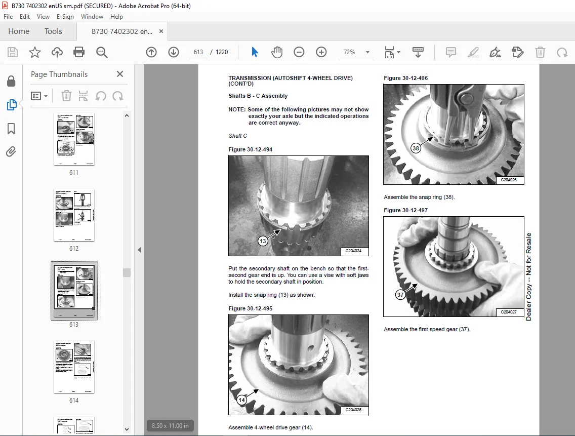
Shafts B – C Assembly…………………………………… 613
4-Wheel Drive Shaft Disassembly………………………….. 624
4-Wheel Drive Shaft Assembly…………………………….. 628
Shift Rails – Forks Disassembly………………………….. 634
Shift Rails – Forks Assembly…………………………….. 636
SAHR Parking Brake……………………………………… 639
4WS Front Half-Housing Disassembly……………………….. 643
4WS Front Half-Housing Assembly………………………….. 649
4-Wheel Drive Shaft – Coaxial TLB1 Disassembly…………….. 658
4-Wheel Drive Shaft – Coaxial TLB1 Assembly……………….. 663
FRONT AXLE (2-WHEEL DRIVE)………………………………….. 673
Description……………………………………………. 673
Removal And Installation………………………………… 674
Tightening Torques……………………………………… 676
Steering Cylinder Group Disassembly………………………. 677
Steering Cylinder Group Assembly…………………………. 678
Wheel Hub Group Disassembly……………………………… 681
Wheel Hub Group Assembly………………………………… 684
Axle Beam Group Disassembly……………………………… 687
Axle Beam Group Assembly………………………………… 689
Toe-In Adjustment………………………………………. 691
Troubleshooting………………………………………… 694
FRONT AXLE (4-WHEEL DRIVE)………………………………….. 695
Description……………………………………………. 695
Removal And Installation………………………………… 697
Tightening Torques……………………………………… 699
Steering Cylinder Group Disassembly………………………. 701
Steering Cylinder Group Assembly…………………………. 703
Epicyclic Reduction Gear Group Disassembly………………… 705
Epicyclic Reduction Gear Group Assembly…………………… 707
Wheel Hub Group Disassembly……………………………… 709
Wheel Hub Group Assembly………………………………… 713
Differential Support Group Disassembly……………………. 717
Differential Support Group Assembly………………………. 720
Bevel Gear Marking Test…………………………………. 725
Differential Group Disassembly…………………………… 726
Differential Group Assembly……………………………… 728
Pinion Group Disassembly………………………………… 729
Pinion Group Assembly…………………………………… 733
Axle Beam Group Disassembly……………………………… 739
Axle Beam Group Assembly………………………………… 741
Toe-In / Steering Angle…………………………………. 743
Toe-In Adjustment………………………………………. 744
Steering Angle Adjustment……………………………….. 746
Wheel And Double U-Joint Group Disassembly………………… 747
Wheel And Double U-Joint Group Assembly…………………… 749
Double U-Joint Seal Ring Replacement On Axle Beam Side……… 751
Double U-Joint Bushing Replacement On Axle Beam Side……….. 752
Testing After Assembly………………………………….. 753
Troubleshooting………………………………………… 754
REAR AXLE…………………………………………………. 759
Description……………………………………………. 759
Removal And Installation………………………………… 761
Tightening Torques……………………………………… 763
Parking Brake Caliper Group Disassembly…………………… 767
Parking Brake Caliper Group Assembly……………………… 769
Epicyclic Reduction Gear Group Disassembly………………… 770
Epicyclic Reduction Gear Group Assembly…………………… 773
Wheel Hub Group Disassembly……………………………… 777
Wheel Hub Group Assembly………………………………… 780
Axle Beam Trumpet Group Disassembly………………………. 782
Axle Beam Trumpet Group Assembly…………………………. 785
Brake Group Disassembly…………………………………. 789
Brake Group Assembly……………………………………. 791
Differential Support Group Disassembly……………………. 793
Differential Support Group Assembly………………………. 796
Differential Group Disassembly…………………………… 802
Differential Group Assembly……………………………… 805
Differential Locking Group Disassembly……………………. 808
Differential Locking Group Assembly………………………. 811
Pinion Group Disassembly………………………………… 814
Pinion Group Assembly…………………………………… 817
Testing After Assembly………………………………….. 823
Troubleshooting………………………………………… 824
FRONT SHAFT……………………………………………….. 829
Removal And Installation………………………………… 829
REAR SHAFT………………………………………………… 831
Removal And Installation………………………………… 831
SERVICE BRAKE……………………………………………… 833
Description……………………………………………. 833
Bleeding The Brake Circuitry…………………………….. 834
Test Procedure…………………………………………. 835
Troubleshooting………………………………………… 836
MAIN FRAME……………………………………………………. 837
BACKHOE BOOM / SWING LOCK…………………………………… 839
Removal And Installation………………………………… 839
BUCKET TEETH………………………………………………. 841
Removal And Installation………………………………… 841
BACKHOE BOOM………………………………………………. 843
Removal And Installation………………………………… 843
CAB (PILOT CONTROL)………………………………………… 845
Removal And Installation………………………………… 845
CAB (MECHANICAL CONTROL)……………………………………. 855
Removal And Installation………………………………… 855
COUNTERWEIGHT……………………………………………… 863
Removal And Installation………………………………… 863
ENGINE COVER………………………………………………. 865
Removal And Installation………………………………… 865
FRONT MUDGUARD…………………………………………….. 867
Removal And Installation………………………………… 867
PARKING LEVER……………………………………………… 869
Removal And Installation………………………………… 869
FUEL TANK…………………………………………………. 871
Removal And Installation………………………………… 871
KINGPOST………………………………………………….. 873
Removal And Installation………………………………… 873
SIDE SHIFT………………………………………………… 875
Removal And Installation………………………………… 875
BACKHOE ARM……………………………………………….. 877
Removal And Installation………………………………… 877
FRONT CONSOLE……………………………………………… 879
Removal And Installation………………………………… 879
STABILIZER WEAR PADS……………………………………….. 883
Adjustment…………………………………………….. 883
ELECTRICAL SYSTEM……………………………………………… 885
ELECTRICAL SCHEMATICS………………………………………. 887
ELECTRICAL SYSTEM………………………………………….. 899
Component Location……………………………………… 899
BATTERY…………………………………………………… 905
Battery Maintenance…………………………………….. 905
Battery Testing………………………………………… 906
Battery Charging……………………………………….. 906
Using A Booster Battery (Jump Starting)…………………… 907
Removing And Installing The Battery………………………. 908
Battery Disconnect Switch……………………………….. 909
FUSES…………………………………………………….. 911
Location………………………………………………. 911
Parts Identification (Synchroshuttle Transmission)…………. 912
Parts Identification (Autoshift Transmission)……………… 913
RELAYS……………………………………………………. 915
Location………………………………………………. 915
Parts Identification (Synchroshuttle Transmission)…………. 916
Parts Identification (Autoshift Transmission)……………… 917
INSTRUMENT PANEL…………………………………………… 919
Removal And Installation………………………………… 919
HORN……………………………………………………… 921
Removal And Installation………………………………… 921
BACK-UP ALARM……………………………………………… 923
Inspection…………………………………………….. 923
Removal And Installation………………………………… 923
TRAVEL DIRECTION CONTROL LEVER………………………………. 925
Removal And Installation………………………………… 925
Parts Identification……………………………………. 926
MULTI-FUNCTION LEVER……………………………………….. 927
Removal And Installation………………………………… 927
FUEL LEVEL SENDER………………………………………….. 929
Removal And Installation………………………………… 929
ENGINE SERVICE (TIER 2)………………………………………… 931
ENGINE INFORMATION…………………………………………. 935
Introduction…………………………………………… 935
Engine Views…………………………………………… 935
Engine Identification…………………………………… 936
Safety Precautions……………………………………… 937
Safety Precautions When The Engine Is Cleaned……………… 938
Engine Lift Equipment…………………………………… 939
Viton Seals……………………………………………. 939
POWERPART Recommended Consumable Products…………………. 940
Troubleshooting………………………………………… 942
ENGINE SPECIFICATIONS………………………………………. 947
Basic Engine Data………………………………………. 947
Data And Dimensions…………………………………….. 948
Thread Sealant…………………………………………. 967
Standard Torque Values………………………………….. 968
Specific Torque Values………………………………….. 969
Compression Test Data…………………………………… 972
CYLINDER HEAD……………………………………………… 973
General Description…………………………………….. 973
Atomiser Cover…………………………………………. 973
Rocker Cover…………………………………………… 974
Rocker Arm…………………………………………….. 976
Valve Tip Clearances……………………………………. 978
Valve Springs………………………………………….. 979
Removal……………………………………………….. 981
Installation…………………………………………… 983
Valve And Valve Springs…………………………………. 986
Valve Guides…………………………………………… 989
Inspection And To Correct……………………………….. 992
PISTON AND CONNECTING ROD ASSEMBLIES…………………………. 995
General Description…………………………………….. 995
Big End Bearing………………………………………… 996
Piston And Connecting Rod……………………………….. 998
Piston Rings……………………………………………1001
Piston And Connecting Rod Assembly………………………..1002
Piston And Piston Rings………………………………….1004
Connecting Rod………………………………………….1005
Partially Finished Small End Bush…………………………1005
Piston Cooling Jets……………………………………..1006
CRANKSHAFT ASSEMBLY…………………………………………1007
General Description……………………………………..1007
Crankshaft Pulley……………………………………….1008
Rear End Oil Seal Assembly……………………………….1009
To Remove And To Fit A Wear Sleeve………………………..1015
Thrust Washers………………………………………….1016
Main Bearings…………………………………………..1020
Crankshaft……………………………………………..1022
Balancer Unit…………………………………………..1026
TIMING CASE AND DRIVE ASSEMBLY……………………………….1031
General Description……………………………………..1031
Timing Cover……………………………………………1032
Mechanical Fuel Pump Gear………………………………..1034
Electronic Fuel Pump Gear………………………………..1038
Idler Gear and Hub………………………………………1040
Heavy Duty Idler Gear……………………………………1043
Camshaft Gear…………………………………………..1045
Front Oil Seal………………………………………….1046
Timing Case…………………………………………….1049
Crankshaft Gear…………………………………………1052
Camshaft And Tappets…………………………………….1053
CYLINDER BLOCK ASSEMBLY……………………………………..1055
General Description……………………………………..1055
Cylinder Block………………………………………….1055
Cylinder Bore…………………………………………..1057
ENGINE TIMING………………………………………………1059
General Description……………………………………..1059
To Set Number 1 Piston To TDC On The Compression Stroke……..1060
To Check The Timing Of The Bosch VP30 Fuel Injection Pump……1062
To Check The Timing Of The Bosch EPVE Fuel Injection Pump……1063
To Adjust The Timing Of The Bosch EPVE Fuel Injection Pump…..1064
To Check The Timing Of The Delphi DP210 Fuel Injection Pump….1065
To Check The Valve Timing………………………………..1066
ASPERATION SYSTEM…………………………………………..1067
General Description……………………………………..1067
Exhaust Elbow…………………………………………..1068
Turbocharger Side Mount………………………………….1069
Turbocharger Faults……………………………………..1072
Open Engine Breather…………………………………….1074
Natural Aspirated Engine Breather…………………………1075
Closed Engine Breather…………………………………..1076
LUBRICATION SYSTEM………………………………………….1077
General Description……………………………………..1077
Lubrication System Flow Diagram…………………………..1078
Canister Type Oil Filter…………………………………1079
Element Type Oil Filter………………………………….1080
Filter Head…………………………………………….1081
Sump…………………………………………………..1082
Dipstick Tube…………………………………………..1084
Oil Strainer And Suction Pipe…………………………….1085
Lubricating Oil Pump Assembly…………………………….1086
Relief Valve……………………………………………1088
FUEL SYSTEM………………………………………………..1091
General Description……………………………………..1091
Cold Start Advance Unit (KSB)…………………………….1093
Typical Fuel System……………………………………..1094
Fuel Filter Assembly…………………………………….1095
Atomizers………………………………………………1096
Fuel Lift Pump And Filter Assembly………………………..1099
Removing Air From The Fuel System…………………………1101
Bosch VP30 Fuel Injection Pump……………………………1102
Bosch EVPE Fuel Injection Pump……………………………1107
Delphi DP210 Fuel Injection Pump………………………….1110
ENGINE COOLING SYSTEM……………………………………….1115
General Description……………………………………..1115
Coolant Flow Diagram…………………………………….1116
Thermostat……………………………………………..1117
Coolant Pump……………………………………………1121
Fan……………………………………………………1126
Fan Drive………………………………………………1126
Lubricating Oil Cooler…………………………………..1127
Coolant Bypass Pipe……………………………………..1129
Oil Cooler / Radiator Removal And Installation……………..1130
Expansion Tank Removal And Installation……………………1131
FLYWHEEL AND HOUSING………………………………………..1133
General Description……………………………………..1133
Flywheel……………………………………………….1133
Ring Gear………………………………………………1133
Flywheel Housing………………………………………..1134
ELECTRICAL SYSTEM…………………………………………..1135
General Description……………………………………..1135
Alternator……………………………………………..1135
Starter Motors………………………………………….1140
Starting Aid (Glow Plug)…………………………………1141
Electrical Components……………………………………1143
Engine Control Module (ECM)………………………………1145
Voltage Load Protection Module……………………………1147
Programming A New ECM……………………………………1148
Speed And Timing Sensor………………………………….1149
Pressure Sensor…………………………………………1150
Temperature Sensor………………………………………1152
Wiring Harness………………………………………….1154
AUXILIARY EQUIPMENT…………………………………………1161
General Description……………………………………..1161
Power Steering Pump……………………………………..1161
Adaptor For A Hydraulic Pump Or A Steering Pump…………….1162
Exhauster………………………………………………1164
SPECIAL TOOLS………………………………………………1165
ENGINE…………………………………………………….1169
Removal And Installation…………………………………1169
ACCELERATOR PEDAL…………………………………………..1175
Removal And Installation…………………………………1175
Cable Removal And Installation……………………………1176
Cable Adjustment………………………………………..1177
EXHAUST……………………………………………………1179
Removal And Installation…………………………………1179
ENGINE AIR CLEANER………………………………………….1181
Removal And Installation…………………………………1181
HEATING, VENTILATION AND AIR CONDITIONING (HVAC)…………………..1183
HVAC UNIT………………………………………………….1185
Removal And Installation…………………………………1185
SPECIFICATIONS…………………………………………………1189
BACKHOE LOADER SPECIFICATIONS………………………………..1191
Machine Dimensions………………………………………1191
Loader Performance………………………………………1193
Backhoe Performance……………………………………..1193
Fork Performance………………………………………..1193
Controls……………………………………………….1193
Brakes…………………………………………………1193
Engine…………………………………………………1194
Hydraulic System………………………………………..1194
Electrical System……………………………………….1194
Drive System……………………………………………1194
Steering……………………………………………….1194
Axles………………………………………………….1195
Tyres………………………………………………….1195
Operating Weight………………………………………..1195
Capacities……………………………………………..1195
Cab……………………………………………………1195
Instrument Panel………………………………………..1196
Temperature Range……………………………………….1196
MACHINE TORQUE SPECIFICATIONS………………………………..1197
Drive Line……………………………………………..1197
Cab……………………………………………………1197
Wheels…………………………………………………1197
TORQUE SPECIFICATIONS FOR BOLTS………………………………1199
Torque For General SAE Bolts……………………………..1199
Torque For General Metric Bolts…………………………..1200
HYDRAULIC CONNECTION SPECIFICATIONS…………………………..1201
O-ring Face Seal Connection………………………………1201
Straight Thread O-ring Fitting……………………………1201
Tubelines And Hoses……………………………………..1201
Flare Fitting…………………………………………..1202
O-ring Flare Fitting…………………………………….1203
Port Seal Fitting……………………………………….1205
REGULAR MAINTENANCE ITEMS……………………………………1207
Parts………………………………………………….1207
Fluids, Lubricants And Fuel………………………………1208
CONVERSIONS………………………………………………..1211
Decimal And Millimeter Equivalent Chart……………………1211
U.S. To Metric Conversion Chart…………………………..1211
SERVICE TOOLS REQUIRED………………………………………1213
Mechanical Tools………………………………………..1213
Hydraulic Tools…………………………………………1216
Electrical Tools………………………………………..1216
ALPHABETICAL INDEX……………………………………………..1217
Customer Support: [email protected]
https://vimeo.com/842083541?share=copy
DESCRIPTION:
BOBCAT B730 Backhoe Loader Service Manual SN B53R11000 PDF DOWNLOAD
This manual is for the Bobcat loader mechanic. It provides necessary servicing and adjustment procedures for the Bobcat loader and its component parts and systems. Refer to the Operation & Maintenance Manual for operating instructions, starting procedure, daily checks, etc.
A general inspection of the following items must be made after the loader has had service or repair:
- Check that ROPS mounting hardware is tightened and is Bobcat approved.
- The seat belt must be correctly installed, functional and in good condition.
- Check lift arm support device, replace if damaged.
- Machine signs must be legible and in the correct location.
- Foot pedal must return to neutral.
- Check for correct function of the work lights.
- The parking brake must function correctly.
- Enclosure door latches must open and close freely.
- Bob-Tach wedges and linkages must function correctly and be in good condition.
- Safety treads must be in good condition.
- Check for correct function of indicator lamps (Optional on some models).
- Check hydraulic fluid level, engine oil level, and fuel supply.
- Inspect for fuel, oil, or hydraulic fluid leaks.
- Lubricate the loader backhoe.
- Check the condition of the battery and cables.
- Inspect the air cleaner for damage or leaks. Check the condition of the element.
- Check the electrical charging system.
- Check tires for wear and pressure.
- Inspect for loosen or broken parts or connections.
- Operate the loader and check all functions.
- Check for any field modification not completed.
- Recommend to the owner that all necessary corrections be made before the machine is returned to service.
PLEASE NOTE:
- This is the same manual used by the dealers to diagnose and troubleshoot your vehicle
- You will be directed to the download page as soon as the purchase is completed. The whole payment and downloading process will take anywhere between 2-5 minutes
- Need any other service / repair / parts manual, please feel free to contact [email protected] . We still have 50,000 manuals unlisted
G.P


