BOBCAT BL-370 B Series Ingersoll Rand Service Manual SN 573211001 PDF DOWNLOAD
$30.95
BOBCAT BL-370 B Series Ingersoll Rand Service Manual SN 573211001 PDF DOWNLOAD
Description
BOBCAT BL-370 B Series Ingersoll Rand Service Manual SN 573211001 PDF DOWNLOAD
FILE DETAILS:
BOBCAT BL-370 B Series Ingersoll Rand Service Manual SN 573211001 PDF DOWNLOAD
Language : English
Pages : 636
Downloadable : Yes
File Type : PDF
IMAGES PREVIEW OF THE MANUAL:
TABLE OF CONTENTS:
BOBCAT BL-370 B Series Ingersoll Rand Service Manual SN 573211001 PDF DOWNLOAD
ALPHABETICAL INDEX…………………………………….. 3
MAINTENANCE SAFETY…………………………………….. 5
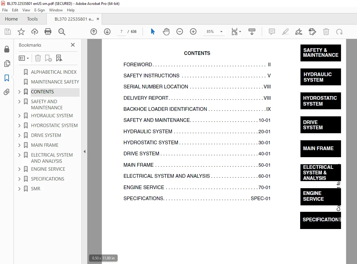
CONTENTS……………………………………………… 7
FOREWORD………………………………………….. 8
SAFETY INSTRUCTIONS………………………………… 11
Before Operation……………………………….. 11
Safe Operation Is The Operator’s Responsibility……. 0
Safe Operation Needs A Qualified Operator…………. 0
Fire Prevention………………………………… 13
SERIAL NUMBER LOCATION……………………………… 14
Backhoe Loader Serial Number…………………….. 14
Engine Serial Number……………………………. 14
DELIVERY REPORT……………………………………. 14
BACKHOE LOADER IDENTIFICATION……………………….. 15
SAFETY AND MAINTENANCE…………………………………. 17
LIFTING AND BLOCKING THE BACKHOE LOADER………………. 19
Procedure……………………………………… 19
APPROVED LIFT ARM SUPPORT DEVICE…………………….. 21
Installing The Approved Lift Arm Support Device……. 21
Removing The Approved Lift Arm Support Device……… 22
ENGINE COVER………………………………………. 23
TRANSPORTING THE BACKHOE LOADER……………………… 25
Procedure……………………………………… 25
TOWING THE BACKHOE LOADER…………………………… 27
Procedure……………………………………… 27
AXLE TOE-IN……………………………………….. 29
Procedure……………………………………… 29
SERVICE SCHEDULE…………………………………… 31
Chart…………………………………………. 31
AIR CLEANER SERVICE………………………………… 33
Replacing The Filter……………………………. 33
ENGINE COOLING SYSTEM………………………………. 35
Cleaning The Cooling System……………………… 35
Checking Coolant Level………………………….. 35
Coolant Replacement…………………………….. 35
FUEL SYSTEM……………………………………….. 37
Fuel Specifications…………………………….. 37
Filling The Fuel Tank…………………………… 37
Fuel Filter……………………………………. 37
Removing Air From The Fuel System………………… 39
ENGINE LUBRICATION SYSTEM…………………………… 41
Checking Engine Oil…………………………….. 41
Oil Chart……………………………………… 41
Replacing The Oil And Filter…………………….. 42
HYDRAULIC/HYDROSTATIC SYSTEM………………………… 45
Checking And Adding Fluid……………………….. 45
Cleaning The Oil Cooler/Radiator…………………. 46
Replacing Hydraulic/Hydrostatic Filter……………. 46
Replacing Hydraulic Fluid……………………….. 47
AXLES (FRONT AND REAR)……………………………… 49
Checking Oil Level (Planetary Carrier)……………. 49
Draining Oil (Planetary Carrier)…………………. 49
Checking Oil Level (Rear Axle)…………………… 50
Draining Oil (Rear Axle)………………………… 50
Checking Oil Level (Front Axle)………………….. 50
Draining Oil (Front Axle)……………………….. 50
BOOM LOCK PIN……………………………………… 51
Engaging And Disengaging The Pin…………………. 51
BOB-TACH HAND LEVER………………………………… 53
Inspection And Maintenance………………………. 53
ALTERNATOR BELT……………………………………. 55
Adjusting The Alternator Belt……………………. 55
LUBRICATING THE BACKHOE LOADER………………………. 57
TIRE MAINTENANCE…………………………………… 65
Wheel Nuts…………………………………….. 65
Mounting………………………………………. 65
Tire Pressure………………………………….. 65
HYDRAULIC SYSTEM………………………………………. 67
HYDRAULIC/HYDROSTATIC SCHEMATICS…………………….. 71
HYDRAULIC SYSTEM INFORMATION………………………… 73
Troubleshooting………………………………… 76
Description……………………………………. 77
ARM CYLINDER………………………………………. 79
Checking………………………………………. 79
Removal And Installation………………………… 80
Parts Identification……………………………. 83
Disassembly……………………………………. 84
Assembly………………………………………. 86
BOOM CYLINDER……………………………………… 89
Checking………………………………………. 89
Removal And Installation………………………… 91
Parts Identification……………………………. 94
Disassembly……………………………………. 95
Assembly………………………………………. 97
SWING CYLINDER……………………………………..101
Checking……………………………………….101
Removal And Installation…………………………102
Parts Identification…………………………….104
Disassembly…………………………………….105
Assembly……………………………………….107
Bushing Removal And Installation………………….110
BUCKET CYLINDER…………………………………….111
Checking……………………………………….111
Removal And Installation…………………………113
Parts Identification…………………………….116
Disassembly…………………………………….117
Assembly……………………………………….119
STABILIZER CYLINDER…………………………………121
Checking……………………………………….121
Removal And Installation…………………………123
Parts Identification…………………………….125
Disassembly…………………………………….126
Assembly……………………………………….130
TILT CYLINDER………………………………………135
Checking……………………………………….135
Removal And Installation…………………………136
Parts Identification…………………………….138
Disassembly…………………………………….139
Assembly……………………………………….141
LIFT CYLINDER………………………………………143
Checking……………………………………….143
Removal And Installation…………………………144
Parts Identification…………………………….146
Disassembly…………………………………….147
Assembly……………………………………….149
STEERING CYLINDER (FRONT)……………………………153
Removal And Installation…………………………153
Parts Identification…………………………….157
Disassembly And Assembly…………………………158
Inspection……………………………………..161
STEERING CYLINDER (REAR)…………………………….163
Removal And Installation…………………………163
Parts Identification…………………………….166
Disassembly And Assembly…………………………167
Inspection……………………………………..170
MAIN RELIEF VALVE…………………………………..171
Description…………………………………….171
Testing………………………………………..171
Adjustment……………………………………..172
PORT RELIEF VALVE (BACKHOE CONTROL VALVE)……………..173
Testing And Adjusting (Arm Control)……………….173
Testing And Adjusting (Bucket Control)…………….174
Testing And Adjusting (Boom Control)………………176
Testing And Adjusting (Boom Swing Control)…………177
PORT RELIEF VALVE (LOADER CONTROL VALVE)………………179
Testing And Adjusting (Bucket Tilt)……………….179
Testing And Adjusting (Front Auxiliary)……………181
LOADER CONTROL VALVE………………………………..183
Removal And Installation…………………………183
Parts Identification…………………………….185
Disassembly And Assembly…………………………186
Inlet/Outlet Valve Section……………………….186
Lift Arm Valve Section…………………………..188
Tilt Valve Section………………………………192
Auxiliary Valve Section (Front)…………………..197
BACKHOE CONTROL VALVE……………………………….203
Removal And Installation…………………………203
Parts Identification…………………………….205
Disassembly And Assembly…………………………206
Inlet/Outlet Valve Section……………………….207
Arm Valve Section……………………………….209
Bucket Valve Section…………………………….212
Right Stabilizer Valve Section……………………216
Left Stabilizer Valve Section…………………….219
Boom Valve Section………………………………223
Boom Swing Valve Section…………………………226
Outlet Valve Section…………………………….229
HYDRAULIC FLUID RESERVOIR……………………………231
Removal And Installation…………………………231
Strainer Removal And Installation…………………233
HYDRAULIC FILTER HOUSING…………………………….235
Removal And Installation…………………………235
Disassembly…………………………………….236
Assembly……………………………………….237
HYDRAULIC FILTER……………………………………239
Removal And Installation…………………………239
GEAR PUMP………………………………………….241
Removal And Installation…………………………241
Parts Identification…………………………….242
Disassembly And Assembly…………………………243
Inspection……………………………………..246
STEERING PUMP………………………………………247
Removal And Installation…………………………247
Parts Identification…………………………….249
Disassembly…………………………………….250
Inspection……………………………………..259
Assembly……………………………………….259
STEERING VALVE……………………………………..269
Removal And Installation…………………………269
Wheel Alignment Procedure………………………..269
MASTER CYLINDER…………………………………….271
Removal And Installation…………………………271
Parts Identification…………………………….272
Disassembly And Assembly…………………………273
HYDROSTATIC SYSTEM……………………………………..275
HYDROSTATIC SYSTEM INFORMATION……………………….277
Troubleshooting Chart……………………………277
Replenishing Valve Function………………………278
OIL COOLER/RADIATOR…………………………………279
Description…………………………………….279
HYDROSTATIC DRIVE MOTOR……………………………..281
Removal And Installation…………………………281
Parts Identification…………………………….283
Disassembly…………………………………….284
Inspection……………………………………..299
Assembly……………………………………….302
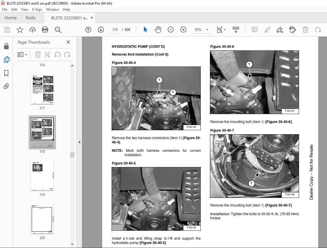
HYDROSTATIC PUMP……………………………………317
Removal And Installation…………………………317
Parts Identification…………………………….320
Disassembly…………………………………….321
Inspection……………………………………..336
Assembly……………………………………….339
HYDROSTATIC PUMP TESTING…………………………….355
Hydrostatic Pump Work Sheet………………………355
Pump Testing……………………………………358
DRIVE SYSTEM…………………………………………..363
TROUBLESHOOTING…………………………………….365
Chart………………………………………….365
PARKING BRAKE HOUSING……………………………….367
Removal And Installation…………………………367
Parts Identification…………………………….368
Disassembly And Assembly…………………………369
SERVICE BRAKE………………………………………379
Description…………………………………….379
Bleeding The Brake Circuit……………………….379
REAR AXLE………………………………………….381
Removal………………………………………..381
Installation……………………………………384
FRONT AXLE…………………………………………389
Removal………………………………………..389
Installation……………………………………391
Axle Pivot Bushing Removal And Installation………..392
Axle Pivot Bushing Removal And Installation………..393
DRIVESHAFT…………………………………………395
Removal And Installation…………………………395
DROP BOX…………………………………………..397
Removal And Installation…………………………397
Parts Identification…………………………….400
Disassembly…………………………………….402
Inspection……………………………………..407
Assembly……………………………………….409
BRAKE PEDAL ASSEMBLY………………………………..417
Removal And Installation…………………………417
MAIN FRAME…………………………………………….421
OPERATOR CANOPY…………………………………….423
Removal And Installation…………………………423
ENCLOSED CAB……………………………………….429
Not Available At Time Of Print……………………429
OPERATOR SEAT………………………………………431
Removal And Installation…………………………431
FLOOR PANELS……………………………………….433
Front Panel Removal And Installation………………433
Rear Panel Removal And Installation……………….433
Front Right Panel Removal And Installation…………434
Front Left Panel Removal And Installation………….434
GRILL……………………………………………..435
Removal And Installation…………………………435
GRILL FRAME………………………………………..437
Removal And Installation…………………………437
ENGINE SIDE COVERS………………………………….439
Removal And Installation…………………………439
FENDER…………………………………………….441
Removal And Installation…………………………441
ENGINE COVER……………………………………….443
Removal And Installation…………………………443
FUEL TANK………………………………………….445
Removal And Installation…………………………445
Screen Removal And Installation…………………..447
LIFT ARMS………………………………………….449
Removal And Installation…………………………449
BOB-TACH…………………………………………..455
Removal And Installation…………………………455
Bob-Tach Lever And Wedge…………………………456
Pivot Pin Bushing Removal And Installation…………458
ARM……………………………………………….459
Removal And Installation…………………………459
Arm Pivot Bushing Removal And Installation…………461
BOOM………………………………………………463
Removal And Installation…………………………463
Boom Pivot Bushing Removal And Installation………..464
SWING FRAME………………………………………..465
Removal And Installation…………………………465
X-CHANGE™………………………………………….467
Removal And Installation…………………………467
BUCKET…………………………………………….469
Backhoe Bucket Teeth Removal And Installation………469
Loader Bucket Teeth Removal And Installation……….469
LIFT ARM STABILIZER…………………………………471
Removal And Installation…………………………471
CENTER FLOOR PANEL………………………………….473
Removal And Installation…………………………473
STABILIZER…………………………………………477
Removal And Installation…………………………477
ELECTRICAL SYSTEM AND ANALYSIS…………………………..479
ELECTRICAL SCHEMATICS……………………………….481
ELECTRICAL SYSTEM INFORMATION………………………..483
Troubleshooting Chart……………………………483
Description…………………………………….484
Fuse And Relay Location………………………….484
Relay Location………………………………….484
BATTERY……………………………………………485
Removal And Installation…………………………485
Servicing The Electrical System…………………..486
Using A Booster Battery (Jump Starting)……………487
ALTERNATOR…………………………………………489
Adjusting The Alternator Belt…………………….489
Description…………………………………….489
Tests………………………………………….490
Alternator Output Test…………………………..490
Full Field Test…………………………………491
Alternator Regulator Test………………………..491
Alternator Regulator Test With Voltmeter…………..492
Alternator Removal And Installation……………….493
Parts Identification…………………………….494
Pulley Removal And Installation…………………..495
Disassembly And Assembly…………………………496
Rotor Continuity Test……………………………499
Stator Continuity Test…………………………..499
Rectifier Continuity (Diode) Test…………………500
Brush Length……………………………………500
STARTER……………………………………………501
Removal And Installation…………………………501
Checking The Starter In The Loader………………..501
Parts Identification…………………………….503
Disassembly…………………………………….504
Inspection And Repair……………………………509
No Load Test……………………………………513
Assembly……………………………………….514
FRONT LIGHTS……………………………………….521
Bulb Removal And Installation…………………….521
Housing Removal And Installation………………….523
TURN INDICATOR LIGHTS (FRONT)………………………..525
Bulb Removal And Installation…………………….525
TURN INDICATOR LIGHTS (REAR)…………………………527
Bulb Removal And Installation…………………….527
FUEL LEVEL SENDER…………………………………..529
Removal And Installation…………………………529
INSTRUMENT PANEL……………………………………531
Removal And Installation…………………………531
ENGINE SERVICE…………………………………………533
TROUBLESHOOTING…………………………………….535
Chart………………………………………….535
ENGINE SPEED CONTROL………………………………..537
Removal And Installation…………………………537
Cable And Rod Removal And Installation…………….538
TRAVEL PEDAL……………………………………….541
Removal And Installation…………………………541
MUFFLER……………………………………………545
Removal And Installation…………………………545
AIR CLEANER………………………………………..547
Removal And Installation…………………………547
OIL COOLER/RADIATOR…………………………………549
Removal And Installation…………………………549
Disassembly…………………………………….551
Inspection……………………………………..552
Assembly……………………………………….552
ENGINE COMPONENTS AND TESTING………………………..555
Engine Compression Checking………………………555
Glow Plugs Removal And Installation……………….556
Checking The Glow Plug…………………………..557
Fuel Shut-off Solenoid Removal And Installation…….558
Fuel Injection Pump Check………………………..559
Fuel Injection Pump Removal And Installation……….560
Fuel Injection Pump Timing……………………….563
Fuel Injector Nozzles Removal And Installation……..565
Fuel Injector Nozzle Check……………………….567
Valve Clearance Adjustment……………………….568
ENGINE…………………………………………….569
Removal And Installation…………………………569
Mount Replacement……………………………….573
RECONDITIONING THE ENGINE……………………………575
Cylinder Head Removal And Installation…………….575
Cylinder Head Disassembly And Assembly…………….578
Cylinder Head Servicing………………………….579
Cylinder Head Top Clearance………………………579
Valve Guide Checking…………………………….580
Reconditioning The Valve And Valve Seat……………582
Valve Spring……………………………………583
Rocker Arm And Shaft Checking…………………….584
Timing Gearcase Cover Removal And Installation……..584
Idler Gear And Camshaft Removal And Installation……587
Camshaft Servicing………………………………588
Idler Gear And Shaft Servicing……………………589
Timing Gears Checking Backlash……………………590
Fuel Camshaft Removal And Installation…………….590
Fuel Camshaft Governor…………………………..591
Crankshaft Gear Removal And Installation…………..591
Oil Pump Removal And Installation…………………592
Oil Pump Service………………………………..592
Checking Engine Oil Pressure……………………..593
Valve Tappets…………………………………..594
Piston And Connecting Rod Removal And Installation….594
Piston And Connecting Rod Servicing……………….596
Connecting Rod Alignment…………………………598
Crankshaft And Bearings Removal And Installation……599
Crankshaft And Bearings Servicing…………………601
Cylinder Bore Checking…………………………..604
Water Pump Removal And Installation……………….604
Water Pump Disassembly And Assembly……………….605
Fan Removal And Installation……………………..606
FLYWHEEL HOUSING……………………………………607
Removal And Installation…………………………607
FLYWHEEL…………………………………………..609
Removal And Installation…………………………609
Ring Gear Removal And Installation………………..609
DRIVE COUPLER………………………………………611
Removal And Installation…………………………611
TURBO……………………………………………..613
Not Available At Time Of Print……………………613
SPECIFICATIONS…………………………………………615
LOADER SPECIFICATIONS……………………………….617
Backhoe Loader Dimensions………………………..617
Loader Performance………………………………618
Backhoe Performance……………………………..618
Controls……………………………………….618
Engine…………………………………………618
Hydraulic System………………………………..619
Drive System……………………………………619
Electrical……………………………………..620
Tires………………………………………….620
Capacities……………………………………..620
ENGINE SPECIFICATIONS……………………………….621
Fuel Injection Nozzles…………………………..621
Fuel Injection Pump……………………………..621
Cylinder Head…………………………………..621
Valves…………………………………………621
Valve Springs…………………………………..622
Valve Timing……………………………………622
Rocker Arms…………………………………….622
Camshaft……………………………………….622
Cylinders………………………………………622
Tappet…………………………………………622
Piston Rings……………………………………623
Pistons………………………………………..623
Crankshaft……………………………………..623
Oil Pump……………………………………….623
Thermostat……………………………………..624
Connecting Rods…………………………………624
Timing Gear…………………………………….624
Cylinder Liner………………………………….624
Engine Bolt Torque………………………………625
Grinding Specifications for the Crankshaft…………626
BACKHOE LOADER TORQUE……………………………….627
Specifications………………………………….627
TORQUE SPECIFICATIONS FOR BOLTS………………………629
Torque For General Metric Bolts…………………..629
HYDRAULIC/HYDROSTATIC FLUID SPECIFICATIONS…………….631
Specifications………………………………….631
CONVERSIONS………………………………………..633
Decimal And Millimeter Equivalents………………..633
U.S. To Metric Conversion………………………..633
SMR ………………………………………………….635
BL-370-1…………………………………………..635
Contact us: [email protected]
DESCRIPTION:
BOBCAT BL-370 B Series Ingersoll Rand Service Manual SN 573211001 PDF DOWNLOAD
FOREWORD
This manual is for the Ingersoll-Rand loader mechanic. It provides necessary servicing and
adjustment procedures for the Ingersoll-Rand loader and its component parts and systems. Refer to
the Operation & Maintenance Manual for operating instructions, Starting procedure, daily checks, etc
SAFETY INSTRUCTIONS
Before Operation
Carefully follow the operating and maintenance instructions in this manual.
- The Bobcat Backhoe Loader is highly maneuverable and compact. It is rugged and useful under a wide variety of conditions. This presents an operator with hazards associated with off highway, rough terrain applications, common with Bobcat Backhoe Loader usage.
- The Bobcat Backhoe Loader has an internal combustion engine with resultant heat and exhaust. All exhaust gases can kill or cause illness, so use the Backhoe Loader with adequate ventilation.
- The dealer explains the capabilities and restrictions of the Bobcat Backhoe Loader and attachments for each application. The dealer demonstrates the safe operation according to Bobcat instructional materials, which are also available to operators. The dealer can also identify unsafe modifications or use of unapproved attachments.
- The attachments and buckets are designed for a Rated Operating Capacity (some have restricted lift heights) or Rated Lift Capacity. They are designed for secure fastening to the Bobcat Backhoe Loader. The user must check with the dealer or Bobcat literature to determine safe loads of materials of specified densities for the machine-attachment combination.
The following publications and training materials provide information on the safe use and maintenance of the Bobcat machine and attachments:
PLEASE NOTE:
- This is the same manual used by the dealers to diagnose and troubleshoot your vehicle
- You will be directed to the download page as soon as the purchase is completed. The whole payment and downloading process will take anywhere between 2-5 minutes
- Need any other service / repair / parts manual, please feel free to contact [email protected] . We still have 50,000 manuals unlisted
G.P