Bobcat Compact Excavator E32 Service Manual 6987272 (06-20) – PDF DOWNLOAD
$35.96
Bobcat Compact Excavator E32 Service Manual 6987272 (06-20) – PDF DOWNLOAD
S/N A94H11001 & Above
S/N AC2N11001 & Above
S/N B3CS11001 & Above
S/N B3K911001 & Above
Description
Bobcat Compact Excavator E322 Service Manual 6987272 (06-20) – PDF DOWNLOAD
FILE DETAILS:
Bobcat Compact Excavator E32 Service Manual 6987272 (06-20) – PDF DOWNLOAD
Language : English
Pages :1009
Downloadable : Yes
File Type : PDF
DESCRIPTION:
Bobcat Compact Excavator E32 Service Manual 6987272 (06-20) – PDF DOWNLOAD
S/N A94H11001 & Above
S/N AC2N11001 & Above
S/N B3CS11001 & Above
S/N B3K911001 & Above
FOREWORD
This manual is for the Bobcat excavator mechanic. It provides necessary servicing and adjustment procedures for the Bobcat excavator and its component parts and systems. Refer to the Operation & Maintenance Manual for operating instructions, starting procedure, daily checks, etc.
SAFETY INSTRUCTIONS
Instructions are necessary before operating or servicing machine. Read and understand the Operation & Maintenance Manual, Operator’s Handbook and signs (decals) on machine. Follow warnings and instructions in the manuals when making repairs, adjustments or servicing. Check for correct function after adjustments, repairs or service. Untrained operators and failure to follow instructions can cause injury or death.
The following publications provide information on the safe use and maintenance of the Bobcat machine and attachments:
- The Delivery Report is used to assure that complete instructions have been given to the new owner and that the machine is in safe operating condition.
- The Operation & Maintenance Manual delivered with the machine or attachment contains operating information as well as routine maintenance and service procedures. It is a part of the machine and can be stored in a container provided on the machine. Replacement Operation & Maintenance Manuals can be ordered from your Bobcat dealer.
- Machine signs (decals) instruct on the safe operation and care of your Bobcat machine or attachment. The signs and their locations are shown in the Operation & Maintenance Manual. Replacement signs are available from your Bobcat dealer.
- An Operator’s Handbook fastened to the operator cab. It’s brief instructions are convenient to the operator. The handbook is available from your dealer in an English edition or one of many other languages. See your Bobcat dealer for more information on translated versions.
- The AEM Safety Manual delivered with the machine gives general safety information.
- The Service Manual and Parts Manual are available from your dealer for use by mechanics to do shoptype service and repair work.
IMAGES PREVIEW OF THE MANUAL:
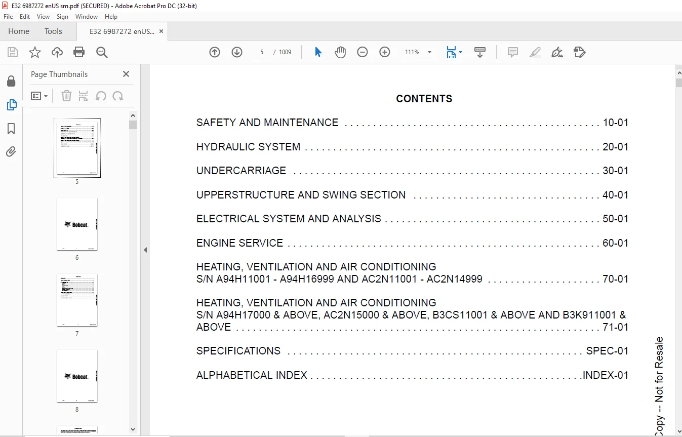
TABLE OF CONTENTS:
Bobcat Compact Excavator E322 Service Manual 6987272 (06-20) – PDF DOWNLOAD
MAINTENANCE SAFETY 3
CONTENTS 5
FOREWORD 7
FOREWORD 9
SAFETY INSTRUCTIONS 11
FIRE PREVENTION 13
Maintenance 13
Operation 13
Electrical 13
Hydraulic System 13
Fueling 13
Starting 13
Spark Arrester Exhaust System 13
Welding And Grinding 14
Fire Extinguishers 14
SERIAL NUMBER LOCATIONS 15
Excavator Serial Number 15
Engine Serial Number 15
DELIVERY REPORT 16
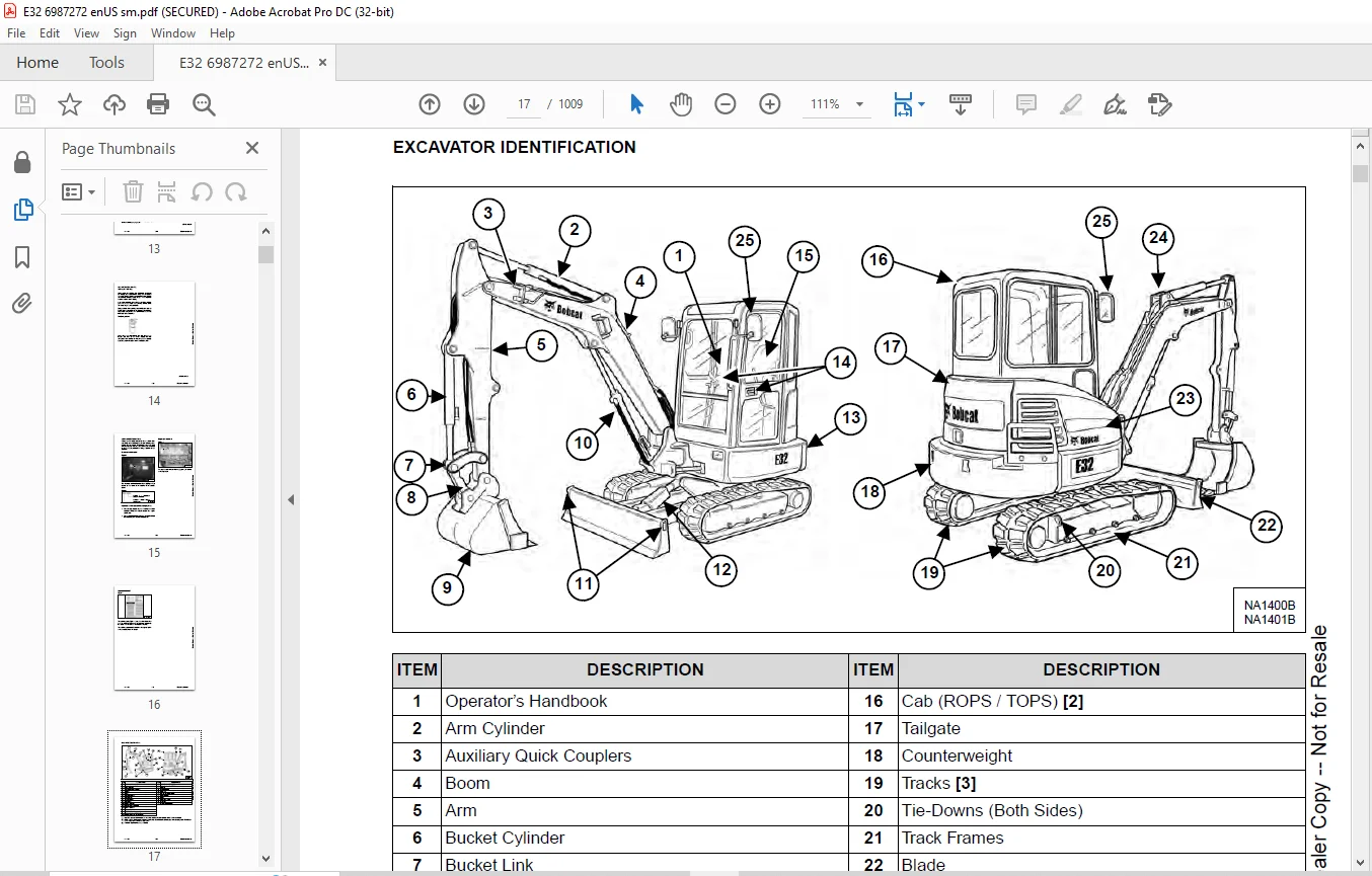
EXCAVATOR IDENTIFICATION 17
SAFETY AND MAINTENANCE 19
LIFTING AND BLOCKING THE EXCAVATOR 23
Procedure 23
LIFTING THE EXCAVATOR 25
Procedure 25
OPERATOR CAB (ROPS / TOPS) 27
Description 27
Cab Door 28
Front Window 29
Front Wiper 30
Window Washer Reservoir 30
Right Side Window 31
OPERATOR CANOPY (ROPS / TOPS) 33
Description 33
TRANSPORTING THE EXCAVATOR ON A TRAILER 35
Loading And Unloading 35
Fastening 36
TAILGATE 37
Opening And Closing 37
Adjusting The Latch 37
RIGHT SIDE COVER 39
Opening And Closing 39
SERVICE SCHEDULE 41
Maintenance Intervals 41
AIR CLEANER SERVICE 43
Daily Check 43
Replacing The Filters 43
CAB FILTERS (S/N A94H11001 – A94H16999 AND AC2N11001 – AC2N14999) 45
Cleaning And Maintenance 45
CAB FILTERS (S/N A94H17000 & ABOVE, AC2N15000 & ABOVE, B3CS11001 & ABOVE AND B3K911001 & ABOVE) 47
Recirculation Filter 47
Fresh Air Filter 47
ENGINE COOLING SYSTEM 49
Cleaning 49
Checking Level 50
Removing And Replacing Coolant 51
FUEL SYSTEM 53
Fuel Specifications 53
Biodiesel Blend Fuel 53
Filling The Fuel Tank 54
Fuel Filters 55
Draining The Fuel Tank 55
Removing Air From The Fuel System 56
ENGINE LUBRICATION SYSTEM 57
Checking And Adding Engine Oil 57
Engine Oil Chart 57
Removing And Replacing Oil And Filter 58
HYDRAULIC SYSTEM 59
Checking And Adding Hydraulic Fluid 59
Hydraulic / Hydrostatic Fluid Chart 60
Removing And Replacing Hydraulic Filters 61
Removing And Replacing The Hydraulic Fluid 62
LUBRICATION OF THE HYDRAULIC EXCAVATOR 65
Lubrication Locations 65
PIVOT PINS 69
Inspection And Maintenance 69
TRAVEL MOTOR 71
Checking And Adding Oil 71
Removing And Replacing Oil 71
SPARK ARRESTER MUFFLER 73
Cleaning Procedure 73
EMERGENCY EXIT 75
Right Side Rear Window 75
Front Window 75
SEAT BELT 77
Inspection And Maintenance 77
CONTROL CONSOLE LOCKOUTS 79
Inspection And Maintenance 79
TOWING THE EXCAVATOR 81
Procedure 81
REMOTE START TOOL KIT – MEL1563 83
Remote Start Tool – MEL1563 83
Service Tool Harness Control – MEL1565 84
Service Tool Harness Communicator – MEL1566 85
REMOTE START TOOL (SERVICE TOOL) KIT – 7217666 87
Description 87
Remote Start Tool (Service Tool) – 7217666 88
Excavator Service Tool Harness – 6689747 89
Computer Service Tool Harness – 6689746 90
HYDRAULIC SYSTEM 91
HYDRAULIC / HYDROSTATIC SCHEMATICS 97
HYDRAULIC SYSTEM INFORMATION 105
Glossary Of Hydraulic / Hydrostatic Symbols 105
Troubleshooting The Hydraulic Circuit 108
Troubleshooting The Cylinder Circuit 109
Troubleshooting The Swing (Upperstructure Slew) Circuit 110
Troubleshooting The Travel Circuit 111
CYLINDER (BOOM) (S/N A94H13071 & ABOVE, AC2N13032 & ABOVE, B3CS11001 & ABOVE AND B3K911001 & ABOVE) 113
Testing 113
Removal And Installation 115
Parts Identification 118
Disassembly 119
Assembly 122
CYLINDER (BOOM) (S/N A94H13070 & BELOW, AC2N13031 & BELOW) 127
Testing 127
Removal And Installation 129
Parts Identification 132
Disassembly 133
Assembly 136
CYLINDER (ARM) 141
Testing 141
Removal And Installation 143
Parts Identification 145
Disassembly 146
Assembly 148
CYLINDER (BOOM SWING) 153
Testing 153
Removal And Installation 155
Parts Identification 158
Disassembly 159
Assembly 161
CYLINDER (BUCKET) 165
Testing 165
Removal And Installation 167
Parts Identification 169
Disassembly 170
Assembly 172
CYLINDER (BLADE) 175
Testing 175
Removal And Installation 177
Parts Identification 178
Disassembly 179
Assembly 181
CYLINDER (CLAMP) 185
Testing 185
Removal And Installation 186
Parts Identification 188
Disassembly 189
Assembly 192
CYLINDER (EXTENDABLE ARM) 197
Testing 197
Parts Identification 199
Disassembly 200
Assembly 203
VALVE (MAIN RELIEF) 207
Description 207
VALVE (PORT RELIEF) 209
Testing And Adjusting 209
VALVE (CROSS PORT RELIEF) 211
Testing 211
Removal And Installation 213
Disassembly And Assembly 214
VALVE (PILOT PRESSURE RELIEF) 215
Testing And Adjusting 215
HYDRAULIC CONTROL VALVE 217
Description 217
Removal And Installation 217
Parts Identification 222
Disassembly 223
Assembly 229
Inlet Valve Section Disassembly And Assembly 233
Boom Swing Valve Section Disassembly And Assembly 235
Slew Valve Section Disassembly And Assembly 238
Blade Valve Section Disassembly And Assembly 239
Right And Left Travel Valve Section Disassembly And Assembly 242
Boom Valve Section Disassembly And Assembly 244
Auxiliary, Arm, Bucket And Angle Blade Valve Section Disassembly And Assembly 248
Outlet Valve Section Disassembly And Assembly 250
HYDRAULIC PUMP 253
Hydraulic Pump Work Sheet 253
Pump Testing 255
Description 263
Removal And Installation 263
Coupler Removal And Installation 265
Hydraulic Pump Startup 266
Gear Pump Disassembly And Assembly 267
Piston Pump Parts Identification 269
Piston Pump Disassembly And Assembly 270
MANIFOLD ASSEMBLY / ACCUMULATOR 281
Description 281
Removal And Installation 281
Parts Identification 283
Disassembly And Assembly 284
TRAVEL MOTOR 291
Removal And Installation 291
Parts Identification Hydraulic Motor 292
Parts Identification Gear Reduction Hub 293
Disassembly 294
Assembly 308
SWIVEL JOINT 325
Removal And Installation 325
Parts Identification 327
Disassembly And Assembly 328
SWING MOTOR 331
Removal And Installation 331
Parts Identification 332
Disassembly And Assembly 333
SWING MOTOR (DRIVE CARRIER) 341
Removal And Installation 341
Parts Identification 342
Disassembly And Assembly 343
CONTROL PATTERN SELECTOR VALVE 349
Removal And Installation 349
Parts Identification 350
Disassembly And Assembly 351
RIGHT CONTROL LEVER (JOYSTICK) (S/N A94H11001 – A94H17000 AND AC2N11001 – AC2N15000) 353
Testing 353
Handle Removal And Installation 354
Joystick Assembly Removal And Installation 356
Parts Identification 357
Disassembly 358
Assembly 363
RIGHT CONTROL LEVER (JOYSTICK) (S/N A94H17001 & ABOVE, AC2N15001 & ABOVE, B3CS11001 & ABOVE AND B3K911001 & ABOVE) 367
Testing 367
Handle Removal And Installation 368
Joystick Assembly Removal And Installation 370
Parts Identification 371
Disassembly 371
Assembly 376
LEFT CONTROL LEVER (JOYSTICK) (S/N A94H11001 – A94H17000 AND AC2N11001 – AC2N15000) 381
Testing 381
Handle Removal And Installation 382
Joystick Assembly Removal And Installation 384
Parts Identification 385
Disassembly 386
Assembly 390
LEFT CONTROL LEVER (JOYSTICK) (S/N A94H17001 & ABOVE, AC2N15001 & ABOVE, B3CS11001 & ABOVE AND B3K911001 & ABOVE) 395
Testing 395
Handle Removal And Installation 396
Joystick Assembly Removal And Installation 398
Parts Identification 399
Disassembly 400
Assembly 404
HYDRAULIC FILTER MOUNT 409
Removal And Installation 409
HYDRAULIC RESERVOIR 411
Removal And Installation 411
OIL COOLER 413
Removal And Installation 413
DIRECT TO TANK VALVE 415
Removal And Installation 415
BLADE CONTROL LEVER 417
Handle Removal And Installation 417
Removal And Installation 419
Parts Identification 421
Disassembly And Assembly 422
CASE DRAIN FILTER MOUNT 427
Removal And Installation 427
TRAVEL CONTROL VALVE 429
Removal And Installation 429
Parts Identification 430
Disassembly And Assembly 431
REMOVING AIR FROM THE HYDRAULIC SYSTEM 437
Procedure 437
HYDRAULIC X-CHANGE MANIFOLD (EARLIER MODELS) 439
Removal And Installation 439
Parts Identification 440
Disassembly And Assembly 441
HYDRAULIC X-CHANGE MANIFOLD (LATER MODELS) 445
Removal And Installation 445
Parts Identification 446
Disassembly And Assembly 447
SECONDARY AUXILIARY VALVE (EARLIER MODELS) 453
Removal And Installation 453
Parts Identification 455
Disassembly And Assembly 456
SECONDARY AUXILIARY VALVE (LATER MODELS) 461
Removal And Installation 461
Parts Identification 463
Disassembly And Assembly 464
VALVE (BOOM LOCK) 467
Removal And Installation 467
VALVE (ARM LOCK) 469
Removal And Installation 469
UNDERCARRIAGE 471
BLADE 473
Removal And Installation 473
TRACK UNDERCARRIAGE COMPONENTS (RUBBER TRACK) 475
Description 475
Track Lug Height 475
Checking Tension 476
Adjusting Tension 477
Track Removal And Installation 479
Idler Removal And Installation 481
Parts Identification 482
Idler Disassembly 483
Idler Assembly 485
Track Tensioner Removal And Installation 488
Track Tensioner Parts Identification 489
Track Tensioner Disassembly And Assembly 490
Roller Removal And Installation 492
Sprocket Removal And Installation 493
TRACK UNDERCARRIAGE COMPONENTS (STEEL TRACK) 495
Description 495
Checking Tension 496
Adjusting Tension 497
Track Removal And Installation 499
Idler Removal And Installation 502
Idler Parts Identification 503
Idler Disassembly 504
Idler Assembly 506
Track Tensioner Disassembly And Assembly 509
Track Tensioner Cylinder Parts Identification 510
Track Tensioner Disassembly And Assembly 511
Roller Removal And Installation 513
Sprocket Removal And Installation 514
Guide Plate Removal And Installation 514
TRACK MAINTENANCE 515
Track Damage Identification 515
SWING CIRCLE GEAR 527
Swing Bearing Removal 527
Swing Bearing Installation 528
UPPERSTRUCTURE AND SWING SECTION 529
UPPERSTRUCTURE 533
Removal 533
Installation 535
ROPS CANOPY 537
Removal And Installation 537
CAB 541
Removal And Installation 541
Door Removal And Installation 544
Front Window Removal And Installation 545
Right Side Rear Sliding Window Removal And Installation 546
Right Side Front Sliding Window Removal And Installation 546
Right Side Front And Rear Sliding Window Weather Strip Removal And Installation 547
Right Side Front And Rear Sliding Window Wiper Strip Removal And Installation 547
Glass Removal 548
Glass Installation 549
SEAT 555
Removal And Installation 555
Seat Mount Removal And Installation 556
RIGHT CONSOLE (S/N A94H11001 – A94H16999 AND AC2N11001 – AC2N14999) 557
Console Cover Removal And Installation 557
RIGHT CONSOLE (S/N A94H17000 & ABOVE, AC2N15000 & ABOVE, B3CS11001 & ABOVE AND B3K911001 & ABOVE) 563
Console Cover Removal And Installation 563
LEFT CONSOLE 569
Lower Console Cover Removal And Installation 569
Upper Console Cover Removal And Installation 570
Compression Spring Removal And Installation 573
Lock Lever Removal And Installation 575
Console Removal And Installation 575
LEFT UPPERSTRUCTURE COVER 577
Removal And Installation 577
RIGHT UPPERSTRUCTURE COVER 579
Removal And Installation 579
COUNTERWEIGHT 581
Removal And Installation 581
Long Arm Counterweight Removal And Installation 584
TRAVEL LEVERS AND PEDALS 585
Removal And Installation 585
Disassembly And Assembly 586
FLOOR MAT 587
Removal And Installation 587
FUEL TANK 589
Removal And Installation (Canopy Equipped Excavator) 589
Removal And Installation (Cab Equipped Excavator) 590
HORN 593
Removal And Installation 593
SWING FRAME 595
Removal And Installation 595
Boom Swing Frame Hose Routing 599
Bushing Removal 600
Bushing Installation 601
BOOM 603
Removal And Installation 603
ARM (STANDARD AND LONG) 605
Removal And Installation 605
Arm To Boom Bushing Removal And Installation 606
Arm To Bucket And Bucket Link Bushing Removal And Installation 607
ARM (EXTENDABLE) 609
Removal And Installation 609
Arm To Boom Bushing Removal And Installation 610
Arm To Bucket Bushing Removal And Installation 611
Disassembly And Assembly 612
Shimming Procedure 620
BUCKET 621
Bucket Teeth Removal And Installation 621
Bucket Side Cutting Edge Removal And Installation 622
CLAMP 623
Removal And Installation 623
TAILGATE 625
Removal And Installation 625
Latch Removal And Installation 626
X-CHANGE 627
Removal And Installation 627
Disassembly 629
Assembly 630
X-CHANGE (HYDRAULIC) 633
Removal And Installation 633
Parts Identification 635
Disassembly 636
Assembly 641
QUICK COUPLER (KLAC™ SYSTEM) 649
Troubleshooting 649
Daily Inspection 649
Removal And Installation 650
Parts Identification 652
Disassembly 653
Assembly 654
QUICK COUPLER (LEHNHOFF® SYSTEM) 657
Troubleshooting 657
Daily Inspection 657
Removal (MS03 And MS08) 658
Installation (MS03 And MS08) 659
Parts Identification (MS03) 660
Disassembly And Assembly (MS03) 661
Parts Identification (MS08) 662
Disassembly (MS08) 663
QUICK COUPLER (PIN GRABBER) 671
Troubleshooting 671
Daily Inspection 672
Removal And Installation 673
Parts Identification 674
Disassembly And Assembly 675
RIGHT SIDE COVER 677
Removal And Installation 677
Latch Removal And Installation 678
Latch Adjustment 679
TOOL BOX 681
Removal And Installation 681
ELECTRICAL SYSTEM AND ANALYSIS 683
ELECTRICAL SCHEMATICS 687
ELECTRICAL SYSTEM INFORMATION 696
Troubleshooting Chart 696
Description 697
Fuse And Relay Location / Identification 697
BATTERY 700
Servicing 700
Removal And Installation 701
Using A Booster Battery (Jump Starting) 702
ALTERNATOR 704
Belt Adjustment 704
Belt Replacement 704
Charging System Inspection 705
Alternator Voltage Testing 706
Low Voltage Testing 706
High Voltage Testing 707
Removal And Installation 708
Parts Identification 710
STARTER 712
Testing 712
Removal And Installation 713
Parts Identification 714
LIGHTS 716
Removal And Installation 716
Boom Light Removal And Installation 717
Boom Light Bulb Replacement 717
MAGNETIC LOCKOUT SENSOR 718
Removal And Installation 718
FUEL LEVEL SENDER 720
Removal And Installation 720
Testing 721
DIAGNOSTICS SERVICE CODES (S/N A94H11001 – A94H16999 AND AC2N11001 – AC2N14999) 722
Number Codes List 722
DIAGNOSTIC SERVICE CODES (S/N A94H17000 & ABOVE, AC2N15000 & ABOVE, B3CS11001 & ABOVE AND B3K911001 & ABOVE) 724
Viewing Service Codes 724
Service Codes List 725
DELUXE INSTRUMENT PANEL SETUP (S/N A94H11001 – A94H16999 AND AC2N11001 – AC2N14999) 728
Passwords 728
Password Entry (For Starting And Operating The Machine) 728
Changing The Operator Password 728
Password Lockout Feature 729
Job Clock 729
RPM 729
CONTROL PANEL SETUP (S/N A94H17000 & ABOVE, AC2N15000 & ABOVE, B3CS11001 & ABOVE AND B3K911001 & ABOVE) 730
Panel Setup (Deluxe Instrument Panel) 730
Password Setup (Keyless Start Panel) 736
Password Description 736
Changing The Owner Password 736
Password Setup (Deluxe Instrument Panel) 738
Maintenance Clock 740
INSTRUMENT PANEL / CONTROLLER (S/N A94H11001 – A94H16999 AND AC2N11001 – AC2N15999) 742
Removal And Installation 742
INSTRUMENT PANEL (S/N A94H17000 & ABOVE, AC2N15000 & ABOVE, B3CS11001 & ABOVE AND B3K911001 & ABOVE) 744
Removal And Installation 744
CONTROLLER (S/N A94H17000 & ABOVE, AC2N15000 & ABOVE, B3CS11001 & ABOVE AND B3K911001 & ABOVE) (GATEWAY AND AUXILIARY) 746
Description 746
Gateway Controller Removal And Installation 746
Auxiliary Controller Removal And Installation 747
KEY SWITCH 748
Removal And Installation 748
WIPER MOTOR 750
Removal And Installation 750
MOTION ALARM SYSTEM 752
Description 752
Inspecting 752
Adjusting Switch Position 753
SERVICE PC (LAPTOP COMPUTER) 754
Connecting The Remote Start Tool 754
Connecting Remote Start Tool (Service Tool) 754
Operation 755
SHUT-OFF SWITCH 756
Description 756
Removal And Installation 757
ENGINE SERVICE 760
ENGINE INFORMATION 762
Description 762
Specifications 763
Crankshaft Re-Grind Data 769
Torque For Kubota® Metric Bolts 770
Troubleshooting 771
Engine Removal And Installation 772
Compression Checking 779
ENGINE SPEED CONTROL 780
Removal And Installation 780
Auto Idle Description 781
Auto Idle Controller Removal And Installation 782
Calibration 783
Actuator Removal And Installation 786
MUFFLER 790
Removal And Installation 790
AIR CLEANER 792
Housing Removal And Installation 792
ENGINE COOLING SYSTEM 794
Radiator Removal And Installation 794
Fan Removal And Installation 797
Water Pump Removal And Installation 798
Water Pump Disassembly And Assembly 799
Thermostat Housing Removal And Installation 800
Thermostat – Testing 801
LUBRICATION SYSTEM 802
Oil Pan Removal And Installation 802
Oil Pump Removal And Installation 803
Oil Pump Inspection 803
Engine Oil Pressure – Testing 804
FUEL SYSTEM 806
Fuel Shutoff Solenoid – Checking 806
Fuel Shut-off Solenoid Removal And Installation 807
Fuel Injection Pump – Checking 808
Fuel Injection Pump Removal And Installation 809
Fuel Injection Pump – Timing 812
Fuel Camshaft Removal And Installation 814
Fuel Camshaft Governor 815
Fuel Injector Removal And Installation 816
Fuel Injector Nozzle Pressure – Checking 818
Nozzle Spray Condition 819
Valve Seat Tightness 819
CYLINDER HEAD 820
Glow Plugs – Testing 820
Glow Plugs Removal And Installation 821
Valve Clearance Adjustment 822
Valve Timing – Checking 822
Cylinder Head Removal And Installation 823
Cylinder Head Disassembly And Assembly 826
Cylinder Head – Servicing 827
Cylinder Head Top Clearance 827
Valve Guide – Checking 828
Valve Guide Removal And Installation 829
Reconditioning The Valve And Valve Seat 830
Valve Spring 831
Valve Tappets 832
Rocker Arm And Shaft – Checking 833
Push Rod Alignment – Checking 833
CRANKSHAFT AND PISTONS 834
Piston And Connecting Rod Removal And Installation 834
Piston And Connecting Rod – Servicing 836
Cylinder Bore – Checking 838
Connecting Rod Alignment 839
Crankshaft Gear Removal And Installation 840
Crankshaft And Bearings Removal And Installation 841
Crankshaft And Bearings – Servicing 844
CAMSHAFT AND TIMING GEARS 848
Timing Gearcase Cover Removal And Installation 848
Timing Gears Backlash – Checking 851
Idle Gear And Camshaft Removal And Installation 852
Camshaft Servicing 854
Idle Gear And Shaft – Servicing 855
FLYWHEEL AND HOUSING 856
Hydraulic Pump Coupler Removal And Installation 856
Flywheel Removal And Installation 858
Flywheel Ring Gear 858
HEATING, VENTILATION AND AIR CONDITIONING S/N A94H11001 – A94H16999 AND AC2N11001 – AC2N14999 860
AIR CONDITIONING SYSTEM FLOW 862
Description 862
Chart 863
Components 864
Safety Equipment 867
REGULAR MAINTENANCE 868
Cab Filters 868
Fan Belt Adjustment 869
Fan Belt Replacement 869
Condenser 871
Air Conditioning Lubrication 871
Evaporator / Heater Coil 871
Air Conditioning Service Chart 872
TROUBLESHOOTING 874
Blower Motor Does Not Operate 874
Blower Motor Operates Normally, But Air Flow Is Insufficient 874
Insufficient Cooling Although Air Flow And Compressor Operation Are Normal 874
The Compressor Operates Improperly Or Not At All 874
Gauge Pressure Related Troubleshooting 875
Temperature / Pressure Chart 876
Poor A/C Performance 877
HVAC Repair And Leaks 878
Electrical System 879
Engine Coolant Bypassing The Heater Valve 881
SYSTEM CHARGING AND RECLAMATION 882
Refrigerant Identification 882
Reclamation And Charging With Recovery / Charging Unit 884
COMPRESSOR 886
Removal And Installation 886
Oil 889
Oil Check 890
CONDENSER 892
Removal And Installation 892
RECEIVER / DRIER 894
Receiver / Drier Removal And Installation 894
Pressure Relief Valve Removal And Installation 895
Pressure Switch Removal And Installation 895
EVAPORATOR / HEATER UNIT 896
Removal And Installation 896
THERMOSTAT 898
Description 898
Removal And Installation 899
EXPANSION VALVE 902
Removal And Installation 902
EVAPORATOR COIL 904
Removal And Installation 904
HEATER COIL 906
Removal And Installation 906
BLOWER FAN 908
Removal And Installation 908
HEATER VALVE 910
Removal And Installation 910
HVAC DUCT 912
Removal And Installation 912
HEATING, VENTILATION AND AIR CONDITIONING S/N A94H17000 & ABOVE, AC2N15000 & ABOVE, B3CS11001 & ABOVE AND B3K911001 & ABOVE 914
AIR CONDITIONING SYSTEM FLOW 916
Description 916
Chart 917
Components 918
Safety Equipment 921
REGULAR MAINTENANCE 922
Cab Filters 922
Air Conditioning Compressor Belt Adjustment 923
Air Conditioning Compressor Belt Replacement 923
Condenser 924
Air Conditioning Lubrication 924
Evaporator / Heater Coil 924
Air Conditioning Service Chart 926
TROUBLESHOOTING 928
Blower Motor Does Not Operate 928
Blower Motor Operates Normally, But Air Flow Is Insufficient 928
Insufficient Cooling Although Air Flow And Compressor Operation Are Normal 928
The Compressor Operates Improperly Or Not At All 928
Gauge Pressure Related Troubleshooting 929
Temperature / Pressure Chart 930
Poor A/C Performance 931
HVAC Repair And Leaks 932
Electrical System 933
Engine Coolant Bypassing The Heater Valve 935
SYSTEM CHARGING AND RECLAMATION 936
Refrigerant Identification 936
Reclamation And Charging With Recovery / Charging Unit 938
COMPRESSOR 940
Removal And Installation 940
Oil 942
Oil Check 943
CONDENSER 946
Removal And Installation 946
RECEIVER / DRIER 948
Receiver / Drier Removal And Installation 948
Pressure Relief Valve Removal And Installation 949
Pressure Switch Removal And Installation 949
EVAPORATOR / HEATER UNIT 950
Removal And Installation 950
THERMOSTAT 952
Description 952
Removal And Installation 953
EXPANSION VALVE 956
Removal And Installation 956
EVAPORATOR COIL 958
Removal And Installation 958
HEATER COIL 960
Removal And Installation 960
BLOWER FAN 962
Removal And Installation 962
HEATER VALVE 964
Removal And Installation 964
HVAC DUCT 966
Removal And Installation 966
SPECIFICATIONS 968
EXCAVATOR SPECIFICATIONS 970
Excavator Machine Dimensions 970
Excavator Machine Dimensions – Standard Arm 971
Excavator Machine Dimensions – Long Arm 972
Excavator Machine Dimensions – Extendable Arm 973
Performance 974
Controls 974
Engine 975
Hydraulic System 975
Hydraulic Cylinders 976
Hydraulic Cycle Times 976
Drive System 976
Slew System 976
Undercarriage 976
Electrical 977
Capacities 977
Tracks 977
Ground Pressure 978
TECHNICAL SERVICE GUIDE SPECIFICATIONS 980
Engine 980
Engine Torques 980
Cooling System 980
Excavator Torques 980
TORQUE SPECIFICATION FOR BOLTS 982
Torque For General SAE Bolts 982
Torque For General Metric Bolts 983
HYDRAULIC CONNECTION SPECIFICATIONS 984
O-ring Face Seal Connection 984
Straight Thread O-ring Fitting 984
Tubelines And Hoses 985
Flare Fitting 985
O-ring Flare Fitting 986
Port Seal Fitting 988
Push To Connect Fittings 989
HYDRAULIC FLUID SPECIFICATIONS 992
Specifications 992
CONVERSIONS 994
Decimal And Millimeter Equivalent Chart 994
U S To Metric Conversion Chart 995
SERVICE TOOLS REQUIRED 996
Remote Start Tools 996
Hydraulic Tools 997
Engine Tools 1000
Electrical Tools 1002
General Tools 1002
HVAC Tools 1003
ALPHABETICAL INDEX 1004
Customer Support: [email protected]
https://vimeo.com/841755825?share=copy
PLEASE NOTE:
- This is the same manual used by the DEALERSHIPS to SERVICE your vehicle.
- The manual can be all yours – Once payment is complete, you will be taken to the download page from where you can download the manual. All in 2-5 minutes time!!
- Need any other service / repair / parts manual, please feel free to contact us at heydownloadss @gmail.com . We may surprise you with a nice offer
S.M