Bobcat Compact Excavator E32 Service Manual 6990708 (07-20) – PDF DOWNLOAD
$26.95
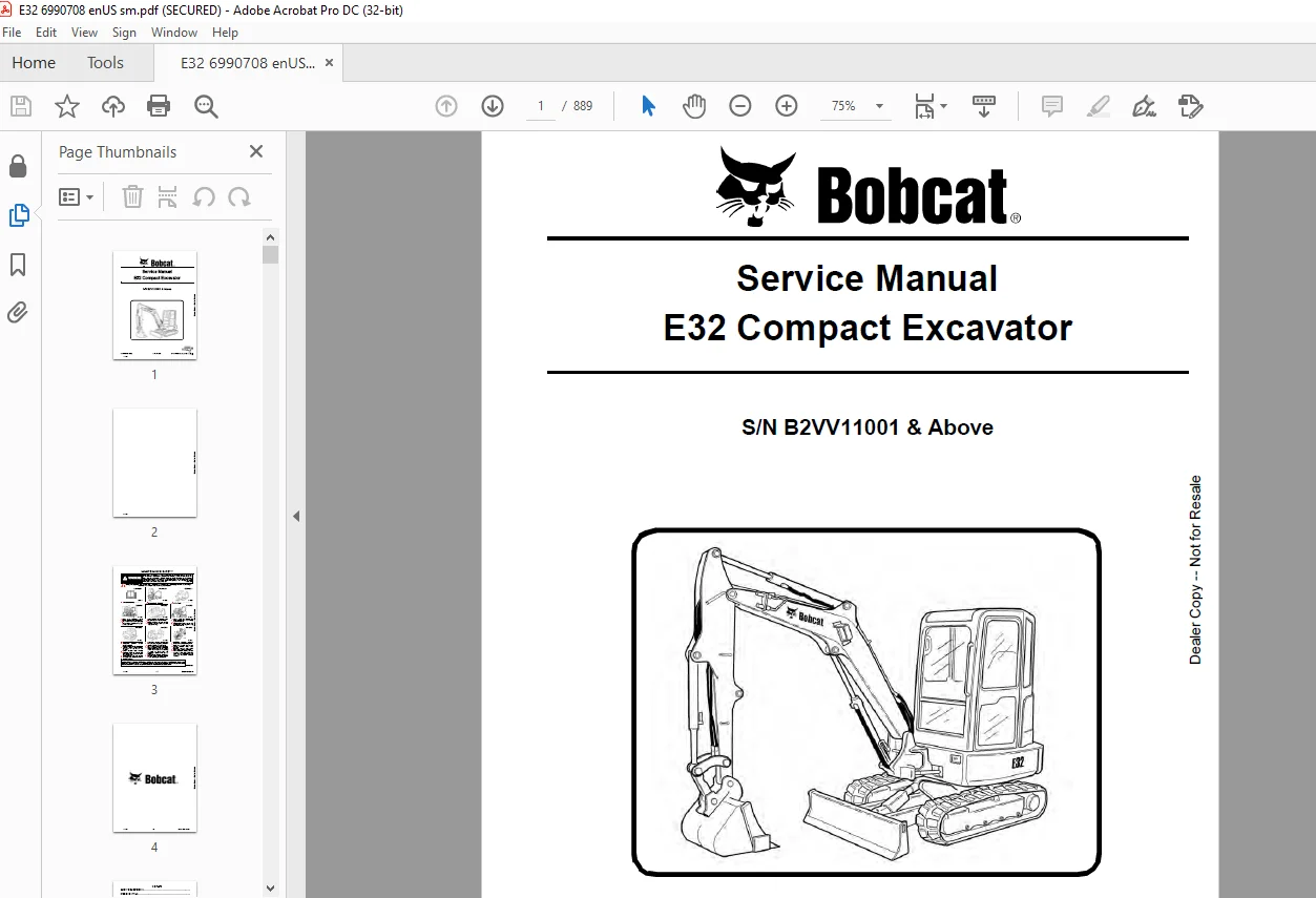
Bobcat Compact Excavator E32 Service Manual 6990708 (07-20) – PDF DOWNLOAD
S/N B2VV11001 & Above
Description
Bobcat Compact Excavator E32 Service Manual 6990708 (07-20) – PDF DOWNLOAD
FILE DETAILS:
Bobcat Compact Excavator E32 Service Manual 6990708 (07-20) – PDF DOWNLOAD
Language : English
Pages : 889
Downloadable : Yes
File Type : PDF
Size: 31.5 MB
DESCRIPTION:
Bobcat Compact Excavator E32 Service Manual 6990708 (07-20) – PDF DOWNLOAD
S/N B2VV11001 & Above
FOREWORD
This manual is for the Bobcat excavator mechanic. It provides necessary servicing and adjustment procedures for the Bobcat excavator and its component parts and systems. Refer to the Operation & Maintenance Manual for operating instructions, starting procedure, daily checks, etc.
SAFETY INSTRUCTIONS
Instructions are necessary before operating or servicing machine. Read and understand the Operation & Maintenance Manual, Operator’s Handbook and signs (decals) on machine. Follow warnings and instructions in the manuals when making repairs, adjustments or servicing. Check for correct function after adjustments, repairs or service. Untrained operators and failure to follow instructions can cause injury or death.
The following publications provide information on the safe use and maintenance of the Bobcat machine and attachments:
- The Delivery Report is used to assure that complete instructions have been given to the new owner and that the machine is in safe operating condition.
- The Operation & Maintenance Manual delivered with the machine or attachment contains operating information as well as routine maintenance and service procedures. It is a part of the machine and can be stored in a container provided on the machine. Replacement Operation & Maintenance Manuals can be ordered from your Bobcat dealer.
- Machine signs (decals) instruct on the safe operation and care of your Bobcat machine or attachment. The signs and their locations are shown in the Operation & Maintenance Manual. Replacement signs are available from your Bobcat dealer.
- An Operator’s Handbook fastened to the operator cab. It’s brief instructions are convenient to the operator. The handbook is available from your dealer in an English edition or one of many other languages. See your Bobcat dealer for more information on translated versions.
- The AEM Safety Manual delivered with the machine gives general safety information.
- The Service Manual and Parts Manual are available from your dealer for use by mechanics to do shoptype service and repair work.
IMAGES PREVIEW OF THE MANUAL:
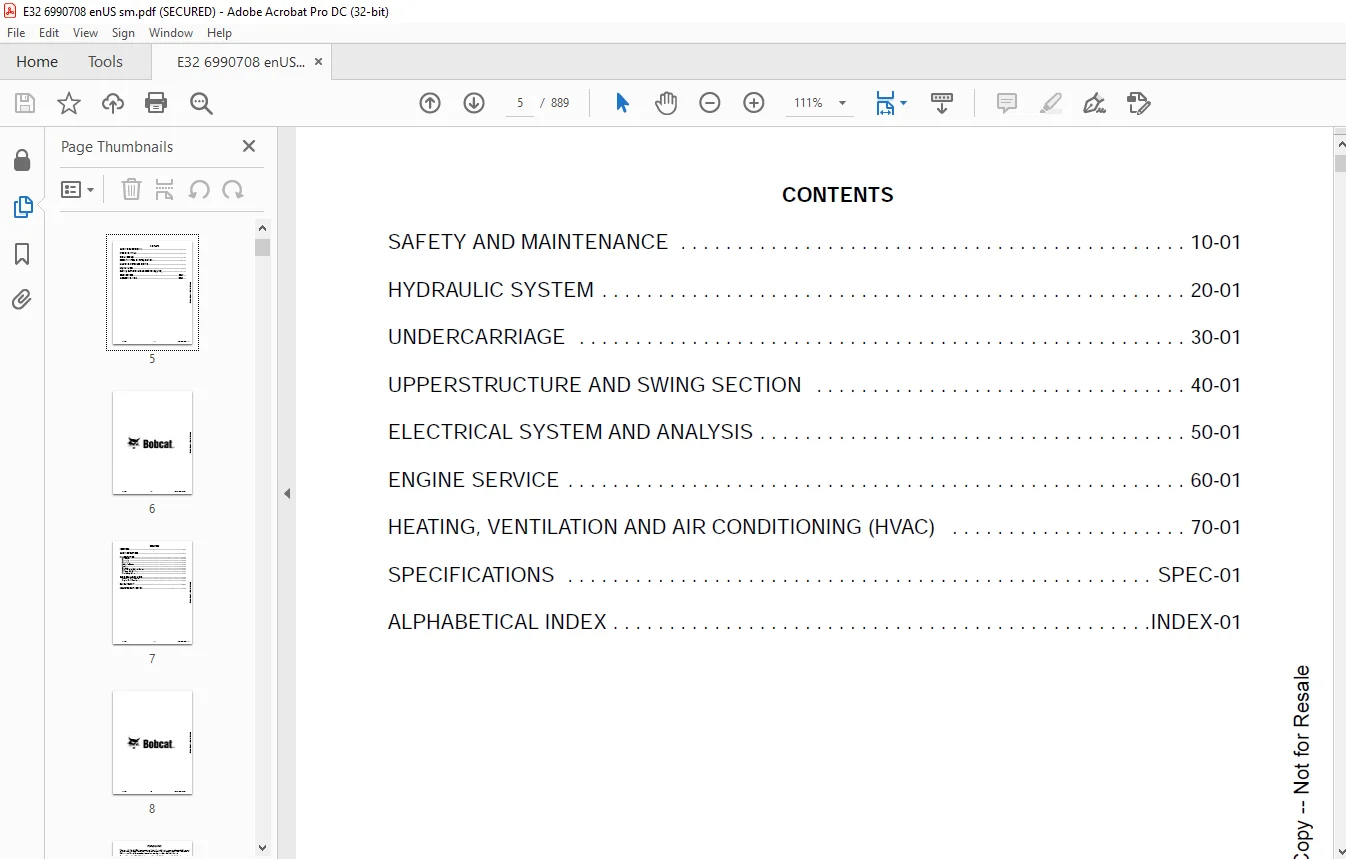
TABLE OF CONTENTS:
Bobcat Compact Excavator E32 Service Manual 6990708 (07-20) – PDF DOWNLOAD
MAINTENANCE SAFETY 3
CONTENTS 5
FOREWORD 7
FOREWORD 9
SAFETY INSTRUCTIONS 11
FIRE PREVENTION 13
Maintenance 13
Operation 13
Electrical 13
Hydraulic System 13
Fueling 13
Starting 13
Spark Arrester Exhaust System 13
Welding And Grinding 14
Fire Extinguishers 14
SERIAL NUMBER LOCATIONS 15
Excavator Serial Number 15
Engine Serial Number 15
DELIVERY REPORT 16
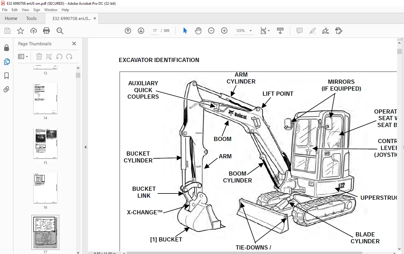
EXCAVATOR IDENTIFICATION 17
SAFETY AND MAINTENANCE 19
LIFTING AND BLOCKING THE EXCAVATOR 23
Procedure 23
LIFTING THE EXCAVATOR 25
Procedure 25
OPERATOR CAB (ROPS / TOPS) 27
Description 27
Cab Door 28
Front Window 29
Front Wiper 30
Window Washer Reservoir 30
Right Side Window 31
OPERATOR CANOPY (ROPS / TOPS) 33
Description 33
TRANSPORTING THE EXCAVATOR ON A TRAILER 35
Loading And Unloading 35
Fastening 36
TAILGATE 37
Opening And Closing 37
Adjusting The Latch 37
RIGHT SIDE COVER 39
Opening And Closing 39
SERVICE SCHEDULE 41
Maintenance Intervals 41
AIR CLEANER SERVICE 43
Daily Check 43
Replacing The Filters 43
CAB FILTERS 45
Cleaning And Maintenance 45
ENGINE COOLING SYSTEM 47
Cleaning 47
Checking Level 48
Removing And Replacing Coolant 49
FUEL SYSTEM 51
Fuel Specifications 51
Biodiesel Blend Fuel 51
Filling The Fuel Tank 52
Fuel Filters 53
Removing Air From The Fuel System 54
Draining The Fuel Tank 54
ENGINE LUBRICATION SYSTEM 55
Checking And Adding Engine Oil 55
Engine Oil Chart 55
Removing And Replacing Oil And Filter 56
HYDRAULIC SYSTEM 57
Checking And Adding Hydraulic Fluid 57
Hydraulic / Hydrostatic Fluid Chart 58
Removing And Replacing Hydraulic Filters 59
Removing And Replacing The Hydraulic Fluid 61
LUBRICATION OF THE HYDRAULIC EXCAVATOR 63
Lubrication Locations 63
PIVOT PINS 67
Inspection And Maintenance 67
TRAVEL MOTOR 69
Checking And Adding Oil 69
Removing And Replacing Oil 69
EMERGENCY EXIT 71
Right Side Rear Window 71
Front Window 71
SEAT BELT 73
Inspection And Maintenance 73
CONTROL CONSOLE LOCKOUTS 75
Inspection And Maintenance 75
TOWING THE EXCAVATOR 77
Procedure 77
REMOTE START TOOL KIT – MEL1563 79
Remote Start Tool Kit – MEL1563 79
Service Tool Harness Control – MEL1565 80
Service Tool Harness Communicator – MEL1566 81
REMOTE START TOOL (SERVICE TOOL) KIT – 7217666 83
Description 83
Remote Start Tool (Service Tool) – 7022042 84
Excavator Service Tool Harness – 6689747 85
Computer Service Tool Harness – 6689746 86
HYDRAULIC SYSTEM 87
HYDRAULIC / HYDROSTATIC SCHEMATICS 93
HYDRAULIC SYSTEM INFORMATION 95
Glossary Of Hydraulic / Hydrostatic Symbols 95
Troubleshooting The Hydraulic Circuit 98
Troubleshooting The Cylinder Circuit 99
Troubleshooting The Swing (Upperstructure Slew) Circuit 100
Troubleshooting The Travel Circuit 101
CYLINDER (BOOM) 103
Testing 103
Removal And Installation 105
Parts Identification 108
Disassembly 109
Assembly 112
CYLINDER (ARM) 117
Testing 117
Removal And Installation 119
Parts Identification 121
Disassembly 122
Assembly 124
CYLINDER (BOOM SWING) 129
Testing 129
Removal And Installation 131
Parts Identification 134
Disassembly 135
Assembly 137
CYLINDER (BUCKET) 141
Testing 141
Removal And Installation 142
Parts Identification 144
Disassembly 145
Assembly 147
CYLINDER (BLADE) 151
Testing 151
Removal And Installation 153
Parts Identification 154
Disassembly 155
Assembly 157
CYLINDER (CLAMP) 161
Testing 161
Removal And Installation 162
Parts Identification 164
Disassembly 165
Assembly 168
CYLINDER (EXTENDABLE ARM) 173
Testing 173
Parts Identification 175
Disassembly 176
Assembly 179
VALVE (MAIN RELIEF) 183
Description 183
VALVE (PORT RELIEF) 185
Testing And Adjusting Port Relief Valve Pressure 185
VALVE (CROSS PORT RELIEF) 187
Testing 187
Removal And Installation 189
Cross Port Relief Valve Disassembly And Assembly 189
VALVE (PILOT PRESSURE RELIEF) 191
Testing And Adjusting The Pilot Pressure Relief Valve 191
HYDRAULIC CONTROL VALVE 193
Description 193
Removal And Installation 193
Parts Identification 198
Disassembly 199
Assembly 205
Inlet Valve Section Disassembly And Assembly 209
Boom Swing Valve Section Disassembly And Assembly 211
Slew Valve Section Disassembly And Assembly 214
Blade Valve Section Disassembly And Assembly 215
Right And Left Travel Valve Section Disassembly And Assembly 218
Boom Valve Section Disassembly And Assembly 220
Auxiliary, Arm, Bucket And Angle Blade Valve Section Disassembly And Assembly 224
Outlet Valve Section Disassembly And Assembly 226
HYDRAULIC PUMP 229
Hydraulic Pump Work Sheet 229
Pump Testing 231
Description 239
Removal And Installation 239
Coupler Removal And Installation 240
Hydraulic Pump Startup 241
Gear Pump Disassembly And Assembly 242
Piston Pump Parts Identification 244
Piston Pump Disassembly And Assembly 245
MANIFOLD ASSEMBLY / ACCUMULATOR 257
Description 257
Removal And Installation 257
Parts Identification 259
Disassembly And Assembly 260
TRAVEL MOTOR 267
Removal And Installation 267
Parts Identification Hydraulic Motor 268
Parts Identification Gear Reduction Hub 269
Disassembly 270
Assembly 284
SWIVEL JOINT 301
Removal And Installation 301
Parts Identification Earlier Model Swivel 303
Parts Identification Later Model Swivel 304
Disassembly And Assembly 305
SWING MOTOR 307
Removal And Installation 307
Parts Identification 308
Disassembly And Assembly 309
SWING MOTOR (DRIVE CARRIER) 315
Removal And Installation 315
Parts Identification 316
Disassembly And Assembly 317
CONTROL PATTERN SELECTOR VALVE 323
Removal And Installation 323
Parts Identification 324
Disassembly And Assembly 325
RIGHT CONTROL LEVER (JOYSTICK) 327
Testing 327
Handle Removal And Installation 328
Joystick Assembly Removal And Installation 330
Parts Identification 331
Disassembly 332
Assembly 336
LEFT CONTROL LEVER (JOYSTICK) 341
Testing 341
Handle Removal And Installation 342
Joystick Assembly Removal And Installation 344
Parts Identification 345
Disassembly 346
Assembly 350
HYDRAULIC FILTER MOUNT 355
Removal And Installation 355
HYDRAULIC RESERVOIR 357
Removal And Installation 357
OIL COOLER 359
Removal And Installation 359
DIRECT TO TANK VALVE 361
Removal And Installation 361
BLADE CONTROL LEVER 363
Handle Removal And Installation 363
Removal And Installation 365
Parts Identification 367
Disassembly And Assembly 368
CASE DRAIN FILTER MOUNT 373
Removal And Installation 373
TRAVEL CONTROL VALVE 375
Removal And Installation 375
Parts Identification 376
Disassembly And Assembly 377
REMOVING AIR FROM THE HYDRAULIC SYSTEM 383
Procedure 383
HYDRAULIC X-CHANGE MANIFOLD (EARLIER MODEL) 385
Removal And Installation 385
Parts Identification 386
Disassembly And Assembly 387
HYDRAULIC X-CHANGE MANIFOLD (LATER MODEL) 391
Removal And Installation 391
Parts Identification 392
Disassembly And Assembly 393
SECONDARY AUXILIARY VALVE (EARLIER MODEL) 399
Removal And Installation 399
Parts Identification 401
Disassembly And Assembly 402
SECONDARY AUXILIARY VALVE (LATER MODEL) 407
Removal And Installation 407
Parts Identification 409
Disassembly And Assembly 410
VALVE (BOOM LOCK) 413
Removal And Installation 413
VALVE (ARM LOCK) 415
Removal And Installation 415
UNDERCARRIAGE 417
BLADE 419
Removal And Installation 419
TRACK UNDERCARRIAGE COMPONENTS (RUBBER TRACK) 421
Description 421
Track Lug Height 421
Checking Tension 422
Adjusting Tension 423
Track Removal And Installation 425
Idler Removal And Installation 427
Parts Identification 428
Idler Disassembly 429
Idler Assembly 431
Track Tensioner Removal And Installation 434
Track Tensioner Parts Identification 435
Track Tensioner Disassembly And Assembly 436
Roller Removal And Installation 438
Sprocket Removal And Installation 439
TRACK UNDERCARRIAGE COMPONENTS (STEEL TRACK) 441
Description 441
Checking Tension 442
Adjusting Tension 443
Track Removal And Installation 445
Idler Removal And Installation 448
Idler Parts Identification 449
Idler Disassembly 450
Idler Assembly 452
Track Tensioner Removal And Installation 455
Track Tensioner Parts Identification 456
Track Tensioner Disassembly And Assembly 457
Roller Removal And Installation 459
Sprocket Removal And Installation 460
Guide Plate Removal And Installation 460
TRACK MAINTENANCE 461
Track Damage Identification 461
SWING CIRCLE GEAR 473
Swing Bearing Removal 473
Swing Bearing Installation 474
UPPERSTRUCTURE AND SWING SECTION 475
UPPERSTRUCTURE 479
Removal 479
Installation 481
ROPS CANOPY 483
Removal And Installation 483
CAB 487
Removal And Installation 487
Door Removal And Installation 490
Front Window Removal And Installation 491
Front Window Disassembly And Assembly 492
Front Window Adjustment 493
Right Side Rear Sliding Window Removal And Installation 495
Right Side Front Sliding Window Removal And Installation 495
Right Side Front And Rear Sliding Window Weather Strip Removal And Installation 496
Right Side Front And Rear Sliding Window Wiper Strip Removal And Installation 496
Glass Removal 497
Glass Installation 498
SEAT 503
Removal And Installation 503
Seat Mount Removal And Installation 504
RIGHT CONSOLE 505
Console Cover Removal And Installation 505
LEFT CONSOLE 511
Lower Console Cover Removal And Installation 511
Upper Console Cover Removal And Installation 512
Compression Spring Removal And Installation 515
Lock Lever Removal And Installation 517
Console Removal And Installation 517
LEFT UPPERSTRUCTURE COVER 519
Removal And Installation 519
RIGHT UPPERSTRUCTURE COVER 521
Removal And Installation 521
COUNTERWEIGHT 523
Removal And Installation 523
Long Arm Counterweight Removal And Installation 526
TRAVEL LEVERS AND PEDALS 527
Removal And Installation 527
Disassembly And Assembly 528
FLOOR MAT 529
Removal And Installation 529
FUEL TANK 531
Removal And Installation 531
Fuel Tank Fitting Removal And Installation 532
HORN 533
Removal And Installation 533
SWING FRAME 535
Removal And Installation 535
Boom Swing Frame Hose Routing 539
Bushing Removal 540
Bushing Installation 541
BOOM 543
Removal And Installation 543
ARM (STANDARD AND LONG) 545
Removal And Installation 545
Arm To Boom Bushing Removal And Installation 546
Arm To Bucket And Bucket Link Bushing Removal And Installation 547
ARM (EXTENDABLE) 549
Removal And Installation 549
Arm To Boom Bushing Removal And Installation 550
Arm To Bucket Bushing Removal And Installation 551
Disassembly And Assembly 552
Shimming Procedure 560
BUCKET 561
Bucket Teeth Removal And Installation 561
Bucket Side Cutting Edge Removal And Installation 562
CLAMP 563
Removal And Installation 563
TAILGATE 565
Removal And Installation 565
Latch Removal And Installation 566
X-CHANGE 567
Removal And Installation 567
Disassembly 569
Assembly 570
X-CHANGE (HYDRAULIC) 573
Removal And Installation 573
Parts Identification 575
Disassembly 576
Assembly 581
QUICK COUPLER (KLAC™ SYSTEM) 589
Troubleshooting 589
Daily Inspection 589
Removal And Installation 590
Parts Identification 592
Disassembly 593
Assembly 594
QUICK COUPLER (LEHNHOFF® SYSTEM) 597
Troubleshooting 597
Daily Inspection 597
Removal (MS03 And MS08) 598
Installation (MS03 And MS08) 599
Parts Identification (MS03) 600
Disassembly And Assembly (MS03) 601
Parts Identification (MS08) 602
Disassembly (MS08) 603
Assembly (MS08) 606
RIGHT SIDE COVER 611
Removal And Installation 611
Latch Removal And Installation 612
Latch Adjustment 613
TOOL BOX 615
Removal And Installation 615
ELECTRICAL SYSTEM AND ANALYSIS 617
ELECTRICAL SCHEMATICS 619
ELECTRICAL SYSTEM INFORMATION 622
Troubleshooting Chart 622
Description 623
Fuse And Relay Location / Identification 623
BATTERY 626
Servicing 626
Removal And Installation 627
Using A Booster Battery (Jump Starting) 628
ALTERNATOR 630
Belt Adjustment 630
Belt Replacement 630
Charging System Inspection 630
Alternator Voltage Testing 631
Low Voltage Testing 632
High Voltage Testing 632
Removal And Installation 633
Parts Identification 635
STARTER 636
Testing 636
Removal And Installation 637
Parts Identification 638
LIGHTS 640
Removal And Installation 640
Boom Light Removal And Installation 641
Boom Light Bulb Replacement 641
MAGNETIC LOCKOUT SENSOR 642
Removal And Installation 642
FUEL LEVEL SENDER 644
Removal And Installation 644
Testing 645
DIAGNOSTIC SERVICE CODES 646
Viewing Service Codes 646
Service Codes List 647
CONTROL PANEL SETUP 652
Panel Setup (Deluxe Instrument Panel) 652
Password Setup (Keyless Start Panel) 658
Password Setup (Deluxe Instrument Panel) 659
Maintenance Clock 661
INSTRUMENT PANEL 666
Removal And Installation 666
CONTROLLER 668
Description 668
Gateway Controller Removal And Installation 669
Auxiliary Controller Removal And Installation 671
KEY SWITCH 672
Removal And Installation 672
WIPER MOTOR 674
Removal And Installation 674
MOTION ALARM SYSTEM 676
Description 676
Inspecting 676
Adjusting Switch Position 677
SERVICE PC (LAPTOP COMPUTER) 678
Connecting The Remote Start Tool 678
Connecting Remote Start Tool (Service Tool) 678
SHUT-OFF SWITCH 680
Description 680
Removal And Installation 681
TRAVEL MOTOR AUTO-SHIFT 684
Auto-Shift Drive System (If Equipped) 684
Troubleshooting 685
ENGINE SPEED CONTROL 688
Removal And Installation 688
AUTO IDLE PRESSURE SENSOR 690
Description 690
Removal And Installation 691
ENGINE SERVICE 692
ENGINE INFORMATION 696
Description 696
Specifications 697
Sensor Location 699
Torque Values 705
Troubleshooting 707
Engine Removal And Installation 709
DIESEL OXIDATION CATALYST (DOC) 718
Removal And Installation 718
AIR CLEANER 720
Housing Removal And Installation 720
ENGINE COOLING SYSTEM 722
Radiator Removal And Installation 722
Fan Removal And Installation 726
Water Pump Removal And Installation 727
Thermostat Housing Removal And Installation 728
Testing The Thermostat 729
LUBRICATION SYSTEM 730
Description 730
Oil Pan Removal And Installation 731
Oil Pump Removal And Installation 732
Oil Pump Relief Valve Description 733
Oil Pump Relief Valve Removal And Installation 733
Oil Cooler Removal And Installation 734
Oil Filter Head Removal And Installation 735
Oil Cooler Bypass Description 736
Oil Cooler Bypass Removal And Installation 736
FUEL SYSTEM 738
Description 738
Transfer Pump / High Pressure Pump Removal And Installation 739
Fuel Cooler Removal And Installation 743
Fuel Bypass Valve Removal And Installation 744
Fuel Recirculation Valve Removal And Installation 745
Fuel Injector Removal And Installation 746
Removing Air From The Fuel System 748
CYLINDER HEAD 750
Glow Plugs Testing 750
Glow Plug Removal And Installation 751
Valve Clearance Adjustment 752
Cylinder Head Removal And Installation 754
Cylinder Head Disassembly And Assembly 758
Cylinder Head Inspection 759
Cylinder Head Top Clearance 760
Valve Step Height 761
Valve Stem Height 761
Valve Guide 762
Valve 762
Valve Spring 763
Rocker Arm Shaft Disassembly And Assembly 764
Rocker Arm Shaft Inspection 765
Push Rod Inspection 765
CRANKSHAFT AND PISTONS 766
Piston And Connecting Rod Removal And Installation 766
Piston And Connecting Rod Inspection 767
Crankshaft Removal And Installation 769
Cylinder Block Inspection 772
Crankshaft Inspection 774
Connecting Rod Inspection 774
Engine Component Class 775
CAMSHAFT 778
Removal And Installation 778
Inspecting 779
GEARCASE 782
Gearcase Cover Removal And Installation 782
Gear Backlash 783
Gear Timing 784
Idle Gear Removal And Installation 785
Idle Gear Inspection 785
TURBOCHARGER 786
Description 786
Removal And Installation 786
Inspection 788
FLYWHEEL AND HOUSING 790
Hydraulic Pump Coupler Removal And Installation 790
Flywheel Removal And Installation 792
Ring Gear Removal And Installation 792
EXHAUST GAS RECIRCULATION (EGR) SYSTEM 794
Valve Removal And Installation 794
Cooler Removal And Installation 794
INTERCOOLER 796
Description 796
Removal And Installation 796
HEATING, VENTILATION AND AIR CONDITIONING (HVAC) 798
AIR CONDITIONING SYSTEM FLOW 800
Description 800
Chart 801
Components 802
Safety Equipment 805
REGULAR MAINTENANCE 806
Cab Filters 806
Air Conditioning Compressor Belt Adjustment 808
Air Conditioning Compressor Belt Replacement 808
Condenser 809
Air Conditioning Lubrication 810
Evaporator / Heater Coil 810
Air Conditioning Service Chart 811
TROUBLESHOOTING 812
Blower Motor Does Not Operate 812
Blower Motor Operates Normally, But Air Flow Is Insufficient 812
Insufficient Cooling Although Air Flow And Compressor Operation Are Normal 812
The Compressor Operates Improperly Or Not At All 812
Gauge Pressure Related Troubleshooting 813
Temperature / Pressure Chart 814
Poor A/C Performance 815
HVAC Repair And Leaks 816
Electrical System 817
Engine Coolant Bypassing The Heater Valve 819
SYSTEM CHARGING AND RECLAMATION 820
Refrigerant Identification 820
Reclamation And Charging With Recovery / Charging Unit 822
COMPRESSOR 824
Removal And Installation 824
Oil 825
Oil Check 826
CONDENSER 828
Removal And Installation 828
RECEIVER / DRIER 830
Receiver / Drier Removal And Installation 830
Pressure Switch Removal And Installation 831
EVAPORATOR / HEATER UNIT 832
Removal And Installation 832
THERMOSTAT 834
Description 834
Removal And Installation 835
EXPANSION VALVE 838
Removal And Installation 838
EVAPORATOR COIL 840
Removal And Installation 840
HEATER COIL 842
Removal And Installation 842
BLOWER FAN 844
Removal And Installation 844
HEATER VALVE 846
Removal And Installation 846
HVAC DUCT 848
Removal And Installation 848
SPECIFICATIONS 850
EXCAVATOR SPECIFICATIONS 852
Machine Dimensions 852
Machine Dimensions – Standard Arm 853
Machine Dimensions – Long Arm 854
Machine Dimensions – Extendable Arm 855
Performance 856
Engine 856
Controls 857
Hydraulic System 857
Hydraulic Cylinders 858
Hydraulic Cycle Times 858
Drive System 858
Slew System 858
Undercarriage 858
Electrical 859
Capacities 859
Tracks 859
Ground Pressure 859
TECHNICAL SERVICE GUIDE SPECIFICATIONS 860
Engine 860
Engine Torques 860
Cooling System 860
Excavator Torques 860
TORQUE SPECIFICATION FOR BOLTS 862
Torque For General SAE Bolts 862
Torque For General Metric Bolts 863
HYDRAULIC CONNECTION SPECIFICATIONS 864
O-ring Face Seal Connection 864
Straight Thread O-ring Fitting 864
Tubelines And Hoses 865
Flare Fitting 865
O-ring Flare Fitting 866
Port Seal Fitting 868
Push To Connect Fittings 869
HYDRAULIC FLUID SPECIFICATIONS 872
Specifications 872
CONVERSIONS 874
Decimal And Millimeter Equivalent Chart 874
U S To Metric Conversion Chart 875
SERVICE TOOLS REQUIRED 876
Remote Start Tools 876
Hydraulic Tools 877
Engine Tools 880
Electrical Tools 882
General Tools 882
HVAC Tools 883
ALPHABETICAL INDEX 884
Questions? Email us: [email protected]
https://vimeo.com/841757256?share=copy
PLEASE NOTE:
- This is the SAME MANUAL used by the dealerships to diagnose your vehicle
- No waiting for couriers / posts as this is a PDF manual and you can download it within 2 minutes time once you make the payment.
- Your payment is all safe and the delivery of the manual is INSTANT – You will be taken to the DOWNLOAD PAGE.
- So have no hesitations whatsoever and write to us about any queries you may have : heydownloadss @gmail.com
S.M