Description
Bobcat CT1021 CT1025 Compact Tractor Service Manual 7371512 (10-19) – PDF DOWNLOAD
FILE DETAILS:
Bobcat CT1021 CT1025 Compact Tractor Service Manual 7371512 (10-19) – PDF DOWNLOAD
Language : English
Pages : 435
Downloadable : Yes
File Type : PDF
Size: 28.0 MB
DESCRIPTION:
Bobcat CT1021 CT1025 Compact Tractor Service Manual 7371512 (10-19) – PDF DOWNLOAD
CT1021 S/N B4VF11001 & Above
CT1025 S/N B4VG11001 & Above
FORWARD
This manual is for the Bobcat® compact tractor mechanic. It provides necessary servicing and adjustment procedures for the Bobcat compact tractor and its component parts and systems. Refer to the Operation & Maintenance Manual for operating instructions, starting procedure, daily checks, etc.
TABLE OF CONTENTS:
Bobcat CT1021 CT1025 Compact Tractor Service Manual 7371512 (10-19) – PDF DOWNLOAD
FORWARD 3
TABLE OF CONTENTS 5
SAFETY FIRST 7
For Safety 8
Alert Symbols 8
Safety Tips 9
Safety Gear 9
Work Place 9
Safety Instructions When
Preparing Tractor 10
Avoid Fires 10
Cautions When Handling the
Battery 11
Cautions for High Pressure Hoses 11
Use of Appropriate Tools and Equipment 12
Handling of Hazardous Material 12
Handling of Rotating Blade, Shaft and Driving Belt 13
Prevention of Scald 13
Disposal of Environmental Waste 14
Cautions When Handling Tires 14
Safety Decals 15
Location of Decals 15
GENERAL 17
IDENTIFICATION NUMBER 18
Tractor Serial Number Location 18
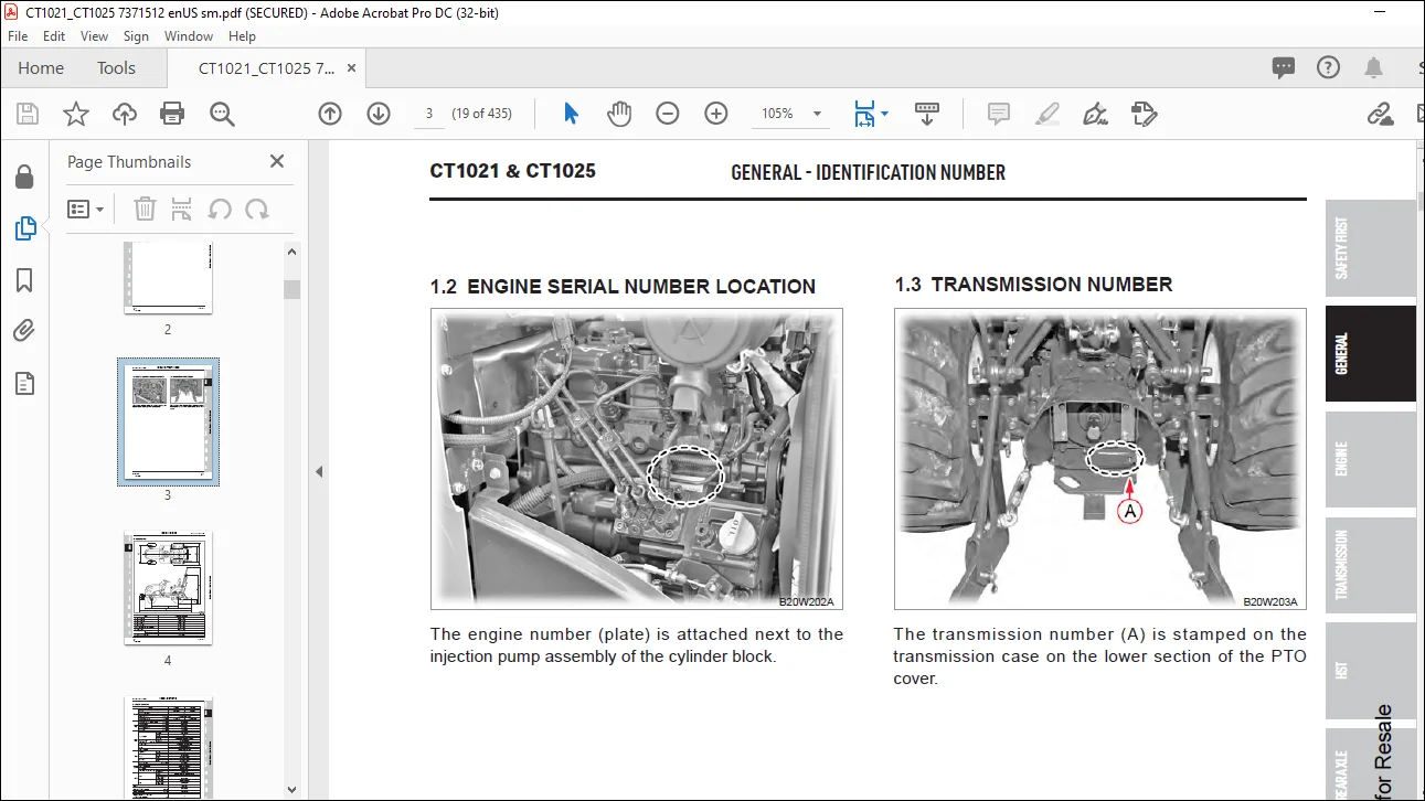
Engine Serial Number Location 19
Transmission Number 19
DIMENSIONS 20
SPECIFICATIONS 21
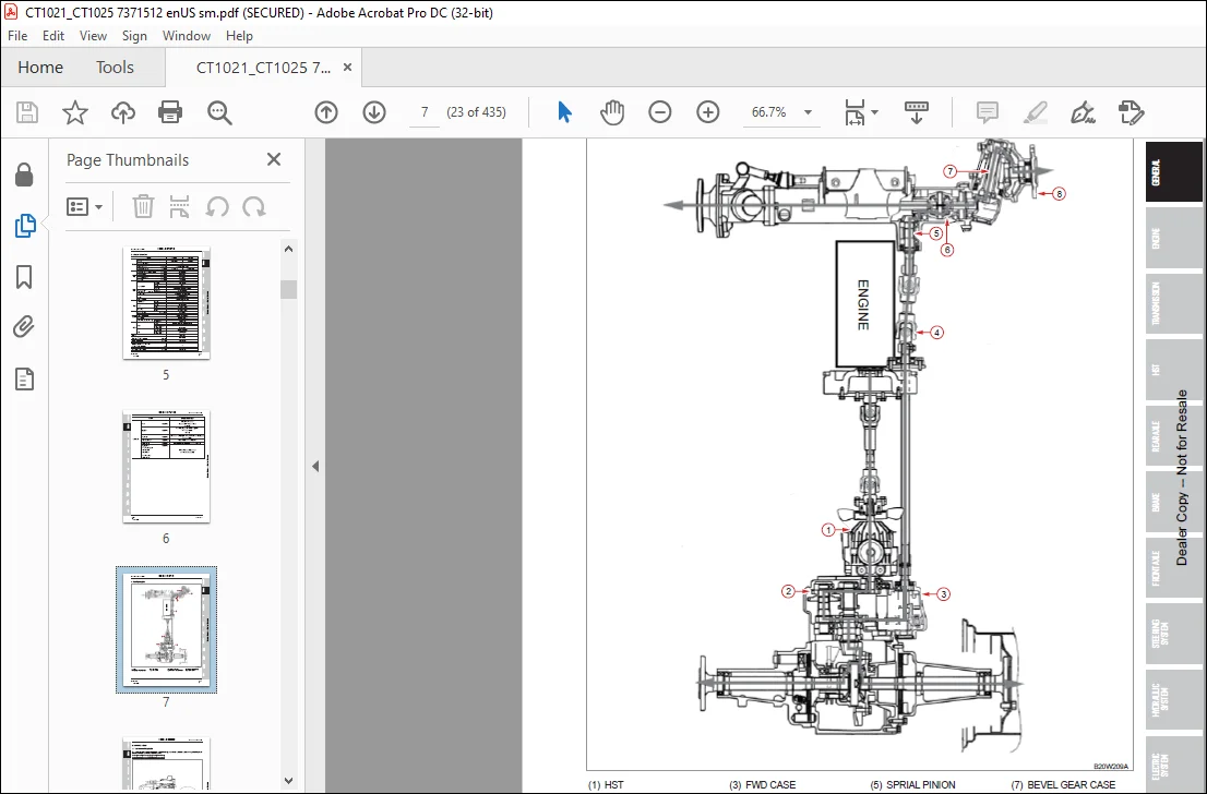
POWER FLOW 23
DRIVING SPEED 24
Gear Arrangement 24
Speed Ratio (Engine vs Rear Axle) 27
Rear Tire Rolling Circumference 27
Calculation of Driving Speed 27
Driving Speed Table 28
Reverse Driving Speed 28
RELATIVE SPEED RATIO OF FRONT WHEELS 29
Calculation For Relative Speed Ratio Of Front Wheels 29
How to Measure The Actual Rolling Circumference 32
MAINTENANCE SCHEDULE CHART 33
Maintenance Intervals 33
TIRES 35
Specified Inflation Pressure 35
Tightening Torque For Tire Bolts 35
TIGHTENING TORQUE 36
General Use Screws, Bolts And Nuts 36
Stud Bolts 36
American Standard Screws, Bolts And Nuts With UNC Or UNF Threads 37
UNIT CONVERSION TABLE 38
ENGINE 39
ENGINE IDENTIFICATION 41
Engine Decal (A) 41
Engine Number (B) 41
Engine Dimensions 42
SPECIFICATIONS 42
General Specifications 43
Servicing Specifications 44
TROUBLESHOOTING 49
EXPLODED VIEW OF ENGINE 51
Cylinder Block 51
Crankshaft, Piston 52
Oil Pump & Camshaft 53
Timing Gear Case, Governor 54
Cylinder Head, Exhaust Manifold 55
Oil Pan, Rear Plate, Starting Motor 56
Injection Pump, Injector 57
Rocker Arm Assy 58
Head Cover 59
Water Pump 60
NTE Components (CT1025) 61
SERVICING AND OPERATING 62
Engine Disassembly Order 68
Disasembly And Inspection of
Main Engine Parts 72
Rocker Arm Ass’y 72
Cylinder Head Ass’y 73
Cylinder Block 76
Piston and Piston Ring 77
Connecting Rod 79
Connecting Rod Metal 79
Bearing Holder 80
Crankshaft Bearing 81
Crankshaft 82
Flywheel and Ring Gear 83
Camshaft Ass’y 84
Timing Gear 84
Oil Flow 85
Oil Pump 86
Oil Filter 87
Water pump Assembly 87
Thermostat 87
Radiator 88
Fuel Filter 89
Governor 90
Injection Pump 90
Nozzle and Holder 91
Air Cleaner 92
Reassembly 93
Relief Valve Assembly with
O-ring 93
Crankshaft and Bearing
Holder Assembly 93
Oil Seal 93
Rear Plate 94
Flywheel 94
Piston and Connecting Rod Assembly 94
Suction Pipe and Suction Filter 95
Oil Pan 95
Oil Level Gauge and Gauge Guide 95
Front Plate 95
Camshaft Ass’y · TachometerShaft · Plate 96
Idle Gear · Oil Pump Ass’y 96
Timing Gear Case 97
Crankshaft Pulley 98
Injection Pump Assembly 98
Injection Timing Adjustment 99
Oil Filter 100
Engine Stop Solenoid 100
Tappet 100
Cylinder Head 100
Oil Pipe 101
Push Rod and Rocker Arm Ass’y 102
Valve Clearance Adjustment 102
Head Cover 103
Water Pump Ass’y, Radiator
Hose 103
Glow Plug · Connector 104
Oil Pressure Switch 104
Nozzle and Holder Ass’y 104
Return Pipe COMPL · InjectionPipe 105
Alternator Ass’y 105
Drive Gear Assembly and
Hydraulic Oil 105
V Belt · Fan Pulley · Cooling fan 106
�Exhaust Manifold and Muffler Assembly 106
ECU (Engine Control Unit) & Sensors (CT1025) 107
TRANSMISSION 109
SPECIFICATIONS 110
General Specifications 110
Tightening Torque For Major Components 110
Sealant And Adhesive Specifications 111
STRUCTURE AND OPERATING PRINCIPLE 112
Structure 112
Main Gear Shift & Shuttle System 113
Range Shift Section 114
PTO 115
PTO Clutch Pack 118
Calculation For Rear PTO And Mid PTO 118
Front Wheel Drive 119
TROUBLESHOOTING 121
EXPLODED VIEW OF TRANSMISSION 122
HI-LOW Gear 122
Bevel Pinoin Gear 123
PTO Gear 124
4WD Drive 125
4WD Joint 126
Auto 4WD (Optional) 127
SERVICING 128
Transmission Removal 128
FWD Case Removal 140
Transmission Case Disassembly 150
PTO Drive Section Disassembly 156
PTO Clutch Assembly – Disassembly 162
HST 165
SPECIFICATIONS 166
General 166
HST 166
Major Tightening Torque 166
OPERATING PRINCIPLE 167
STRUCTURE AND FUNCTION 169
Power Train 169
HST Components 170
Major HST Component Structure And Function 171
Circuit Diagram 171
Pump, Motor And Swash Plate 172
Charge Relief Valve 173
High Pressure Relief Valve 174
Inlet Check Valve (Anti-Cavitation Valve) 175
Operation Of HST 177
Neutral Status 177
Forward Driving 179
Reverse Driving 181
INSPECTION AND ADJUSTMENT 183
HST Neural Position Setting 183
HST Forward Pedal Travel Adjustment 184
Pressure Testing 185
High Pressure Relief Valves 185
TROUBLESHOOTING 189
EXPLODED VIEW OF HST 191
Main Shaft Joint 191
HST Pedal 192
ASSY, HST 193
SERVICING 194
HST Removal 194
HST Components Disassembly 195
REAR AXLE 199
SPECIFICATIONS 200
Transmission Fluid 200
Tightening Torques 200
OPERATING PRINCIPLE 201
Power Train Of Rear Axle 201
Principle Of Differential System 202
Differential Lock System 203
TROUBLESHOOTING 205
MEASUREMENT AND ADJUSTMENT 205
Backlash For Differential Pinion And Side Gear 205
Pre-load Of Taper Roller Bearing On Diff 206
Backlash For Spiral Bevel Pinion And Ring Gear 207
Tooth Contact Of Spiral Bevel 207
EXPLODED VIEW OF REAR AXLE 209
G260 Rear Differential System 209
G265 Rear Axle 210
SERVICING 211
Rear Axle Removal 211
Rear Differential System Removal 214
Rear Differential System Assembly Disassembly 216
BRAKE 219
SPECIFICATIONS 220
BASIC OPERATING PRINCIPLE 220
Basic Principle 220
Braking Force Forward / Reverse Driving 222
TROUBLESHOOTING 223
INSPECTION AND ADJUSTMENT 224
Brake Pedal Free Play 224
Brake Switch Setting (Optional) 225
Parking Brake Switch Adjustment (CT1025) 226
Brake Cam Lever Free Play 227
Brake Components Inspection 227
EXPLODED VIEW OF BRAKE 228
G250 Brake 228
G418 Brake Pedal 229
SERVICING 230
Brake Parts Removal 230
FRONT AXLE 233
SPECIFICATIONS 234
General Specifications 234
Sealant And Adhesive 234
Tightening Torque For Major Components 235
OPERATING PRINCIPLE 236
Power Transfer System For Front Axle 236
Differential System 237
Load Transfer 238
TROUBLESHOOTING 239
MEASUREMENT AND ADJUSTMENT 240
Toe In 240
Backlash For Spiral Bevel Pinion And Spiral Bevel Gear 240
Tooth Contact Of Spiral Bevel Gear 241
EXPLODED VIEW OF FRONT AXLE 242
Front Axle Support 242
Bevel Gear Case 243
Front Axle Case 244
Front Axle 245
SERVICING 246
Front Axle Removal 246
Front Axle Disassembly And
Assembly 248
Steering Cylinder Removal 248
Front Axle Cover Disassembly 249
Bevel Gear Case Disassembly 250
Front Differential System Disassembly 251
Bevel Pinion Shaft Removal 253
STEERING SYSTEM 255
SPECIFICATIONS 256
Steering Cylinder 256
Steering Unit 256
Tightening Torque For Main Components 256
OPERATING PRINCIPLE 257
Hydraulic Circuit For Steering Operation 257
Operating Principle 258
Operation 259
Structure 263
TROUBLESHOOTING 266
INSPECTION AND ADJUSTMENT 267
Steering Relief Opening Pressure 267
Relief Valve Pressure Adjustment 268
EXPLODED VIEW OF STEERING SYSTEM 270
G335 Steering Cylinder 270
G422 Steering & Hand Accel 271
G615 Power Steering Unit 272
SERVICING 273
Steering Cylinder 273
Steering Unit Removal 275
Disassembly of Power Steering Unit Components 276
Inspection 279
Installation 279
Steering Hydraulic Tube Location 283
HYDRAULIC SYSTEM 285
SPECIFICATIONS 286
OPERATING PRINCIPLE 287
Schematic And Circuit Diagram 287
Hydraulic Schematic And Basic Operation 287
Components 295
Hydraulic Pump 295
Oil Filter 296
Auxiliary Double Acting Valve (Optional) 298
HPL Valve (Hyd Power Lift) 304
MOWER LIFT LINKAGE 311
HYDRAULIC SCHEMATICS 289
TROUBLESHOOTING 312
INSPECTION AND ADJUSTMENT 313
Main System Relief Valve 313
Aux Double Acting Valve Pressure
(OPTIONAL) 314
Feedback Plate Adjustment 314
EXPLODED VIEW OF HYDRAULIC SYSTEM 317
HYD CYLINDER 317
FILTER AND PIPE 318
GEAR PUMP 319
CONTROL (HPL) VALVE 320
DOUBLE ACTING VALVE 321
REAR HYDRAULIC PIPE (Option) 322
FRONT HYDRAULIC PIPE (Option) 323
SHUT-OFF VALVE (Option) 324
SERVICING 325
Hydraulic Cylinder Removal & Disassembly 325
Double Acting Valve (Optional)
Disassembly And Assembly 327
Double Acting Valve Components Removal and Installation 329
Gear Pump Disassembly 332
Control Valve Disassembly And Assembly 333
Control Valve Components Disassembly 335
Assembly 340
ELECTRIC SYSTEM 343
ELECTRICAL SCHEMATICS 345
SPECIFICATIONS 347
GENERAL INFORMATION 0
Battery 353
Symbols For Electric Components 354
Wiring Color Identification 355
Fuse 356
Inspection 356
Cause For Blown Fuse 356
Electric Device Diagnosis 357
OPERATING PRINCIPLE 358
When Ignition Switch Is In “OFF” Position 358
When Ignition Switch Is In “ACC” Position 359
When Ignition Switch Is In Turned To “ON” Position 360
When Ignition Switch Is In Turned To And Held In “GL” (Manual Preheat)
Position 363
When Ignition Switch Is In Turned To “ST” Position 364
Operating Principle Of Preheat Controller 366
ECU 368
Fuse Box 371
Slow-Blow Fuse 371
CHECKING ELECTRIC PARTS 371
Key Switch 372
Combination Switch 373
Flasher Unit 375
30/20A 5p Relay 375
Hazard Warning Flasher Switch 376
Glow Plug 377
Engine Stop Solenoid (CT1021) 378
ECU (CT1025) 379
Actuator (CT1025) 385
Pressure Sensor (CT1025) 385
Speed Sensor (MPU: Magnet Pick Up)(CT1025) 386
Parking Brake Micro Switch 387
Brake Switch (OPTIONAL) 387
Instrument Panel 388
Components And Locations 388
Circuit Diagram For Instrument Panel 390
Gauges And Indicators 391
Cluster Lamp Test 394
Oil Pressure Switch 395
Dual Temperature Switch 395
Fuel Sensor 396
Alternator 397
Preheat Controller 398
Neutral Safety Switch 401
PTO Clutch Safety Switch 401
Head Lamp 402
Turn Signal Lamp 403
Tail Lamp 403
TROUBLESHOOTING 404
When the Engine Cannot Be Started 404
When the System Is Not Charged 406
When the System Is Not Preheated Manually (CT1021) 408
When the System Is Not Preheated Automatically 410
When The Cruise System Cannot Be Operated (OPTIONAL) 412
When The Head Lamp Cannot Be Operated 414
Tachometer Operation With The Engine Running 416
Fuel Gauge Operation 417
Temperature Gauge Operation 419
Hour Meter Operation 421
EXPLODED VIEW OF ELECTRIC SYSTEM 422
Engine Electrical System 422
Transmission Electrical System 423
Chassis Electrical System 424
Cruise (Optional) 425
Wire Harness 426
Light 427
Working Lamp 428
INDEX 429
IMAGES PREVIEW OF THE MANUAL:


Customer Support: [email protected]
https://vimeo.com/841428511?share=copy
PLEASE NOTE:
- This is the SAME exact manual used by your dealers to fix your vehicle.
- The same can be yours in the next 2-3 mins as you will be directed to the download page immediately after paying for the manual.
- Any queries / doubts regarding your purchase, please feel free to contact [email protected]
s.m