Bobcat CT225, CT230 Compact Tractor Service Manual 6986526(09-15) – PDF DOWNLOAD
$34.95
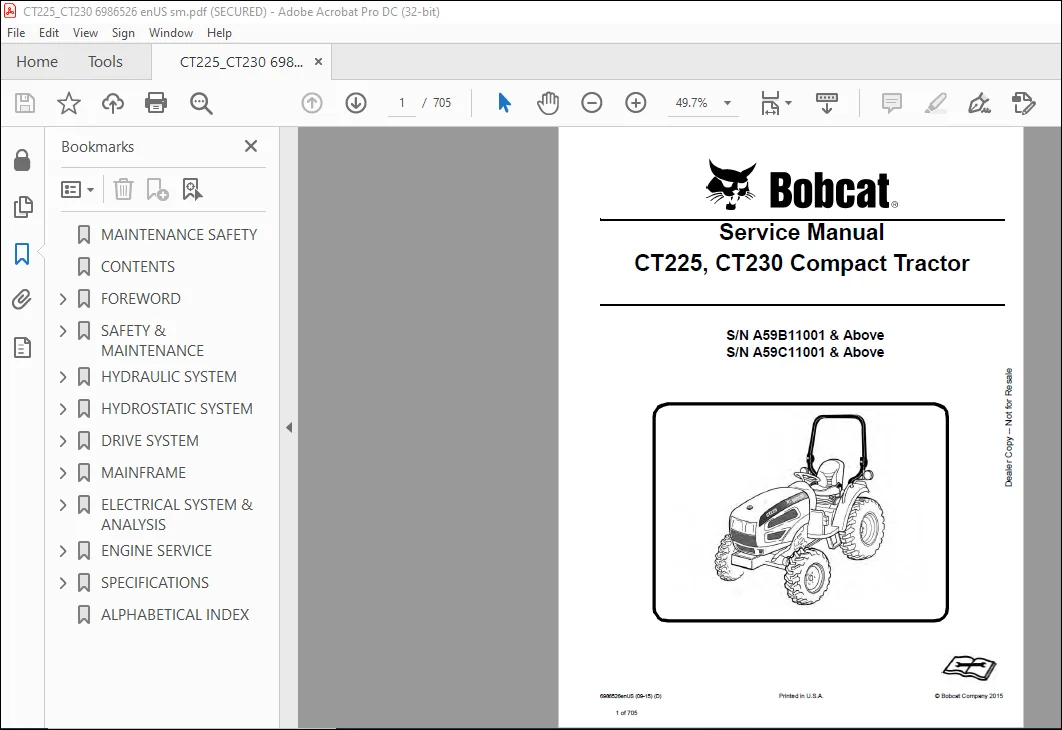
Bobcat CT225, CT230 Compact Tractor Service Manual 6986526(09-15) – PDF DOWNLOAD
S/N A59B11001 & Above
S/N A59C11001 & Above
Description
Bobcat CT225, CT230 Compact Tractor Service Manual 6986526(09-15) – PDF DOWNLOAD
FILE DETAILS:
Bobcat CT225 CT230 Compact Tractor Service Manual 6986526(09-15) – PDF DOWNLOAD
Language : English
Pages : 705
Downloadable : Yes
File Type : PDF
Size:20.1 MB
DESCRIPTION:
Bobcat CT225 CT230 Compact Tractor Service Manual 6986526(09-15) – PDF DOWNLOAD
FOREWORD
This manual is for the Bobcat compact tractor mechanic. It provides necessary servicing and adjustment procedures for the Bobcat compact tractor and its component parts and systems. Refer to the Operation & Maintenance Manual for operating instructions, starting procedure, daily checks, etc.
SAFETY INSTRUCTIONS:
Instructions are necessary before operating or servicing machine. Read Operation & Maintenance Manual,
Handbook and signs (decals) on machine. Follow warnings and instructions in the manuals when making
repairs, adjustments or servicing. Check for correct function after adjustments, repairs or service. Failure
to follow instructions can cause injury or death.
The following publications provide information on the safe use and maintenance of the loader and attachments:
• The Delivery Report is used to assure that complete instructions have been given to the new owner and that the machine
is in safe operating condition.
• The Operation & Maintenance Manual delivered with the loader gives operating information as well as routin e
maintenance and service procedures. It is a part of the loader and must stay with the machine when it is sold. Replacement
Operation & Maintenance Manuals can be ordered from your Bobcat loader dealer.
• The loader has machine signs (decals) which instruct on the safe operation and care. The signs and their locations are
shown in the Operation & Maintenance Manual. Replacement signs are available from your Bobcat loader dealer.
• The loader has a plastic Operator’s Handbook fastened to the operator cab. Its brief instructions are convenient to the
operator. The Handbook is available from your dealer in an English edition or one of many other languages. See your
Bobcat dealer for more information on translated versions.
• The EMI Safety Manual (available in Spanish) delivered with the loader gives general safety information.
• The Service Manual and Parts Manual are available from your dealer for use by mechanics to do shop–type service and
repair work.
• The Skid–Steer Loader Operator Training Course is available through your local dealer. This course is intended to provide
rules and practices for correct operation of the Bobcat loader. The course is available in English and Spanish version.
• The Bobcat Skid–Steer Loader Safety Video is available from your Bobcat Dealer.
TABLE OF CONTENTS:
Bobcat CT225 CT230 Compact Tractor Service Manual 6986526(09-15) – PDF DOWNLOAD
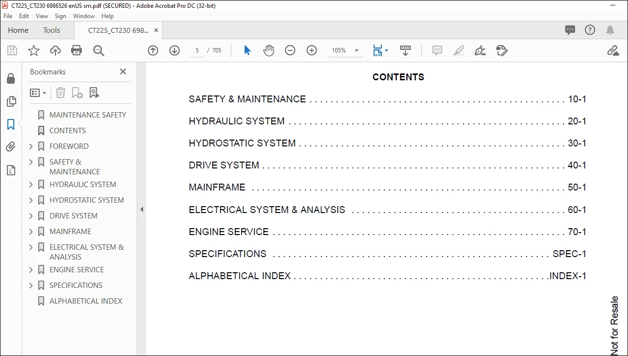
MAINTENANCE SAFETY 3
CONTENTS 5
FOREWORD 7
FOREWORD 9
SAFETY INSTRUCTIONS 11
Use Safety Rules 12
Safety Rules For Power Take-Off (PTO) Driven Implements 13
Compact Tractor Requirements and Capabilities 13
FIRE PREVENTION 14
Maintenance 14
Operation 14
Electrical 14
Hydraulic System 14
Fueling 14
Starting 14
Spark Arrester Exhaust System 14
Welding And Grinding 15
Fire Extinguishers 15
SERIAL NUMBER LOCATIONS 16
Compact Tractor Serial Number 16
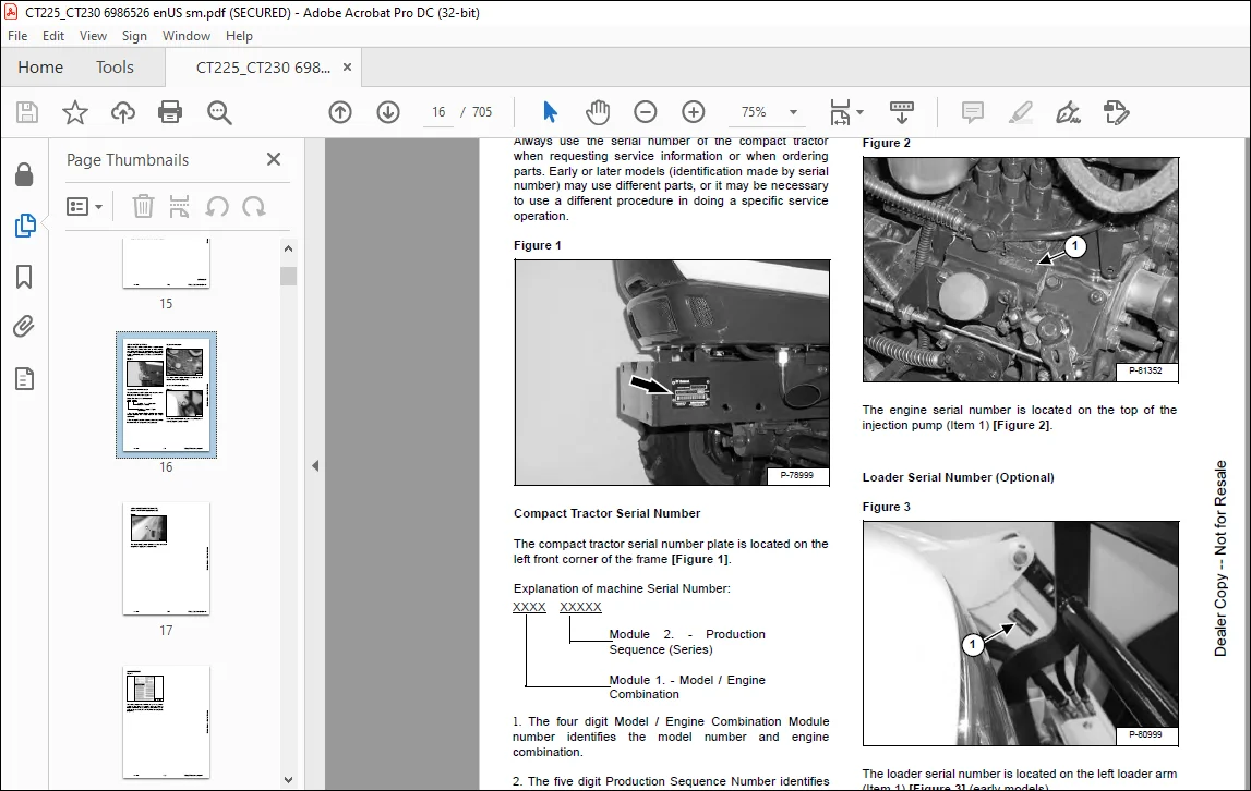
Engine Serial Number 16
Loader Serial Number (Optional) 16
DELIVERY REPORT 18
COMPACT TRACTOR IDENTIFICATION 19
COMPACT TRACTOR IDENTIFICATION (WITH OPTIONAL LOADER AND REAR BALLAST) 20
COMPACT TRACTOR IDENTIFICATION (WITH OPTIONAL THREE-POINT IMPLEMENT AND FRONT BALLAST) 21
SAFETY & MAINTENANCE 23
SUPPORTING THE COMPACT TRACTOR ON JACKSTANDS 27
Procedure 27
ENGINE COVER 29
Opening And Closing 29
SEAT BELT 31
Inspection And Maintenance 31
TRANSPORTING THE COMPACT TRACTOR ON A TRAILER 33
Loading And Unloading 33
Fastening 34
TOWING THE COMPACT TRACTOR 37
Procedure 37
AXLE TOE IN 39
Inspection And Maintenance 39
SERVICE SCHEDULE 41
Chart 41
AIR CLEANER SERVICE 43
Replacing Filter Element 43
AIR CLEANER SERVICE 44
ENGINE COOLING SYSTEM 45
Checking Level 45
Cleaning 46
Hoses And Clamps 46
Removing And Replacing Coolant 47
FUEL SYSTEM 49
Fuel Specifications 49
Biodiesel Blend Fuel 49
Filling The Fuel Tank 50
Fuel Filter 51
Removing Air From The Fuel System 52
Filling A Portable Fuel Container 52
ENGINE LUBRICATION SYSTEM 53
Checking And Adding Engine Oil 53
Engine Oil Chart 53
Removing And Replacing Oil And Filter 54
HYDRAULIC / HYDROSTATIC / TRANSMISSION SYSTEM 57
Checking And Adding Fluid 57
Transmission / Differential Fluid Chart 57
Removing And Replacing Hydraulic / Hydrostatic / Transmission Filters 58
Removing And Replacing Hydraulic / Transmission Fluid 59
Hoses And Clamps 59
FRONT AXLE 61
Checking And Adding Lubricant 61
Removing And Replacing Lubricant 62
Axle Pivot 62
SPARK ARRESTER MUFFLER 63
Cleaning Procedure 63
COMPACT TRACTOR STORAGE AND RETURN TO SERVICE 65
Storage 65
Return To Service 66
ALTERNATOR BELT 67
Belt Adjustment 67
Belt Replacement 67
LUBRICATING THE COMPACT TRACTOR 69
Lubrication Locations 69
TIRE MAINTENANCE 73
Front Wheel Nuts / Bolts 73
Rear Wheel Nuts / Bolts 73
Mounting 73
PIVOT PINS 75
Inspection And Maintenance 75
SAFETY INTERLOCK SYSTEM – NEUTRAL START 77
Inspection And Maintenance 77
SAFETY INTERLOCK SYSTEM – OPERATING 79
Inspection And Maintenance 79
PARKING BRAKE SYSTEM 81
Inspection And Maintenance 81
BRAKE SYSTEM 83
Inspection And Maintenance 83
Adjusting 84
TRAVEL CONTROL PEDAL 85
Inspection And Maintenance 85
Adjustment Procedure 85
CRUISE CONTROL 87
Inspection And Maintenance 87
Adjusting The Cruise Control Tension 87
CLUTCH SYSTEM 89
Inspection And Maintenance 89
Adjusting 90
Draining Water From Clutch Housing 91
BOB-TACH (HAND LEVER) 93
Inspection And Maintenance 93
HYDRAULIC SYSTEM 95
HYDRAULIC SCHEMATIC 99
HYDRAULIC SYSTEM INFORMATION 101
Glossary Of Hydraulic / Hydrostatic Symbols For Compact Tractors 101
Troubleshooting The Hydraulic Circuit 105
Troubleshooting The Joystick Valve Circuit 105
Troubleshooting The Power Lift Circuit 106
Troubleshooting The Steering Circuit 107
MAIN RELIEF VALVE 109
Testing Information 109
Testing And Adjusting The Main Relief Valve 109
HYDRAULIC PUMP 115
Removal And Installation 115
Parts Identification 118
Disassembly 119
Assembly 123
STEERING VALVE 127
Removal And Installation 127
Parts Identification 128
Disassembly 129
Inspection 134
Assembly 134
STEERING CYLINDER 141
Removal And Installation 141
Parts Identification 143
Disassembly And Assembly 144
RIGHT JOYSTICK (IF EQUIPPED) 145
Removal And Installation 145
Parts Identification 148
Disassembly And Assembly 149
Adjustment 151
RIGHT JOYSTICK VALVE (IF EQUIPPED) 153
Removal And Installation 153
Parts Identification 156
Disassembly 157
Inspection 161
Assembly 161
HYDRAULIC FILTER 165
Description 165
Filter Bracket Removal And Installation 165
OIL COOLER 167
Removal And Installation 167
THREE-POINT HITCH HOUSING 169
Removal And Installation 169
AUXILIARY CONTROL VALVE 171
Inlet Valve Section Disassembly And Assembly 171
No 1 Valve Section Parts Identification 174
No 1 Valve Section Disassembly And Assembly 175
No 2 Valve Section Parts Identification 181
No 2 Valve Section Disassembly And Assembly 182
ROCK SHAFT 189
Removal And Installation 189
Inspection 191
MLS VALVE 193
Removal And Installation 193
Parts Identification 194
Disassembly And Assembly 195
Adjustment 204
THREE-POINT CYLINDER 207
Disassembly And Assembly 207
Inspection 210
THREE POINT CYLINDER CONTROL 213
Disassembly And Assembly 213
CYLINDER (Lift) (EARLY MODELS) 219
Testing 219
Removal And Installation 219
Parts Identification 222
Disassembly 223
Assembly 225
CYLINDER (LIFT) (LATE MODELS) 229
Testing 229
Removal And Installation 229
Parts Identification 232
Disassembly 233
Assembly 235
CYLINDER (TILT) (EARLY MODELS) 239
Testing 239
Removal And Installation 239
Parts Identification 241
Disassembly 242
Assembly 244
CYLINDER (TILT) (LATE MODELS) 249
Testing 249
Removal And Installation 249
Parts Identification 251
Disassembly 252
Assembly 254
HYDROSTATIC SYSTEM 257
HYDROSTATIC SYSTEM INFORMATION 259
Troubleshooting Chart 259
HYDROSTATIC PUMP 261
Removal And Installation 261
Parts Identification 262
Disassembly 263
Inspection 275
Assembly 277
Hydrostatic Pump Start-Up 288
HYDROSTATIC PUMP TESTING 289
Charge Pressure Testing 289
Drive Relief Information 290
Forward Drive Relief Testing 291
Reverse Drive Relief Testing 292
TRAVEL PEDAL 293
Removal And Installation 293
DRIVE SYSTEM 295
SERVICE BRAKE 299
Troubleshooting Chart 299
Description 300
Brake Pedal Clearance Adjustment 300
Stop Switch Gap Adjustment 301
BRAKE PEDAL ASSEMBLY 303
Removal And Installation 303
DRIVESHAFT 307
Removal And Installation 307
AXLE CASE 309
Removal And Installation 309
Parts Identification 311
Disassembly And Assembly 312
BRAKE CASE 317
Removal And Installation 317
Parts Identification 319
Disassembly And Assembly 320
Inspection 323
TRANSMISSION 325
Troubleshooting Chart 325
Middle Case / Output Shaft Group Parts Identification 326
Middle Case / Output Shaft Group Disassembly 327
Middle Case / Output Shaft Group Inspection 331
Range Shifter Shaft Group Parts Identification 332
Range Shifter Shaft Group Disassembly 333
Range Shifter Shaft Group Inspection 341
Rear PTO Group Parts Identification 342
Rear PTO Group Disassembly 343
Rear PTO Group Inspection 349
Differential Parts Identification 350
Differential Disassembly 351
Differential Inspection 358
Pinion Shaft Parts Identification 359
Pinion Shaft Disassembly 360
Pinion Shaft Inspection 361
Front Wheel Drive Shaft Parts Identification 362
Front Wheel Drive Shaft Disassembly 363
Front Wheel Drive Shaft Inspection 366
Mid PTO Shaft Parts Identification 367
Mid PTO Shaft Disassembly 368
Mid PTO Shaft Inspection 370
Mid PTO Shaft Assembly 371
Front Wheel Drive Shaft Assembly 373
Pinion Shaft Assembly 376
Differential Assembly 378
Rear PTO Group Assembly 386
Range Shifter Shaft Group Assembly 393
Middle Case / Output Shaft Group Assembly 402
FRONT AXLE 407
Removal And Installation 407
AXLE AND DIFFERENTIAL 409
Troubleshooting Chart 409
Gear Case Cover Parts Identification 410
Gear Case Cover Disassembly 411
Gear Case Cover Inspection 414
Axle Case Group Parts Identification 415
Axle Case Group Disassembly 416
Axle Case Group Inspection 422
Axle Support Removal 423
Pinion Shaft Removal 425
Pinion Shaft Parts Identification 426
Pinion Shaft Disassembly 427
Pinion Shaft Inspection 427
Differential Removal 428
Differential Parts Identification 429
Differential Disassembly 430
Differential Inspection 433
Differential Assembly 434
Differential Installation 438
Pinion Shaft Assembly 439
Pinion Shaft Installation 440
Axle Support Installation 442
Axle Case Group Assembly 444
STEERING AXLE ADJUSTMENT 455
Toe-In Checking 455
Toe-In Adjustment 455
Rocking Force 455
Steering Angle Adjustment 456
SEPARATING THE TRACTOR 457
Procedure 457
MAINFRAME 465
OPERATOR SEAT 467
Removal And Installation 467
CONSOLE COVER 469
Left Side Removal And Installation 469
Right Side Removal And Installation 470
HYDROSTATIC TRANSMISSION CASE 471
Removal And Installation 471
REAR PTO CONTROL 473
Linkage Removal And Installation 473
Disassembly And Assembly 473
MID PTO CONTROL 475
Linkage Removal And Installation 475
Linkage Disassembly And Assembly 476
SPLASH BOARD 477
Removal And Installation 477
FLOOR MAT 479
Removal And Installation 479
FLOORPLATE 481
Removal And Installation (Left Side) 481
Removal And Installation (Right Side) 483
ENGINE COVER 485
Gas Cylinder Removal And Installation 485
Removal And Installation 485
ENGINE SIDE COVER 487
Removal And Installation 487
FENDER ASSEMBLY 489
Removal And Installation 489
FENDER 493
Removal And Installation 493
FIREWALL 495
Removal And Installation 495
ROPS 497
Removal And Installation 497
PTO SAFETY SHIELD 499
Removal And Installation 499
DRAW BAR 501
Removal And Installation 501
DRAW BAR ASSEMBLY 503
Removal And Installation 503
THREE-POINT HITCH LOWER LINK 505
Left Side Removal And Installation 505
Right Side Removal And Installation 507
Top Link Assembly Removal And Installation 508
FUEL TANK 509
Removal And Installation 509
BOB-TACH™ (HAND LEVER) 511
Description 511
Removal And Installation 511
Parts Identification 512
Lever And Wedge Disassembly And Assembly 513
ELECTRICAL SYSTEM & ANALYSIS 515
ELECTRICAL SCHEMATICS 517
ELECTRICAL SYSTEM INFORMATION 518
Glossary Of Electrical Symbols 518
Electrical Component Location 521
Troubleshooting 522
Description 523
Fuse And Relay Location – Engine Compartment 523
Fuse And Relay Location – Instrument Panel 524
BATTERY 526
Removing And Installing Battery 526
Battery Maintenance 527
Using A Booster Battery (Jump Starting) 528
ALTERNATOR 530
Belt Adjustment 530
Belt Replacement 530
Charging System Inspection 531
Alternator Voltage Testing 532
Low Voltage Testing 532
High Voltage Testing 533
Removal And Installation 534
Parts Identification 535
STARTER 536
Testing 536
Removal And Installation 537
Parts Identification 538
LIGHTS (HOOD) 540
Removal And Installation 540
Bulb Removal And Installation 540
LIGHTS (REAR) 542
Removal And Installation 542
Bulb Removal And Installation 543
SEAT SENSOR 544
Removal And Installation 544
FUEL LEVEL SENDER 546
Removal And Installation 546
INSTRUMENT PANEL 548
Removal And Installation 548
PTO SWITCHES 550
Removal And Installation 550
Adjustment 550
HORN 552
Removal And Installation 552
ENGINE SERVICE 554
ENGINE INFORMATION 558
Description 558
ENGINE INFORMATION (CT225, ENGINE MODEL TD 1300) 559
Specifications 559
ENGINE INFORMATION (CT225, ENGINE MODEL 3A150) 567
Specifications 567
Troubleshooting (CT225 And CT230) 575
Engine Removal And Installation (CT225 And CT230) 578
Compression – Checking (CT225 And CT230) 584
ENGINE SPEED CONTROL 586
Cable Removal And Installation 586
Lever Removal And Installation 588
SPARK ARRESTER MUFFLER 590
Removal And Installation 590
AIR CLEANER 592
Removal And Installation 592
Bracket Removal And Installation 592
AIR CLEANER (CT235) 594
Removal And Installation 594
ENGINE COOLING SYSTEM 596
Description 596
Radiator Removal And Installation 597
Water Pump Removal And Installation 601
Water Pump Disassembly And Assembly 601
Thermostat Housing Removal And Installation 602
Testing The Thermostat 602
ENGINE COOLING SYSTEM (CT235) 604
Radiator Removal And Installation 604
LUBRICATION SYSTEM 608
Description 608
Oil Pan Removal And Installation 609
Oil Pump Removal And Installation 609
Oil Pump Inspection 610
Engine Oil Pressure – Testing 611
Oil Filter 611
FUEL SYSTEM 612
Description 612
Fuel Camshaft Removal And Installation 613
Fuel Shutoff Solenoid Checking 613
Fuel Shutoff Solenoid Removal And Installation 614
Fuel Injection Pump Removal And Installation 614
Fuel Injection Pump Timing 619
Fuel Injector Removal And Installation 622
Fuel Injector Nozzle Pressure – Checking 624
Nozzle Spray Condition 625
Valve Seat Tightness 625
Bleeding The Fuel System 626
CYLINDER HEAD 628
Glow Plug – Testing (225) Engine Model TD1300 628
Glow Plug – Testing (230) Engine Model 3A150 628
Glow Plug Removal And Installation (CT225) 629
Engine Model TD 1300 629
Glow Plug Removal And Installation (CT230) 630
Engine Model TD 3A150 630
Valve Clearance Adjustment 631
Valve Timing – Checking 631
Cylinder Head Removal And Installation 632
Cylinder Head Disassembly And Assembly 635
Cylinder Head Servicing 635
Cylinder Head Top Clearance 636
Valve Guide – Checking 636
Reconditioning The Valve And Valve Seat 638
Valve Spring 639
Valve Tappets 640
Rocker Arm And Shaft – Checking 640
CRANKSHAFT AND PISTONS 642
Piston And Connecting Rod Removal And Installation 642
Piston And Connecting Rod – Servicing 644
Cylinder Bore – Checking 646
Connecting Rod – Alignment 646
Crankshaft And Bearings Removal And Installation 647
Crankshaft And Bearings – Servicing 649
CAMSHAFT AND TIMING GEARS 652
Timing Gearcase Cover Removal And Installation 652
Timing Gears Backlash – Checking 654
Idler Gear And Shaft Removal And Installation 655
Camshaft – Servicing 657
Idler Gear And Shaft – Servicing 658
FLYWHEEL AND HOUSING 660
Flywheel Removal And Installation 660
Flywheel Housing Removal And Installation 660
FAN 662
Removal And Installation 662
CLUTCH ASSEMBLY 664
Removal And Installation 664
Clutch Disc Inspection 664
Pressure Plate Inspection 665
Clutch Pedal Play Adjustment 665
Clutch Pedal Stop bolt Adjustment 665
CLUTCH HOUSING 666
Removal And Installation 666
Parts Identification 670
Disassembly 671
Inspection 675
Assembly 677
SPECIFICATIONS 682
CT225 SPECIFICATIONS 684
Dimensions (Standard Machine) 684
Dimensions (With Optional Loader) 685
Performance 686
Controls 686
Engine 687
Hydraulic System 687
Electrical 687
Power Take-Off (PTO) System (Rear-PTO) 688
Power Take-Off (PTO) System (Mid-PTO Optional) 688
Drive System 688
Steering 688
Capacities 689
Tires 689
Loader (If Equipped) 689
CT230 SPECIFICATIONS 690
Machine Dimensions (Standard Machine) 690
Dimensions (With Optional Loader) 691
Performance 692
Controls 692
Engine 693
Hydraulic System 693
Electrical 693
Power Take-Off (PTO) System (Rear-PTO) 694
Power Take-Off (PTO) System (Mid-PTO Optional) 694
Drive System 694
Steering 694
Capacities 695
Tires 695
Loader (If Equipped) 695
Torque For General SAE Bolts 696
Torque For General Metric Bolts 697
HYDRAULIC FLUID SPECIFICATIONS 698
Specifications 698
CONVERSIONS 700
Decimal And Millimeter Equivalent Chart 700
U S To Metric Conversion Chart 701
FUEL, COOLANT AND LUBRICANTS 702
Chart 702
ALPHABETICAL INDEX 704
IMAGES PREVIEW OF THE MANUAL:
Questions? Email us: [email protected]
https://vimeo.com/840838726?share=copy
PLEASE NOTE:
- This is the SAME exact manual used by your dealers to fix your vehicle.
- The same can be yours in the next 2-3 mins as you will be directed to the download page immediately after paying for the manual.
- Any queries / doubts regarding your purchase, please feel free to contact [email protected]
s.m