Bobcat CT225, CT230, CT235 Compact Tractor Service Manual 6987029(1-14) – PDF DOWNLOAD
$34.95
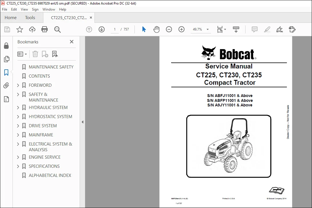
Bobcat CT225, CT230, CT235 Compact Tractor Service Manual 6987029(1-14) – PDF DOWNLOAD
S/N ABFJ11001 & Above
S/N ABFP11001 & Above
S/N A9JY11001 & Above
Description
Bobcat CT225, CT230, CT235 Compact Tractor Service Manual 6987029(1-14) – PDF DOWNLOAD
FILE DETAILS:
Bobcat CT225, CT230, CT235 Compact Tractor Service Manual 6987029(1-14) – PDF DOWNLOAD
Language : English
Pages : 757
Downloadable : Yes
File Type : PDF
Size:21.0 MB
DESCRIPTION:
Bobcat CT225 CT230 CT235 Compact Tractor Service Manual 6987029(1-14) – PDF DOWNLOAD
FOREWORD
This manual is for the Bobcat compact tractor mechanic. It provides necessary servicing and adjustment procedures for the Bobcat compact tractor and its component parts and systems. Refer to the Operation & Maintenance Manual for operating instructions, starting procedure, daily checks, etc.
SAFETY INSTRUCTIONS:
Instructions are necessary before operating or servicing machine. Read Operation & Maintenance Manual,
Handbook and signs (decals) on machine. Follow warnings and instructions in the manuals when making
repairs, adjustments or servicing. Check for correct function after adjustments, repairs or service. Failure
to follow instructions can cause injury or death.
The following publications provide information on the safe use and maintenance of the loader and attachments:
• The Delivery Report is used to assure that complete instructions have been given to the new owner and that the machine
is in safe operating condition.
• The Operation & Maintenance Manual delivered with the loader gives operating information as well as routin e
maintenance and service procedures. It is a part of the loader and must stay with the machine when it is sold. Replacement
Operation & Maintenance Manuals can be ordered from your Bobcat loader dealer.
• The loader has machine signs (decals) which instruct on the safe operation and care. The signs and their locations are
shown in the Operation & Maintenance Manual. Replacement signs are available from your Bobcat loader dealer.
• The loader has a plastic Operator’s Handbook fastened to the operator cab. Its brief instructions are convenient to the
operator. The Handbook is available from your dealer in an English edition or one of many other languages. See your
Bobcat dealer for more information on translated versions.
• The EMI Safety Manual (available in Spanish) delivered with the loader gives general safety information.
• The Service Manual and Parts Manual are available from your dealer for use by mechanics to do shop–type service and
repair work.
• The Skid–Steer Loader Operator Training Course is available through your local dealer. This course is intended to provide
rules and practices for correct operation of the Bobcat loader. The course is available in English and Spanish version.
• The Bobcat Skid–Steer Loader Safety Video is available from your Bobcat Dealer.
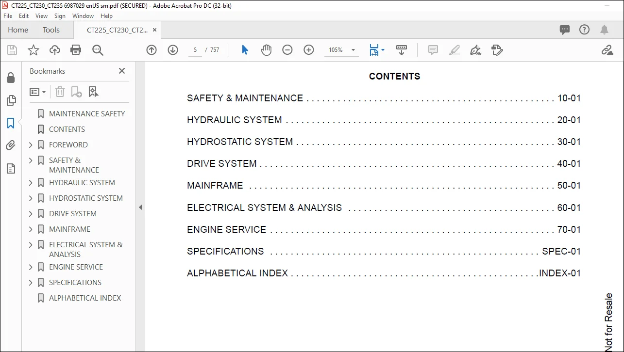
TABLE OF CONTENTS:
Bobcat CT225 CT230 CT235 Compact Tractor Service Manual 6987029(1-14) – PDF DOWNLOAD
MAINTENANCE SAFETY 3
CONTENTS 5
FOREWORD 7
FOREWORD 9
SAFETY INSTRUCTIONS 11
Use Safety Rules 12
Safety Rules For Power Take-Off (PTO) Driven Implements 13
Compact Tractor Requirements and Capabilities 13
FIRE PREVENTION 14
Maintenance 14
Operation 14
Electrical 14
Hydraulic System 14
Fueling 14
Starting 14
Spark Arrester Exhaust System 14
Welding And Grinding 15
Fire Extinguishers 15
SERIAL NUMBER LOCATIONS 16
Compact Tractor Serial Number 16
Engine Serial Number 16
Loader Serial Number (Optional) 16
DELIVERY REPORT 18
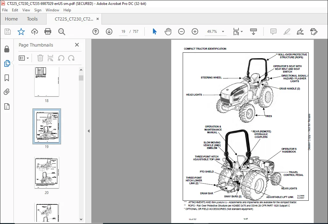
COMPACT TRACTOR IDENTIFICATION 19
COMPACT TRACTOR IDENTIFICATION (WITH OPTIONAL LOADER AND REAR BALLAST) 20
COMPACT TRACTOR IDENTIFICATION (WITH OPTIONAL THREE-POINT IMPLEMENT AND FRONT BALLAST) 21
SAFETY & MAINTENANCE 23
SUPPORTING THE COMPACT TRACTOR ON JACKSTANDS 27
Procedure 27
ENGINE COVER 29
Opening And Closing 29
SEAT BELT 31
Inspection And Maintenance 31
TRANSPORTING THE COMPACT TRACTOR ON A TRAILER 33
Loading And Unloading 33
Fastening 34
TOWING THE COMPACT TRACTOR 35
Procedure 35
AXLE TOE IN 37
Inspection And Maintenance 37
SERVICE SCHEDULE 39
Chart 39
AIR CLEANER SERVICE 41
Replacing Filter Element 41
ENGINE COOLING SYSTEM 43
Checking Level 43
Cleaning 44
Hoses And Clamps 45
Removing And Replacing Coolant 45
FUEL SYSTEM 47
Fuel Specifications 47
Biodiesel Blend Fuel 47
Filling The Fuel Tank 48
Fuel Filter 49
Removing Air From The Fuel System 50
Filling A Portable Fuel Container 50
ENGINE LUBRICATION SYSTEM 51
Checking And Adding Engine Oil 51
Engine Oil Chart 51
Removing And Replacing Oil And Filter 52
HYDRAULIC / HYDROSTATIC / TRANSMISSION SYSTEM 55
Checking And Adding Fluid 55
Transmission / Differential Fluid Chart 55
Removing And Replacing Hydraulic / Hydrostatic / Transmission Filters 56
Removing And Replacing Hydraulic / Transmission Fluid 57
Hoses And Clamps 57
FRONT AXLE 59
Checking And Adding Lubricant 59
Removing And Replacing Lubricant 60
Axle Pivot 60
SPARK ARRESTER MUFFLER 61
Cleaning Procedure 61
COMPACT TRACTOR STORAGE AND RETURN TO SERVICE 63
Storage 63
Return To Service 64
ALTERNATOR BELT 65
Belt Adjustment 65
Belt Replacement 65
LUBRICATING THE COMPACT TRACTOR 67
Lubrication Locations 67
TIRE MAINTENANCE 71
Front Wheel Nuts / Bolts 71
Rear Wheel Nuts 71
Mounting 71
PIVOT PINS 73
Inspection And Maintenance 73
SAFETY INTERLOCK SYSTEM (NEUTRAL START) 75
Inspection And Maintenance 75
SAFETY INTERLOCK SYSTEM (OPERATING) 77
Inspection And Maintenance 77
PARKING BRAKE SYSTEM 79
Inspection And Maintenance 79
BRAKE SYSTEM 81
Inspection And Maintenance 81
Adjusting 82
TRAVEL CONTROL PEDAL 83
Inspection And Maintenance 83
Adjustment Procedure 83
CRUISE CONTROL 85
Inspection And Maintenance 85
Adjusting The Cruise Control Tension 85
CLUTCH SYSTEM 87
Inspection And Maintenance 87
Adjusting 87
Draining Water From Clutch Housing 88
BOB-TACH (HAND LEVER) 89
Inspection And Maintenance 89
HYDRAULIC SYSTEM 91
HYDRAULIC/HYDROSTATIC SCHEMATICS 95
HYDRAULIC SYSTEM INFORMATION 97
Glossary Of Hydraulic / Hydrostatic Symbols For Compact Tractors 97
Troubleshooting The Hydraulic Circuit 101
Troubleshooting The Joystick Valve Circuit 101
Troubleshooting The Power Lift Circuit 102
Troubleshooting The Steering Circuit 103
MAIN RELIEF VALVE 105
Testing Information 105
Testing And Adjusting The Main Relief Valve 105
HYDRAULIC PUMP 111
Removal And Installation 111
Parts Identification 114
Disassembly 115
Assembly 119
STEERING VALVE 123
Removal And Installation 123
Parts Identification 124
Disassembly 125
Inspection 130
Assembly 130
STEERING CYLINDER 137
Removal And Installation 137
Parts Identification 139
Disassembly And Assembly 140
RIGHT JOYSTICK (IF EQUIPPED) 141
Removal And Installation 141
Parts Identification 144
Disassembly And Assembly 145
Adjustment 147
RIGHT JOYSTICK VALVE (IF EQUIPPED) 149
Removal And Installation 149
Parts Identification 152
Disassembly 153
Inspection 157
Assembly 157
HYDRAULIC FILTER 161
Description 161
Filter Bracket Removal And Installation 161
OIL COOLER 163
Removal And Installation 163
THREE POINT HITCH HOUSING 165
Removal And Installation 165
AUXILIARY CONTROL VALVE 167
Inlet Valve Section Disassembly And Assembly 167
No 1 Valve Section Parts Identification 170
No 1 Valve Section Disassembly And Assembly 171
No 2 Valve Section Parts Identification 177
No 2 Valve Section Disassembly And Assembly 178
ROCK SHAFT 185
Removal And Installation 185
Inspection 187
MLS VALVE 189
Removal And Installation 189
Parts Identification 190
Disassembly And Assembly 191
Adjustment 200
THREE POINT CYLINDER 203
Disassembly And Assembly 203
Inspection 206
THREE POINT CYLINDER CONTROL 209
Disassembly And Assembly 209
CYLINDER (Lift) (EARLY MODELS) 215
Testing 215
Removal And Installation 215
Parts Identification 218
Disassembly 219
Assembly 221
CYLINDER (LIFT) (LATE MODELS) 225
Testing 225
Removal And Installation 225
Parts Identification 228
Disassembly 229
Assembly 231
CYLINDER (TILT) (EARLY MODELS) 235
Testing 235
Removal And Installation 235
Parts Identification 237
Disassembly 238
Assembly 240
CYLINDER (TILT) (LATE MODELS) 245
Testing 245
Removal And Installation 245
Parts Identification 247
Disassembly 248
Assembly 250
HYDROSTATIC SYSTEM 253
HYDROSTATIC SYSTEM INFORMATION 255
Troubleshooting Chart 255
HYDROSTATIC PUMP (CT225 AND CT230) 257
Removal And Installation 257
Parts Identification 258
Disassembly 259
Inspection 271
Assembly 273
Hydrostatic Pump Start-Up 284
HYDROSTATIC PUMP (CT235) 285
Removal And Installation 285
Parts Identification 286
Disassembly 287
Inspection 299
Assembly 301
Hydrostatic Pump Start-Up 313
HYDROSTATIC PUMP TESTING 315
Charge Pressure Testing 315
Drive Relief Information 316
Forward Drive Relief Testing 317
Reverse Drive Relief Testing 318
TRAVEL PEDAL 319
Removal And Installation 319
DRIVE SYSTEM 321
SERVICE BRAKE 325
Troubleshooting Chart 325
Description 326
Brake Pedal Clearance Adjustment 326
Stop Switch Gap Adjustment 327
BRAKE PEDAL ASSEMBLY 329
Removal And Installation 329
DRIVESHAFT 333
Removal And Installation 333
AXLE CASE 335
Removal And Installation 335
Parts Identification 337
Disassembly And Assembly 338
BRAKE CASE 343
Removal And Installation 343
Parts Identification 345
Disassembly And Assembly 346
Inspection 349
TRANSMISSION 351
Troubleshooting Chart 351
Middle Case / Output Shaft Group Parts Identification 352
Middle Case / Output Shaft Group Disassembly 353
Middle Case / Output Shaft Group Inspection 357
Range Shifter Shaft Group Parts Identification 358
Range Shifter Shaft Group Disassembly 359
Range Shifter Shaft Group Inspection 367
Rear PTO Group Parts Identification 368
Rear PTO Group Disassembly 369
Rear PTO Group Inspection 375
Differential Parts Identification 376
Differential Disassembly 377
Differential Inspection 384
Pinion Shaft Parts Identification 385
Pinion Shaft Disassembly 386
Pinion Shaft Inspection 387
Front Wheel Driveshaft Parts Identification 388
Front Wheel Driveshaft Disassembly 389
Front Wheel Driveshaft Inspection 392
Mid PTO Shaft Parts Identification 393
Mid PTO Shaft Disassembly 394
Mid PTO Shaft Inspection 396
Mid PTO Shaft Assembly 397
Front Wheel Driveshaft Assembly 399
Pinion Shaft Assembly 402
Differential Assembly 404
Rear PTO Group Assembly 412
Range Shifter Shaft Group Assembly 419
Middle Case / Output Shaft Group Assembly 428
FRONT AXLE 433
Removal And Installation 433
AXLE AND DIFFERENTIAL 435
Troubleshooting Chart 435
Gear Case Cover Parts Identification 436
Gear Case Cover Disassembly 437
Gear Case Cover Inspection 440
Axle Case Group Parts Identification 441
Axle Case Group Disassembly 442
Axle Case Group Inspection 448
Axle Support Removal 449
Pinion Shaft Removal 451
Pinion Shaft Parts Identification 452
Pinion Shaft Disassembly 453
Pinion Shaft Inspection 453
Differential Removal 454
Differential Parts Identification 455
Differential Disassembly 456
Differential Inspection 459
Differential Assembly 460
Differential Installation 464
Pinion Shaft Assembly 465
Pinion Shaft Installation 466
Axle Support Installation 468
Axle Case Group Assembly 470
STEERING AXLE ADJUSTMENT 481
Toe-In Checking 481
Toe-In Adjustment 481
Rocking Force 481
Steering Angle Adjustment 482
SEPARATING THE TRACTOR 483
Procedure 483
MAINFRAME 491
OPERATOR SEAT 493
Removal And Installation 493
CONSOLE COVER 495
Left Side Removal And Installation 495
Right Side Removal And Installation 496
HYDROSTATIC TRANSMISSION CASE 497
Removal And Installation 497
REAR PTO CONTROL 499
Linkage Removal And Installation 499
Disassembly And Assembly 499
MID PTO CONTROL 501
Linkage Removal And Installation 501
Linkage Disassembly And Assembly 501
SPLASH BOARD 503
Removal And Installation 503
FLOOR MAT 505
Removal And Installation 505
FLOOR PLATE 507
Removal And Installation (Left Side) 507
Removal And Installation (Right Side) 509
ENGINE COVER 511
Gas Cylinder Removal And Installation 511
Removal And Installation 511
ENGINE SIDE COVER 513
Removal And Installation 513
FENDER ASSEMBLY 515
Removal And Installation 515
FENDER 519
Removal And Installation 519
FIREWALL 521
Removal And Installation 521
ROPS 523
Removal And Installation 523
PTO SAFETY SHIELD 525
Removal And Installation 525
DRAW BAR 527
Removal And Installation 527
DRAW BAR ASSEMBLY 529
Removal And Installation 529
THREE POINT HITCH LOWER LINKS 531
Left Side Removal And Installation 531
Right Side Removal And Installation 533
Top Link Assembly Removal And Installation 534
FUEL TANK 535
Removal And Installation 535
BOB-TACH (HAND LEVER) 537
Description 537
Removal And Installation 537
Parts Identification 538
Lever And Wedge Disassembly And Assembly 539
ELECTRICAL SYSTEM & ANALYSIS 541
ELECTRICAL SCHEMATIC 543
ELECTRICAL SYSTEM INFORMATION 544
Glossary Of Electrical Symbols 544
Electrical Component Location 547
Troubleshooting 548
Description 549
Fuse And Relay Location – Engine Compartment 549
Fuse And Relay Location – Instrument Panel 550
BATTERY 552
Removing And Installing Battery 552
Battery Maintenance 553
Using A Booster Battery (Jump Starting) 554
ALTERNATOR 556
Belt Adjustment 556
Belt Replacement 556
Charging System Inspection 557
Alternator Voltage Testing 558
Low Voltage Testing 558
High Voltage Testing 559
Removal And Installation 560
Parts Identification 561
STARTER 562
Testing 562
Removal And Installation 563
Parts Identification 564
HOOD LIGHTS 566
Removal And Installation 566
Bulb Removal And Installation 566
REAR LIGHTS 568
Removal And Installation 568
Bulb Removal And Installation 569
SEAT SENSOR 570
Removal And Installation 570
FUEL LEVEL SENDER 572
Removal And Installation 572
INSTRUMENT PANEL 574
Removal And Installation 574
PTO SWITCHES 576
Removal And Installation 576
Adjustment 576
HORN 578
Removal And Installation 578
ENGINE SERVICE 580
ENGINE INFORMATION (CT225, ENGINE MODEL 3A139lWBC) 584
Description 584
Specifications 585
Troubleshooting 593
Engine Removal And Installation 596
Compression – Checking 602
ENGINE INFORMATION (CT230, ENGINE MODEL 3A150lWBC) 604
Description 604
Specifications 605
ENGINE INFORMATION (CT235, ENGINE MODEL 3A165lWh) 614
Description 614
Specifications 615
ENGINE SPEED CONTROL 624
Cable Removal And Installation 624
Lever Removal And Installation 626
SPARK ARRESTER MUFFLER 628
Removal And Installation 628
AIR CLEANER (CT225 AND CT230) 630
Removal And Installation 630
Bracket Removal And Installation 630
AIR CLEANER (CT235) 632
Removal And Installation 632
ENGINE COOLING SYSTEM (CT225 AND CT230) 634
Description 634
Radiator Removal And Installation 635
Water Pump Removal And Installation 639
Water Pump Disassembly And Assembly 639
Thermostat Housing Removal And Installation 640
Testing The Thermostat 640
ENGINE COOLING SYSTEM (CT235) 642
Radiator Removal And Installation 642
LUBRICATION SYSTEM 646
Description 646
Oil Pan Removal And Installation 647
Oil Pump Removal And Installation 647
Oil Pump Inspection 648
Engine Oil Pressure – Testing 649
Oil Filter 649
FUEL SYSTEM 650
Description 650
Fuel Camshaft Removal And Installation 651
Fuel Shutoff Solenoid Checking 651
Fuel Shutoff Solenoid Removal And Installation 652
Fuel Injection Pump Removal And Installation (CT225 And CT230) 652
Fuel Injection Pump Removal And Installation (CT235) 657
Fuel Injection Pump Timing (All Models) 661
Fuel Injector Removal And Installation (CT225 And CT230) 665
Fuel Injector Removal And Installation (CT235) 666
Fuel Injector Nozzle Pressure – Checking 668
Nozzle Spray Condition 669
Valve Seat Tightness 670
Bleeding The Fuel System 670
CYLINDER HEAD 672
Glow Plug – Testing (CT225) 672
Glow Plug – Testing (CT230 And CT235) 672
Glow Plug Removal And Installation (CT225) 673
Glow Plug Removal And Installation (CT230 And CT235) 674
Valve Clearance Adjustment 675
Valve Timing – Checking 675
Cylinder Head Removal And Installation 676
Cylinder Head Bolt Tightening Procedure 679
Cylinder Head Disassembly And Assembly 680
Cylinder Head Servicing 680
Cylinder Head Top Clearance 681
Valve Guide – Checking 681
Reconditioning The Valve And Valve Seat 683
Valve Spring 684
Valve Tappets 685
Rocker Arm And Shaft – Checking 685
CRANKSHAFT AND PISTONS 686
Piston And Connecting Rod Removal And Installation 686
Piston And Connecting Rod – Servicing 688
Cylinder Bore – Checking 691
Connecting Rod – Alignment 691
Crankshaft And Bearings Removal And Installation 692
Crankshaft And Bearings – Servicing 694
CAMSHAFT AND TIMING GEARS 698
Timing Gearcase Cover Removal And Installation 698
Timing Gears Backlash – Checking 700
Idler Gear And Shaft Removal And Installation 701
Camshaft – Servicing 703
Idler Gear And Shaft – Servicing 704
FLYWHEEL AND HOUSING 706
Flywheel Removal And Installation 706
Flywheel Housing Removal And Installation 706
FAN 708
Removal And Installation 708
CLUTCH ASSEMBLY 710
Removal And Installation 710
Clutch Disc Inspection 710
Pressure Plate Inspection 711
Clutch Pedal Play Adjustment 711
Clutch Pedal Stop bolt Adjustment 711
CLUTCH HOUSING 712
Removal And Installation 712
Parts Identification 716
Disassembly 717
Inspection 721
Assembly 723
SPECIFICATIONS 728
CT225 SPECIFICATIONS 730
Machine Dimensions (Standard Machine) 730
Dimensions (With Optional Loader) 731
Performance 732
Controls 732
Engine 733
Hydraulic System 733
Electrical 733
Power Take-Off (PTO) System (Rear-PTO) 734
Power Take-Off (PTO) System (Mid-PTO Optional) 734
Drive System 734
Steering 734
Capacities 735
Tires 735
Loader (If Equipped) 735
CT230 SPECIFICATIONS 736
Machine Dimensions (Standard Machine) 736
Dimensions (With Optional Loader) 737
Performance 738
Controls 738
Engine 739
Hydraulic System 739
Electrical 739
Power Take-Off (PTO) System (Rear-PTO) 740
Power Take-Off (PTO) System (Mid-PTO Optional) 740
Drive System 740
Steering 740
Capacities 741
Tires 741
Loader (If Equipped) 741
CT235 SPECIFICATIONS 742
Machine Dimensions (Standard Machine) 742
Dimensions (With Optional Loader) 743
Performance 744
Controls 744
Engine 745
Hydraulic System 745
Electrical 745
Power Take-Off (PTO) System (Rear-PTO) 746
Power Take-Off (PTO) System (Mid-PTO Optional) 746
Drive System 746
Steering 746
Capacities 747
Tires 747
Loader (If Equipped) 747
HYDRAULIC FLUID SPECIFICATIONS 748
Specifications 748
CONVERSIONS 750
Decimal And Millimeter Equivalent Chart 750
U S To Metric Conversion Chart 751
TORQUE SPECIFICATIONS FOR BOLTS 752
Torque For General SAE Bolts 752
Torque For General Metric Bolts 753
FUEL, COOLANT AND LUBRICANTS (ALL MODELS) 754
Chart 754
ALPHABETICAL INDEX 756
IMAGES PREVIEW OF THE MANUAL:
Contact us: [email protected]
https://vimeo.com/840841184?share=copy
PLEASE NOTE:
- This is the same manual used by the dealers to diagnose and troubleshoot your vehicle
- You will be directed to the download page as soon as the purchase is completed. The whole payment and downloading process will take anywhere between 2-5 minutes
- Need any other service / repair / parts manual, please feel free to contact [email protected] . We still have 50,000 manuals unlisted
s.m