Bobcat CT440, CT445, CT450 Compact Tractor Service Manual 6987079(1-14) – PDF DOWNLOAD
$34.95
Bobcat CT440, CT445, CT450 Compact Tractor Service Manual 6987079(1-14) – PDF DOWNLOAD
HST – S/N ABHE11001 & Above
HST – S/N ABHL11001 & Above
HST – S/N ABHM11001 & Above
SST – S/N AKB911001 & Above
SST – S/N AKBP11001 & Above
Description
Bobcat CT440, CT445, CT450 Compact Tractor Service Manual 6987079(1-14) – PDF DOWNLOAD
FILE DETAILS:
Bobcat CT440, CT445, CT450 Compact Tractor Service Manual 6987079(1-14) – PDF DOWNLOAD
Language : English
Pages :1293
Downloadable : Yes
File Type : PDF
Size:34.8 MB
DESCRIPTION:
Bobcat CT440, CT445, CT450 Compact Tractor Service Manual 6987079(1-14) – PDF DOWNLOAD
FOREWORD
This manual is for the Bobcat compact tractor mechanic. It provides necessary servicing and adjustment procedures for the Bobcat compact tractor and its component parts and systems. Refer to the Operation & Maintenance Manual for operating instructions, starting procedure, daily checks, etc.
Instructions are necessary before operating or servicing machine. Read Operation & Maintenance Manual,
Handbook and signs (decals) on machine. Follow warnings and instructions in the manuals when making
repairs, adjustments or servicing. Check for correct function after adjustments, repairs or service. Failure
to follow instructions can cause injury or death.
The following publications provide information on the safe use and maintenance of the loader and attachments:
• The Delivery Report is used to assure that complete instructions have been given to the new owner and that the machine
is in safe operating condition.
• The Operation & Maintenance Manual delivered with the loader gives operating information as well as routin e
maintenance and service procedures. It is a part of the loader and must stay with the machine when it is sold. Replacement
Operation & Maintenance Manuals can be ordered from your Bobcat loader dealer.
• The loader has machine signs (decals) which instruct on the safe operation and care. The signs and their locations are
shown in the Operation & Maintenance Manual. Replacement signs are available from your Bobcat loader dealer.
• The loader has a plastic Operator’s Handbook fastened to the operator cab. Its brief instructions are convenient to the
operator. The Handbook is available from your dealer in an English edition or one of many other languages. See your
Bobcat dealer for more information on translated versions.
• The EMI Safety Manual (available in Spanish) delivered with the loader gives general safety information.
• The Service Manual and Parts Manual are available from your dealer for use by mechanics to do shop–type service and
repair work.
• The Skid–Steer Loader Operator Training Course is available through your local dealer. This course is intended to provide
rules and practices for correct operation of the Bobcat loader. The course is available in English and Spanish version.
• The Bobcat Skid–Steer Loader Safety Video is available from your Bobcat Dealer.
TABLE OF CONTENTS:
Bobcat CT440, CT445, CT450 Compact Tractor Service Manual 6987079(1-14) – PDF DOWNLOAD
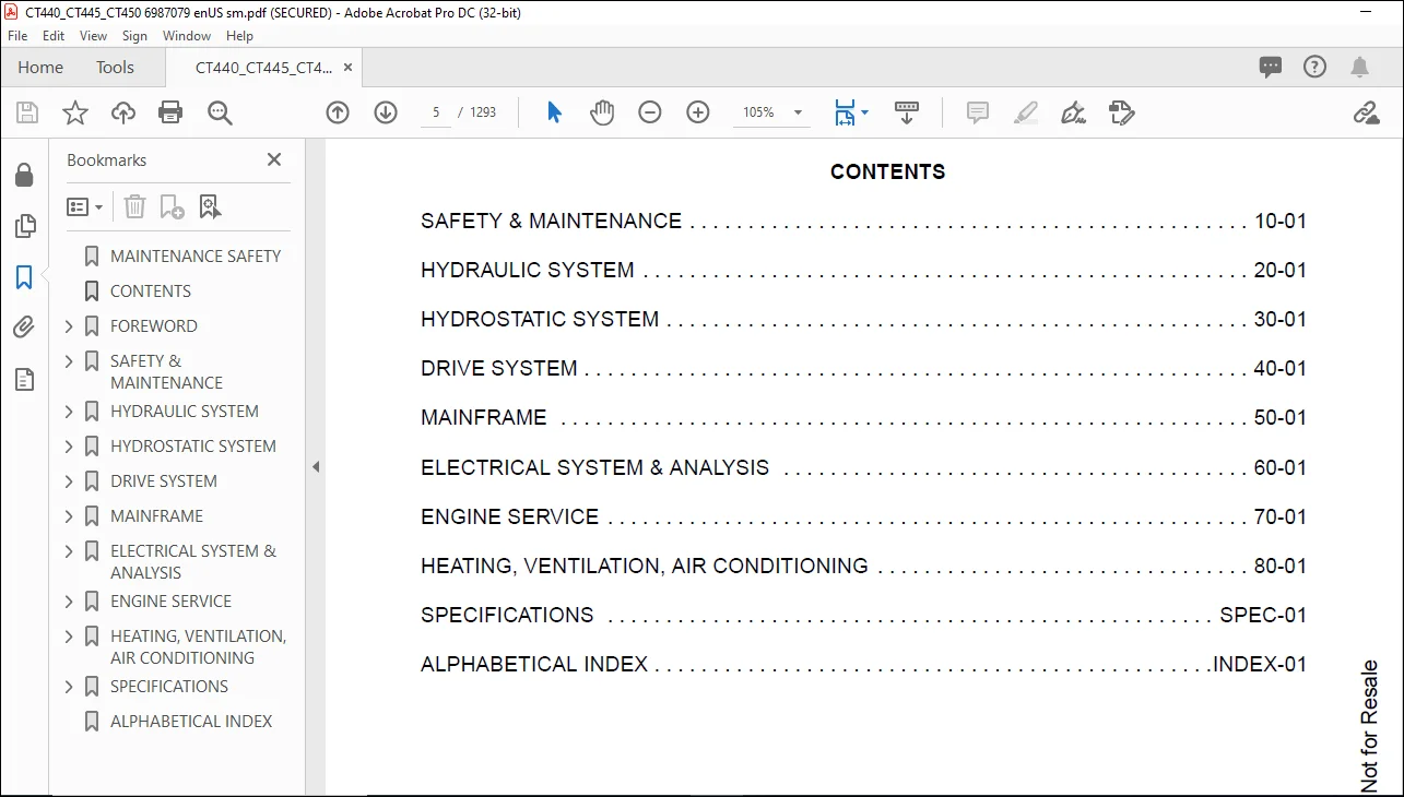
MAINTENANCE SAFETY 3
CONTENTS 5
FOREWORD 7
FOREWORD 9
SAFETY INSTRUCTIONS 11
Use Safety Rules 12
Safety Rules For Power Take-Off (PTO) Driven Implements 13
Compact Tractor Requirements and Capabilities 13
FIRE PREVENTION 14
Maintenance 14
Operation 14
Electrical 14
Hydraulic System 14
Fueling 14
Starting 14
Spark Arrester Exhaust System 14
Welding And Grinding 15
Fire Extinguishers 15
SERIAL NUMBER LOCATIONS 16
Compact Tractor Serial Number 16
Engine Serial Number 16
Loader Serial Number (Optional) 16
DELIVERY REPORT 18
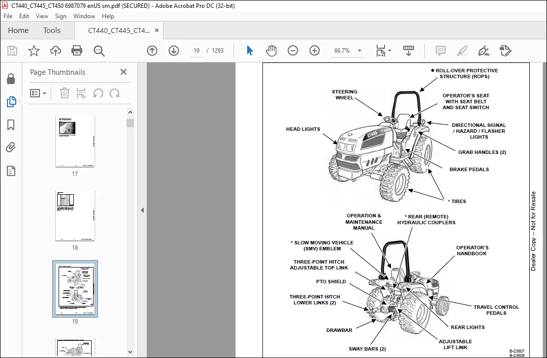
COMPACT TRACTOR IDENTIFICATION 19
COMPACT TRACTOR IDENTIFICATION (WITH OPTIONAL LOADER AND REAR BALLAST) 20
COMPACT TRACTOR IDENTIFICATION (WITH OPTIONAL THREE-POINT IMPLEMENT AND FRONT BALLAST) 21
COMPACT TRACTOR IDENTIFICATION (WITH OPTIONAL CAB) 22
SAFETY & MAINTENANCE 23
SUPPORTING THE COMPACT TRACTOR ON JACKSTANDS 27
Procedure 27
ENGINE COVER 29
Opening And Closing 29
SEAT BELT 31
Inspection And Maintenance 31
TRANSPORTING THE COMPACT TRACTOR ON A TRAILER 33
Loading And Unloading 33
Fastening 34
TOWING THE COMPACT TRACTOR 37
Procedure 37
AXLE TOE IN (HST MODELS) 39
Inspection And Maintenance 39
AXLE TOE IN (SST MODELS) 41
Adjustment 41
SERVICE SCHEDULE 43
Chart 43
AIR CLEANER SERVICE 45
Replacing Filter Element 45
FRESH AIR FILTERS (WITH CAB) 47
Removal And Installation 47
ENGINE COOLING SYSTEM 49
Checking Level 49
Cleaning 50
Hoses And Clamps 50
Removing And Replacing Coolant 51
FUEL SYSTEM 53
Fuel Specifications 53
Biodiesel Blend Fuel 53
Filling The Fuel Tank 54
Fuel Filter 55
Removing Air From The Fuel System 56
Filling A Portable Fuel Container 56
ENGINE LUBRICATION SYSTEM 57
Checking And Adding Engine Oil 57
Engine Oil Chart 57
Removing And Replacing Oil And Filter 58
HYDRAULIC / HYDROSTATIC / TRANSMISSION SYSTEM 61
Checking And Adding Fluid 61
Transmission / Differential Fluid Chart 61
Removing And Replacing Hydraulic / Hydrostatic / Transmission Filters 62
Removing And Replacing Hydraulic / Transmission Fluid 63
Hoses And Clamps 63
FRONT AXLE 65
Checking And Adding Lubricant 65
Removing And Replacing Lubricant 66
Axle Pivot 66
SPARK ARRESTER MUFFLER 67
Cleaning Procedure 67
COMPACT TRACTOR STORAGE AND RETURN TO SERVICE 69
Storage 69
Return To Service 69
ALTERNATOR BELT 71
Belt Adjustment 71
Belt Replacement 71
AIR CONDITIONING BELT 73
Belt Adjustment 73
Belt Replacement 73
LUBRICATING THE COMPACT TRACTOR 75
Lubrication Locations 75
TIRE MAINTENANCE 79
Front Wheel Nuts / Bolts 79
Rear Wheel Nuts / Bolts 79
Mounting 79
Wheel Spacing (AG And Industrial Tires Only) 80
PIVOT PINS 81
Inspection And Maintenance 81
SAFETY INTERLOCK SYSTEM – NEUTRAL START 83
Inspection And Maintenance (HST) 83
Inspection And Maintenance (SST) 84
SAFETY INTERLOCK SYSTEM – OPERATING 85
Inspection And Maintenance (HST) 85
Inspection And Maintenance (SST) 86
PARKING BRAKE SYSTEM 87
Inspection And Maintenance 87
BRAKE SYSTEM 89
Inspection And Maintenance 89
Adjusting 91
TRAVEL CONTROL PEDAL (HST ONLY) 93
Inspection And Maintenance 93
F-N-R LEVER (SST ONLY) 95
Inspection And Maintenance 95
CRUISE CONTROl (HST ONLY) 97
Inspection And Maintenance 97
CLUTCH PEDAL (SST ONLY) 99
Inspection And Maintenance 99
SPEED RANGE LEVER (HST ONLY) 101
Calibration 101
BOB-TACH (HAND LEVER) 103
Inspection And Maintenance 103
CLUTCH PEDAL AND HOUSING (SST ONLY) 105
Draining Water 105
Storage Position 105
DIFFERENTIAL LOCK 107
Inspection And Maintenance 107
Adjustment 107
HYDRAULIC SYSTEM 109
HYDRAULIC/HYDROSTATIC SCHEMATICS 113
HYDRAULIC SYSTEM INFORMATION 117
Glossary Of Hydraulic / Hydrostatic Symbols For Compact Tractors 117
Troubleshooting The Hydraulic Circuit 121
Troubleshooting The Joystick Valve Circuit 121
Troubleshooting The Power Lift Circuit 122
Troubleshooting The Steering Circuit 123
MAIN RELIEF VALVE 125
Testing Information 125
Testing And Adjusting The Main Relief Valve 125
HYDRAULIC PUMP 131
Removal And Installation 131
Parts Identification 133
Disassembly 134
Assembly 138
STEERING VALVE 143
Removal And Installation 143
Parts Identification 144
Disassembly 145
Inspection 150
Assembly 150
STEERING VALVE TESTING 157
Relief Pressure 157
Working Pressure 158
STEERING CYLINDER 159
Removal And Installation 159
Parts Identification 161
Disassembly And Assembly 162
STEERING CYLINDER (SST MODELS) 163
Removal And Installation 163
Parts Identification 166
Disassembly 167
Assembly 169
RIGHT JOYSTICK (WITHOUT CAB) 175
Removal And Installation 175
Parts Identification 177
Disassembly And Assembly 178
Adjustment 180
RIGHT JOYSTICK (WITH CAB) 183
Removal And Installation 183
Parts Identification 185
Disassembly And Assembly 186
Adjustment 188
RIGHT JOYSTICK VALVE (IF EQUIPPED) 189
Removal And Installation 189
Parts Identification 192
Disassembly 193
Inspection 197
Assembly 197
REAR PTO 201
Engagement Testing 201
Adjustment 201
OIL COOLER (HST MODELS) 203
Removal And Installation 203
THREE POINT HITCH HOUSING 205
Removal And Installation 205
AUXILIARY CONTROL VALVE 209
End Cap Section Disassembly And Assembly 209
Valve Section Parts Identification 211
Valve Section Disassembly And Assembly 212
Detent Assembly 216
ROCK SHAFT 219
Removal And Installation 219
MLS VALVE 221
Removal And Installation 221
Parts Identification 222
Disassembly And Assembly 223
Adjustment (HST Models) 232
Adjustment (SST Models) 234
THREE POINT CYLINDER 237
Disassembly And Assembly 237
Inspection 240
THREE POINT CYLINDER CONTROL 243
Disassembly And Assembly 243
Adjusting The Position Control Lever (HST Models) 249
Adjusting The Position Control Lever (SST Models) 251
MODULATOR VALVE 253
Removal And Installation 253
Parts Identification 255
Disassembly And Assembly 256
FRONT WHEEL DRIVE 261
Engagement Testing 261
Adjustment 261
CYLINDER (Lift) (EARLY MODELS) 263
Testing 263
Removal And Installation 263
Parts Identification 266
Disassembly 267
Assembly 269
CYLINDER (LIFT) (LATE MODELS) 273
Testing 273
Removal And Installation 273
Parts Identification 276
Disassembly 277
Assembly 279
CYLINDER (TILT) (EARLY MODELS) 283
Testing 283
Removal And Installation 284
Parts Identification 285
Disassembly 286
Assembly 288
CYLINDER (TILT) (LATE MODELS) 293
Testing 293
Removal And Installation 293
Parts Identification 295
Disassembly 296
Assembly 298
HYDROSTATIC SYSTEM 301
HYDROSTATIC SYSTEM INFORMATION (HST MODELS) 303
Troubleshooting Chart 303
HYDROSTATIC PUMP (HST MODELS) 305
Removal And Installation 305
Parts Identification 311
Disassembly 313
Inspection 330
Assembly 333
Hydrostatic Pump Start-Up 352
HYDROSTATIC PUMP TESTING (HST MODELS) 353
Charge Pressure Testing 353
Hydrostatic Drive Pressure Testing 354
Neutral Valves 356
TRAVEL CONTROL PEDALS (HST MODELS) 357
Removal And Installation 357
TRAVEL CONTROL PEDAL LINKAGE (HST MODELS) 359
Removal And Installation 359
TRAVEL CONTROL PEDAL PIVOT ARMS (HST MODELS) 361
Removal And Installation 361
DRIVE SYSTEM 363
SERVICE BRAKE 369
Troubleshooting Chart 369
Description 369
Inspection And Maintenance 370
Adjusting 372
Stop Switch Adjustment (HST Models) 373
Stop Switch Adjustment (SST Models) 375
BRAKE PEDAL ASSEMBLY 377
Removal And Installation 377
BRAKE / CLUTCH PEDAL ASSEMBLY (SST MODELS) 381
Removal And Installation 381
DRIVESHAFT (EARLY MODELS) 385
Removal And Installation 385
DRIVESHAFT (LATER MODELS) 387
Removal And Installation 387
AXLE CASE 389
Removal And Installation 389
Parts Identification 391
Disassembly And Assembly 392
BRAKE CASE 397
Removal And Installation 397
Parts Identification 399
Disassembly And Assembly 400
Inspection 403
TRANSMISSION (HST MODELS) 405
Troubleshooting Chart 405
Middle Case / PTO Clutch Group Parts Identification 406
Middle Case / PTO Clutch Group Disassembly 407
Middle Case / PTO Clutch Group Inspection 414
Middle Case / PTO Countershaft Group Parts Identification 415
Middle Case / PTO Countershaft Group Disassembly 416
Middle Case / PTO Countershaft Group Inspection 417
Middle Case / 23 Gear Shaft Group Parts Identification 418
Middle Case / 23 Gear Shaft Group Disassembly 419
Middle Case / 23 Gear Shaft Group Inspection 419
Middle Case / Countershaft Group Parts Identification 420
Middle Case / Countershaft Group Disassembly 421
Middle Case / Countershaft Group Inspection 422
Bearing Cover / Shift Links Parts Identification 423
Bearing Cover / Shift Links Disassembly 424
Bearing Cover / Shift Links Inspection 428
Pinion Shaft Group Parts Identification 429
Pinion Shaft Group Disassembly 430
Pinion Shaft Group Inspection 436
PTO Shaft Group Parts Identification 437
PTO Shaft Group Disassembly 438
PTO Shaft Group Inspection 441
Range Shifter Shaft Group Parts Identification 442
Range Shifter Shaft Group Disassembly 443
Range Shifter Shaft Group Inspection 444
PTO 15 Gear Shaft Group Parts Identification 445
PTO 15 Gear Shaft Group Disassembly 446
PTO 15 Gear Shaft Group Inspection 448
Idle Shaft Group Parts Identification 449
Idle Shaft Group Disassembly 450
Idle Shaft Group Inspection 454
Front Wheel Drive Shaft Group Parts Identification 455
Front Wheel Drive Shaft Group Disassembly 456
Front Wheel Drive Shaft Group Inspection 458
Rear PTO Shaft Group Parts Identification 459
Rear PTO Shaft Group Disassembly 460
Rear PTO Shaft Group Inspection 462
Differential Parts Identification 463
Differential Disassembly 464
Differential Inspection 471
Differential Assembly 472
Rear PTO Shaft Group Assembly 480
Front Wheel Drive Shaft Group Assembly 482
Idle Shaft Group Assembly 484
PTO 15 Gear Shaft Group Assembly 487
Range Shifter Shaft Group Assembly 490
PTO Shaft Group Assembly 491
Pinion Shaft Group Assembly 494
Bearing Cover / Shift Links Assembly 500
Middle Case / Countershaft Group Assembly 506
Middle Case / 23 Gear Shaft Group Assembly 508
Middle Case / PTO Countershaft Group Assembly 509
Middle Case / PTO Clutch Group Assembly 510
TRANSMISSION (SST MODELS) 517
Troubleshooting Chart 517
Transmission Case Removal 518
Transmission Case Parts Identification 522
Transmission Case Disassembly 523
Bearing Cover / PTO Countershaft Parts Identification 530
Bearing Cover / PTO Countershaft Disassembly 531
Middle Case / 23 Gear Shaft Group Inspection 531
Bearing Cover / PTO Countershaft Inspection 532
Bearing Cover / PTO Driveshaft Parts Identification 533
Bearing Cover / PTO Driveshaft Disassembly 534
Bearing Cover / PTO Driveshaft Inspection 534
Bearing Cover / Shift Links Parts Identification 535
Bearing Cover / Shift Links Disassembly 536
Bearing Cover / Shift Links Inspection 538
Bearing Cover / Countershaft Parts Identification 539
Bearing Cover / Countershaft Disassembly 540
Bearing Cover / Countershaft Inspection 547
Bearing Cover / Main Shaft Parts Identification 548
Bearing Cover / Main Shaft Disassembly 549
Bearing Cover / Main Shaft Inspection 549
Middle Case Removal 550
Middle Case / Bearing Cover Removal 551
Middle Case / Shift Link Parts Identification 552
Middle Case / Shift Link Disassembly 553
Middle Case / Shift Link Inspection 555
Middle Case / 19 Gear Shaft Parts Identification 556
Middle Case / 19 Gear Shift Disassembly 557
Middle Case / 19 Gear Shaft Inspection 557
Middle Case / Shuttle Shaft Parts Identification 558
Middle Case / Shuttle Shaft Disassembly 559
Middle Case / Shuttle Shaft Inspection 566
Middle Case / 23-20 Gear Shaft Parts Identification 567
Middle Case / 23-20 Gear Shaft Disassembly 568
Middle Case / 23-30 Gear Shaft Inspection 568
Middle Case / PTO Clutch Parts Identification 569
Middle Case / PTO Clutch Disassembly 570
Middle Case / PTO Clutch Inspection 574
Middle Case Bearing Cover / Shift Links Parts Identification 575
Middle Case Bearing Cover / Shift Links Disassembly 576
Middle Case Bearing Cover / Shift Links Inspection 580
Pinion Shaft Parts Identification 581
Pinion Shaft Disassembly 582
Pinion Shaft Inspection 588
PTO Shaft Parts Identification 589
PTO Shaft Disassembly 590
PTO Shaft Inspection 593
Range Shifter Shaft Parts Identification 594
Range Shifter Shaft Disassembly 595
Range Shifter Shaft Inspection 596
PTO 15 Gear Shaft Parts Identification 597
PTO 15 Gear Shaft Disassembly 598
PTO 15 Gear Shaft Inspection 600
Idle Shaft Parts Identification 601
Idle Shaft Disassembly 602
Idle Shaft Inspection 606
Front Wheel Drive Shaft Parts Identification 607
Front Wheel Drive Shaft Disassembly 608
Front Wheel Drive Shaft Inspection 610
Rear PTO Shaft Parts Identification 611
Rear PTO Shaft Disassembly 612
Rear PTO Shaft Inspection 614
Differential Parts Identification 615
Differential Disassembly 616
Differential Inspection 623
Differential Assembly 624
Rear PTO Shaft Assembly 632
Front Wheel Drive Shaft Assembly 634
Idle Shaft Assembly 636
PTO 15 Gear Shaft Assembly 639
Range Shifter Shaft Assembly 642
PTO Shaft Assembly 643
Pinion Shaft Assembly 646
Middle Case Bearing Cover / Shift Links Assembly 652
Middle Case / PTO Clutch Assembly 658
Middle Case / 23-20 Gear Shaft Assembly 662
Middle Case / Shuttle Shaft Assembly 663
Middle Case / 19 Gear Shaft Assembly 670
Middle Case / Shift Link Assembly 671
Middle Case / Bearing Cover Installation 674
Middle Case Installation 674
Bearing Cover / Main Shaft Assembly 675
Bearing Cover / Countershaft Assembly 676
Bearing Cover / Shift Links Assembly 684
Bearing Cover / PTO Driveshaft Assembly 689
Bearing Cover / PTO Countershaft Assembly 690
Transmission Case Assembly 691
Transmission Case Installation 699
FRONT AXLE 703
Removal And Installation 703
FRONT AXLE (SST MODELS) 707
Removal And Installation 707
AXLE AND DIFFERENTIAL 711
Troubleshooting Chart 711
Front Axle Cover Parts Identification 712
Front Axle Cover Disassembly 713
Front Axle Cover Inspection 716
Front Axle Case Group Parts Identification 717
Front Axle Case Group Disassembly 718
Bevel Gear Case Group Parts Identification 721
Bevel Gear Case Group Disassembly 722
Bevel Gear Case Group Inspection 724
Axle Shaft Group Parts Identification 725
Axle Shaft Group Disassembly 726
Axle Shaft Group Inspection 727
Axle Support Removal 728
Pinion Shaft Removal 730
Pinion Shaft Parts Identification 731
Pinion Shaft Disassembly 732
Pinion Shaft Inspection 732
Differential Removal 733
Differential Parts Identification 734
Differential Disassembly 735
Differential Inspection 738
Differential Assembly 739
Differential Installation 743
Pinion Shaft Assembly 744
Pinion Shaft Installation 745
Axle Support Installation 747
Axle Shaft Group Assembly 749
Bevel Gear Case Group Assembly 751
Front Axle Case Group Assembly 753
Front Axle Cover Assembly 757
AXLE AND DIFFERENTIAL (SST MODELS) 761
Troubleshooting Chart 761
Front Axle Cover Parts Identification 762
Front Axle Cover Disassembly 763
Front Axle Cover Inspection 766
Front Axle Case Group Parts Identification 767
Front Axle Case Group Disassembly 768
Bevel Gear Case Group Parts Identification 771
Bevel Gear Case Group Disassembly 772
Bevel Gear Case Group Inspection 774
Axle Shaft Group Parts Identification 775
Axle Shaft Group Disassembly 776
Axle Shaft Group Inspection 777
Axle Support Removal 778
Pinion Shaft Removal 780
Pinion Shaft Parts Identification 781
Pinion Shaft Disassembly 782
Pinion Shaft Inspection 782
Differential Removal 783
Differential Parts Identification 784
Differential Disassembly 785
Differential Inspection 788
Differential Assembly 789
Differential Installation 793
Pinion Shaft Assembly 794
Pinion Shaft Installation 795
Axle Support Installation 797
Axle Shaft Group Assembly 799
Bevel Gear Case Group Assembly 801
Front Axle Case Group Assembly 803
Front Axle Cover Assembly 807
STEERING AXLE ADJUSTMENT (HST MODELS) 811
Toe-In Checking 811
Toe-In Adjustment 811
Rocking Force 811
Steering Angle Adjustment 812
STEERING AXLE ADJUSTMENT (SST MODELS) 813
Rocking Force 813
Steering Angle Adjustment 814
Toe-In Checking 814
Toe-In Adjustment 815
SEPARATING THE TRACTOR (HST MODELS) 817
Procedure 817
SEPARATING THE TRACTOR (SST MODELS) 823
Procedure 823
MAINFRAME 829
OPERATOR SEAT 833
Removal And Installation 833
CONSOLE COVER (WITHOUT CAB) 835
Left Side Removal And Installation 835
Right Side Removal And Installation 836
CONSOLE COVER (WITH CAB) 837
Left Side Removal And Installation 837
Right Side Removal And Installation 838
TRANSMISSION CASE (HST MODELS) 841
Removal And Installation 841
TRANSMISSION CASE (SST MODELS) 845
Removal And Installation 845
FUEL TANK 847
Removal And Installation 847
MID PTO CONTROL 851
Lever Removal And Installation 851
SPLASH BOARD 853
Removal And Installation 853
FLOOR MAT (HST MODELS) 855
Removal And Installation 855
FLOOR MAT (SST MODELS) 857
Removal And Installation 857
FLOOR PLATE 859
Removal And Installation 859
ENGINE COVER 861
Gas Cylinder Removal And Installation 861
Removal And Installation 861
GRILLE 863
Removal And Installation 863
ENGINE SIDE COVER 865
Removal And Installation 865
FENDER ASSEMBLY (WITHOUT CAB) (HST MODELS) 867
Removal And Installation 867
Fender Mount Removal And Installation 873
FENDER ASSEMBLY (SST MODELS) 875
Removal And Installation 875
Fender Mount Removal And Installation 881
FENDER (WITHOUT CAB) 883
Removal And Installation 883
FENDER (WITH CAB) 885
Removal And Installation 885
FIREWALL (WITHOUT CAB) (HST MODELS) 887
Removal And Installation 887
FIREWALL (SST MODELS) 891
Removal And Installation 891
FIREWALL (WITH CAB) (HST MODELS) 895
Removal And Installation 895
ROPS 901
Removal And Installation 901
Bracket Removal And Installation 902
PTO SAFETY SHIELD 903
Removal And Installation 903
DRAW BAR 905
Removal And Installation 905
DRAW BAR ASSEMBLY 907
Removal And Installation 907
THREE POINT HITCH LOWER LINKS 909
Left Side Removal And Installation 909
Right Side Removal And Installation 910
Top Link Assembly Removal And Installation 911
FRONT WORK LIGHT MOUNT (WITH CAB) 913
Removal And Installation 913
CAB COVER 915
Removal And Installation 915
CAB POST COVER 917
Removal And Installation 917
INNER FENDER ACCESS COVER (WITH CAB) 921
Removal And Installation 921
CAB (HST MODELS) 923
Removal And Installation 923
Door Removal And Installation 931
Windshield Removal And Installation 932
Front Lower Window Removal And Installation 934
Lower Front Window Removal And Installation 934
Rear Window Removal And Installation 935
Side Window Removal And Installation 936
Door Glass Removal And Installation 936
HEADLINER 939
Removal And Installation 939
BOB-TACH (HAND LEVER) 941
Description 941
Removal And Installation 941
Parts Identification 942
Lever And Wedge Disassembly And Assembly 943
ELECTRICAL SYSTEM & ANALYSIS 945
ELECTRICAL SCHEMATICS 947
ELECTRICAL SYSTEM INFORMATION 950
Glossary Of Electrical Symbols 950
Electrical Component Location (Without Cab) (HST Models) 953
Electrical Component Location (With Cab) (HST Models) 954
Electrical Component Location (SST Models) 955
Troubleshooting 956
ELECTRICAL SYSTEM 957
Description 957
Fuse And Relay Location – Engine Compartment 957
Fuse And Relay Location – Cab (If Equipped) 958
Fuse And Relay Location – Instrument Panel – HST Models 959
Fuse And Relay Location – Instrument Panel – SST Models 960
BATTERY 962
Removing And Installing Battery 962
Battery Maintenance 963
Using A Booster Battery (Jump Starting) 964
ALTERNATOR 966
Belt Adjustment 966
Belt Replacement 966
Charging System Inspection 967
Alternator Voltage Testing 968
Low Voltage Testing 968
High Voltage Testing 969
Removal And Installation 970
Parts Identification 971
STARTER 972
Testing 972
Removal And Installation 973
Parts Identification 974
HOOD LIGHTS 976
Removal And Installation 976
Bulb Removal And Installation 976
REAR LIGHTS 978
Removal And Installation 978
Bulb Removal And Installation 979
FRONT LIGHTS (WITH CAB) 980
Removal And Installation 980
Bulb Removal And Installation 981
SEAT SENSOR 982
Removal And Installation 982
FUEL LEVEL SENDER 984
Removal And Installation 984
INSTRUMENT PANEL 986
Removal And Installation 986
STEERING COLUMN COVER 988
Removal And Installation 988
PTO SWITCH (REAR) 990
Inspection And Maintenance 990
Removal And Installation 990
PTO LEVER (MID) (IF EQUIPPED) 992
Inspection And Maintenance 992
PTO Switch Removal And Installation 993
Adjustment 994
HORN 996
Removal And Installation 996
REAR WORK LIGHT (WITH CAB) 998
Removal And Installation 998
Disassembly And Assembly 998
FRONT WORK LIGHT (WITH CAB) 1000
Removal And Installation 1000
Disassembly And Assembly 1000
CRUISE CONTROL (HST ONLY) 1002
Inspection And Maintenance 1002
Switch Removal And Installation 1003
Magnet Removal And Installation 1003
Controller Removal And Installation 1003
SPEED RANGE LEVER (HST ONLY) 1004
Calibration 1004
Controller Removal And Installation 1005
FORWARD – NEUTRAL – REVERSE (F-N-R) LEVER (SST MODELS) 1006
Removal And Installation 1006
F-N-R Lever Disassembly And Assembly 1007
ENGINE SERVICE 1008
ENGINE INFORMATION (CT440, ENGINE MODEL 4A200LWH) 1012
Description 1012
Specifications 1013
Troubleshooting 1021
Engine Removal And Installation (All Models) 1024
Compression – Checking 1031
ENGINE INFORMATION (CT445, ENGINE MODEL 4A220LWH) 1032
Description 1032
Specifications 1033
Troubleshooting 1041
Engine Removal And Installation (All Models) 1044
Compression – Checking 1051
ENGINE INFORMATION (CT450, ENGINE MODEL 4B243LWH) 1052
Description 1052
Specifications 1053
Engine Bolt Torque 1060
Troubleshooting 1061
Engine Removal And Installation (All Models) 1064
Compression – Checking 1071
ENGINE SPEED CONTROL 1072
Cable Removal And Installation 1072
Lever Removal And Installation 1074
ENGINE SPEED CONTROL PEDAL (SST MODELS) 1076
Removal And Installation 1076
Cable Removal And Installation 1076
SPARK ARRESTER MUFFLER 1078
Removal And Installation 1078
AIR CLEANER 1080
Removal And Installation 1080
ENGINE COOLING SYSTEM 1082
Description 1082
Radiator Removal And Installation 1083
Water Pump Removal And Installation 1087
Water Pump Disassembly And Assembly 1087
Thermostat Housing Removal And Installation 1088
Testing The Thermostat 1088
LUBRICATION SYSTEM 1090
Description 1090
Oil Pan Removal And Installation 1091
Oil Pump Removal And Installation 1091
Oil Pump Inspection 1092
Engine Oil Pressure – Testing 1093
Oil Filter 1093
FUEL SYSTEM 1094
Description 1094
Fuel Camshaft Removal And Installation 1095
Fuel Shutoff Solenoid Checking 1095
Fuel Shutoff Solenoid Removal And Installation 1096
Fuel Injection Pump Removal And Installation 1096
Fuel Injection Pump Timing 1102
Fuel Injector Removal And Installation 1105
Fuel Injector Nozzle Pressure – Checking 1107
Nozzle Spray Condition 1108
Valve Seat Tightness 1109
Bleeding The Fuel System 1110
CYLINDER HEAD 1112
Glow Plug – Testing 1112
Glow Plug Removal And Installation 1113
Valve Clearance Adjustment 1114
Valve Timing – Checking 1114
Cylinder Head Removal And Installation 1115
Cylinder Head Bolt Tightening Procedure 1118
Cylinder Head Disassembly And Assembly 1119
Cylinder Head Servicing 1119
Cylinder Head Top Clearance 1120
Valve Guide – Checking 1120
Reconditioning The Valve And Valve Seat 1122
Valve Spring 1123
Valve Tappets 1124
Rocker Arm And Shaft – Checking 1124
CRANKSHAFT AND PISTONS 1126
Piston And Connecting Rod Removal And Installation 1126
Piston And Connecting Rod – Servicing 1128
Cylinder Bore – Checking 1130
Connecting Rod – Alignment 1130
Crankshaft And Bearings Removal And Installation 1131
Crankshaft And Bearings – Servicing 1133
CAMSHAFT AND TIMING GEARS 1136
Timing Gearcase Cover Removal And Installation 1136
Timing Gears Backlash – Checking 1138
Idler Gear And Shaft Removal And Installation 1139
Camshaft – Servicing 1141
Idler Gear And Shaft – Servicing 1142
FLYWHEEL AND HOUSING (HST MODELS) 1144
Flywheel Removal And Installation 1144
Flywheel Housing Removal And Installation 1145
FLYWHEEL AND HOUSING (SST MODELS) 1146
Flywheel Removal And Installation 1146
Flywheel Housing Removal And Installation 1147
FAN 1148
Removal And Installation 1148
CLUTCH ASSEMBLY (SST MODELS) 1150
Troubleshooting Chart 1150
Removal And Installation 1151
Clutch Disc Inspection 1152
Pressure Plate Inspection 1152
Clutch Pedal Play And Stopper Bolt Adjustment 1152
CLUTCH LEVER (SST MODELS) 1154
Parts Identification 1154
Disassembly 1155
Inspection 1157
Assembly 1158
HEATING, VENTILATION, AIR CONDITIONING 1160
HEATER COIL 1162
Removal And Installation 1162
BLOWER FAN 1164
Removal And Installation 1164
HEATER VALVE 1166
Removal And Installation 1166
AIR CONDITIONING SYSTEM FLOW 1169
Principals 1169
Chart 1170
COMPONENTS 1172
Identification 1172
SAFETY 1176
Safety Equipment 1176
REGULAR MAINTENANCE 1178
Fresh Air Filter 1178
Air Conditioning Belt 1178
Cleaning The Condenser 1178
RESISTOR 1180
Removal And Installation 1180
GENERAL AIR CONDITIONING SERVICE GUIDELINES 1182
Compressor Oil 1182
Compressor Oil Check 1183
Component Replacement And Refrigeration Leaks 1184
SYSTEM TROUBLESHOOTING CHART 1186
Blower Motor Does Not Operate 1186
Gauge Pressure Related Troubleshooting 1187
TEMPERATURE / PRESSURE 1190
Chart 1190
AIR CONDITIONING SERVICE 1192
Chart 1192
SYSTEM CHARGING AND RECLAMATION 1194
Reclamation Procedure 1194
Charging Procedure With A Manifold Gauge Set 1197
COMPRESSOR 1200
Removal And Installation 1200
CONDENSER 1202
Removal And Installation 1202
RECEIVER / DRIER 1206
Removal And Installation 1206
HVAC CONTROL PANEL 1208
Removal And Installation 1208
PRESSURE SWITCH 1210
Removal And Installation 1210
EVAPORATOR / HEATER UNIT 1212
Removal And Installation 1212
EVAPORATOR / HEATER UNIT COVER 1216
Removal And Installation 1216
FRONT AIR DUCT 1218
Removal And Installation 1218
SIDE AIR DUCT 1220
Removal And Installation 1220
THERMOSTAT 1222
Removal And Installation 1222
EXPANSION VALVE 1224
Removal And Installation 1224
EVAPORATOR 1226
Removal And Installation 1226
SPECIFICATIONS 1228
CT440 SPECIFICATIONS (HST) 1232
Compact Tractor Loader Lift Capacities 1232
Ballast (Rear) 1232
Three-Point Hitch Specifications 1233
Towing Weight 1233
Maximum Drawbar Tongue Weight 1233
Ballast (Front) 1233
Dimensions (Standard Machine) 1234
Dimensions (With Optional Loader, S/N AL4F00101 & Above, S/N AKPW00101 & Above) 1235
Dimensions (With Optional Loader, S/N AE3500101 & Above) 1236
Performance 1237
Controls 1237
Engine 1238
Hydraulic System 1238
Electrical 1238
Power Take-Off (PTO) System (Rear-PTO) 1239
Power Take-Off (PTO) System (Mid-PTO Optional) 1239
Drive System 1239
Steering 1239
Capacities 1240
Tires 1240
Loader (If Equipped) 1240
CT445 SPECIFICATIONS (HST) 1242
Compact Tractor Loader Lift Capacities 1242
Ballast (Rear) 1242
Three-Point Hitch Specifications 1243
Towing Weight 1243
Maximum Drawbar Tongue Weight 1243
Ballast (Front) 1243
Dimensions (Standard Machine) 1244
Dimensions (With Optional Loader, S/N AL4F00101 & Above, S/N AKPW00101 & Above) 1245
Dimensions (With Optional Loader, S/N AE3500101 & Above) 1246
Performance 1247
Controls 1247
Engine 1248
Hydraulic System 1248
Electrical 1248
Power Take-Off (PTO) System (Rear-PTO) 1249
Power Take-Off (PTO) System (Mid-PTO Optional) 1249
Drive System 1249
Steering 1250
Capacities 1250
Tires 1250
Loader (If Equipped) 1250
CT445 SPECIFICATIONS (sST) 1252
Compact Tractor Loader Lift Capacities 1252
Ballast (Rear) 1252
Three-Point Hitch Specifications 1253
Towing Weight 1253
Maximum Drawbar Tongue Weight 1253
Ballast (Front) 1253
Dimensions (Standard Machine) 1254
Dimensions (With Optional Loader, S/N AL4F00101 & Above, S/N AKPW00101 & Above) 1255
Dimensions (With Optional Loader, S/N AE3500101 & Above) 1256
Performance 1257
Controls 1257
Engine 1258
Hydraulic System 1258
Electrical 1258
Power Take-Off (PTO) System (Rear-PTO) 1259
Power Take-Off (PTO) System (Mid-PTO Optional) 1259
Drive System 1260
Steering 1261
Capacities 1261
Tires 1261
Loader (If Equipped) 1261
CT450 SPECIFICATIONS (HST) 1262
Compact Tractor Loader Lift Capacities 1262
Ballast (Rear) 1262
Three-Point Hitch Specifications 1263
Towing Weight 1263
Maximum Drawbar Tongue Weight 1263
Ballast (Front) 1263
Dimensions (Standard Machine) 1264
Dimensions (With Optional Loader, S/N AL4F00101 & Above, S/N AKPW00101 & Above) 1265
Dimensions (With Optional Loader, S/N AE3500101 & Above) 1266
Performance 1267
Controls 1267
Engine 1268
Hydraulic System 1268
Electrical 1268
Power Take-Off (PTO) System (Rear-PTO) 1269
Power Take-Off (PTO) System (Mid-PTO Optional) 1269
Drive System 1269
Steering 1270
Capacities 1270
Tires 1270
Loader (If Equipped) 1270
CT450 SPECIFICATIONS (sST) 1272
Compact Tractor Loader Lift Capacities 1272
Ballast (Rear) 1272
Three-Point Hitch Specifications 1273
Towing Weight 1273
Maximum Drawbar Tongue Weight 1273
Ballast (Front) 1273
Dimensions (Standard Machine) 1274
Dimensions (With Optional Loader, S/N AL4F00101 & Above, S/N AKPW00101 & Above) 1275
Dimensions (With Optional Loader, S/N AE3500101 & Above) 1276
Performance 1277
Controls 1277
Engine 1278
Hydraulic System 1278
Electrical 1278
Power Take-Off (PTO) System (Rear-PTO) 1279
Power Take-Off (PTO) System (Mid-PTO Optional) 1279
Drive System 1280
Steering 1281
Capacities 1281
Tires 1281
Loader (If Equipped) 1281
TORQUE SPECIFICATIONS FOR BOLTS 1282
Torque For General SAE Bolts 1282
Torque For General Metric Bolts 1283
HYDRAULIC FLUID SPECIFICATIONS 1284
Specifications 1284
CONVERSIONS 1286
Decimal And Millimeter Equivalent Chart 1286
U S To Metric Conversion Chart 1287
FUEL, COOLANT AND LUBRICANTS (ALL MODELS) 1288
Chart 1288
ALPHABETICAL INDEX 1290
IMAGES PREVIEW OF THE MANUAL:
Questions? Email us: [email protected]
https://vimeo.com/840845772?share=copy
PLEASE NOTE:
- This is the same manual used by the dealers to diagnose and troubleshoot your vehicle
- You will be directed to the download page as soon as the purchase is completed. The whole payment and downloading process will take anywhere between 2-5 minutes
- Need any other service / repair / parts manual, please feel free to contact [email protected] . We still have 50,000 manuals unlisted
s.m


