Bobcat E10 Compact Excavator Service Manual 6986788 (08-20) – PDF DOWNLOAD
$34.95
Bobcat E10 Compact Excavator Service Manual 6986788 (08-20) – PDF DOWNLOAD
S/N A33P11001 & Above
S/N B4PD11001 & Above
S/N B4K911001 & Above
Description
Bobcat E10 Compact Excavator Service Manual 6986788 (08-20) – PDF DOWNLOAD
FILE DETAILS:
Bobcat E10 Compact Excavator Service Manual 6986788 (08-20) – PDF DOWNLOAD
Language : English
Pages : 724
Downloadable : Yes
File Type : PDF
Size: 22.9 MB
DESCRIPTION:
Bobcat E10 Compact Excavator Service Manual 6986788 (08-20) – PDF DOWNLOAD
FOREWORD
This manual is for the Bobcat excavator mechanic. It provides necessary servicing and adjustment
procedures for the Bobcat excavator and its component parts and systems. Refer to the Operation &
Maintenance Manual for operating instructions, starting procedure, daily checks, etc.
The following publications provide information on the safe use and maintenance of the Bobcat machine and attachments:
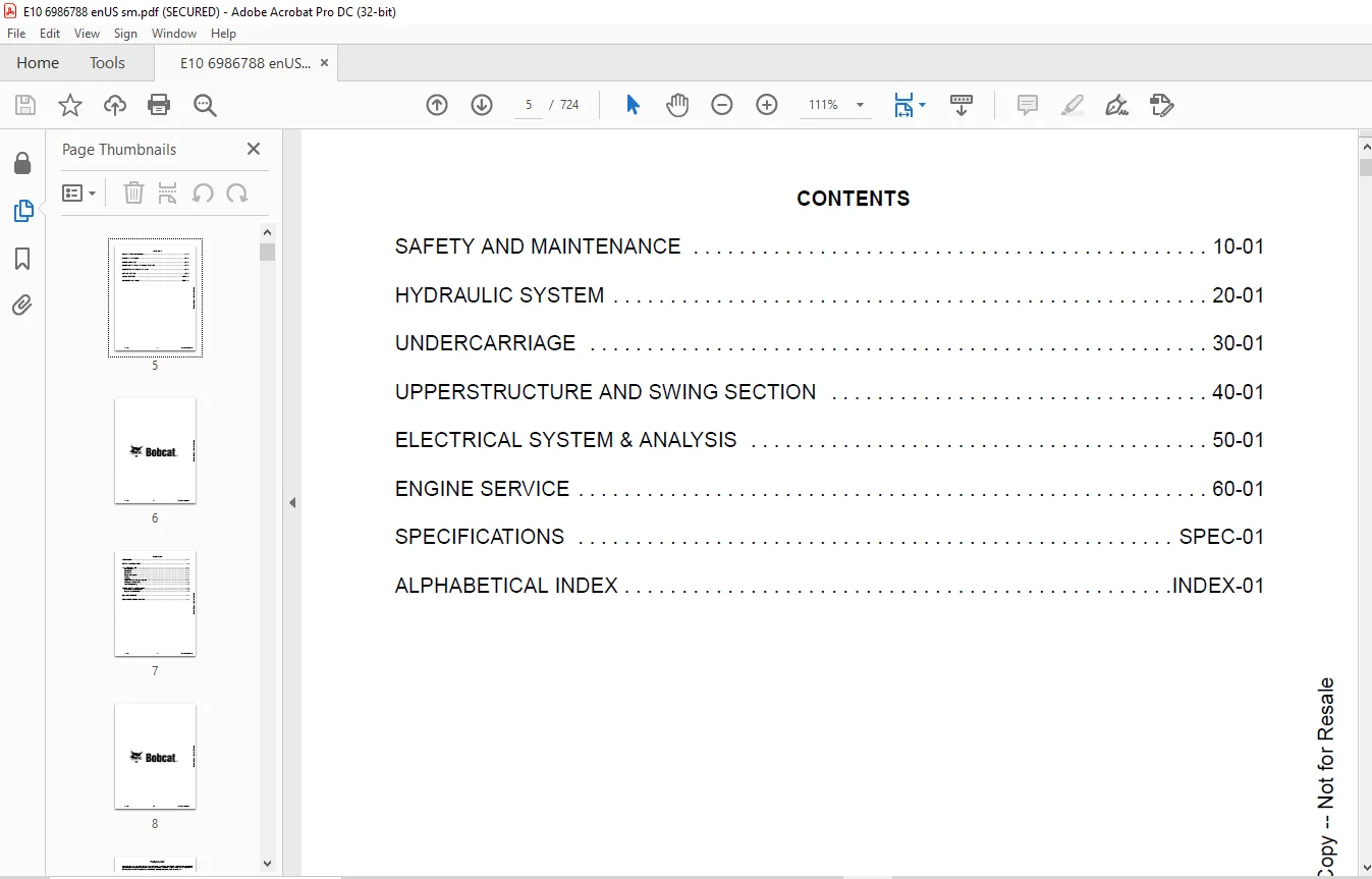
TABLE OF CONTENTS:
Bobcat E10 Compact Excavator Service Manual 6986788 (08-20) – PDF DOWNLOAD
MAINTENANCE SAFETY 3
CONTENTS 5
FOREWORD 7
FOREWORD 9
SAFETY INSTRUCTIONS 11
FIRE PREVENTION 13
Maintenance 13
Operation 13
Electrical 13
Hydraulic System 13
Fueling 13
Starting 13
Spark Arrester Exhaust System 13
Welding And Grinding 14
Fire Extinguishers 14
SERIAL NUMBER LOCATIONS 15
Excavator Serial Number 15
Engine Serial Number 15
DELIVERY REPORT 16
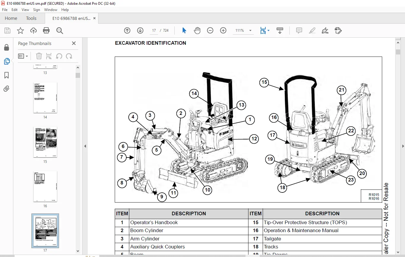
EXCAVATOR IDENTIFICATION 17
SAFETY AND MAINTENANCE 19
LIFTING AND BLOCKING THE EXCAVATOR 21
Procedure 21
UPPERSTRUCTURE SLEW LOCK 23
Operation 23
LIFTING THE EXCAVATOR 25
Procedure 25
TRANSPORTING THE EXCAVATOR ON A TRAILER 27
Loading And Unloading 27
Fastening 28
FOLD-DOWN TOPS 29
TOPS Position 29
TOPS Approved 29
Lowering The Fold Down TOPS 30
Raising The Fold Down TOPS 31
TAILGATE 33
Opening And Closing The Tailgate 33
SERVICE SCHEDULE 35
Contents Of The Inspection Checkbook (Logbook) 37
AIR CLEANER SERVICE 39
Daily Check 39
Replacing The Filter Elements 39
ENGINE COOLING SYSTEM 41
Cleaning 41
Checking Level 41
Removing And Replacing The Coolant 42
FUEL SYSTEM 43
Fuel Specifications 43
Biodiesel Blend Fuel 43
Filling The Fuel Tank 44
Fuel Filter 44
Draining The Fuel Tank 45
Removing Air From The Fuel System 45
ENGINE LUBRICATION SYSTEM 47
Checking And Adding Engine Oil 47
Engine Oil Chart 47
Replacing Oil And Filter 48
HYDRAULIC SYSTEM 49
Checking And Adding Fluid 49
Hydraulic / Hydrostatic Fluid Chart 50
Removing And Replacing The Hydraulic Filter 50
Removing And Replacing Hydraulic Fluid 51
LUBRICATION OF THE EXCAVATOR 53
Lubrication Locations 53
TRAVEL MOTOR 57
Checking And Adding Oil 57
Removing And Replacing Oil 57
SPARK ARRESTER MUFFLER 59
Cleaning Procedure 59
ALTERNATOR BELT 61
Belt Adjustment 61
Belt Replacement 62
SEAT BELT 63
Inspection And Maintenance 63
CONTROL CONSOLE LOCKOUTS 65
Inspection And Maintenance 65
EXCAVATOR STORAGE AND RETURN TO SERVICE 67
Storage 67
Return To Service 67
STOPPING THE ENGINE AND LEAVING THE EXCAVATOR 69
Procedure 69
MOTION ALARM 71
Description 71
Inspecting 71
Adjusting Switch Position 72
REMOTE START TOOL KIT – MEL1563 73
Remote Start Tool – MEL1563 73
Service Tool Harness Communicator – MEL1566 75
REMOTE START TOOL (SERVICE TOOL) KIT – 7003031 77
Description 77
Remote Start Tool (Service Tool) – 7003030 78
Excavator Service Tool Harness – 6689747 79
Computer Service Tool Harness – 6689746 80
HYDRAULIC SYSTEM 81
HYDRAULIC / HYDROSTATIC SCHEMATICS 87
HYDRAULIC SYSTEM INFORMATION 95
Glossary Of Hydraulic / Hydrostatic Symbols 95
Troubleshooting The Hydraulic Circuit 99
Troubleshooting The Cylinder Circuit 100
Troubleshooting The Swing (Upperstructure Slew) Circuit 101
Troubleshooting The Travel Circuit 102
CYLINDER (BOOM) 103
Testing 103
Removal And Installation 104
Parts Identification 106
Disassembly 107
Assembly 109
CYLINDER (ARM) 113
Testing 113
Removal And Installation 115
Parts Identification 116
Disassembly 117
Assembly 119
CYLINDER (BOOM SWING) 123
Testing 123
Removal And Installation 124
Parts Identification (Earlier Models) 126
Disassembly (Earlier Models) 127
Assembly (Earlier Models) 129
Parts Identification (Later Models) 132
Disassembly (Later Models) 133
Assembly (Later Models) 135
CYLINDER (BUCKET) 139
Testing 139
Removal And Installation 140
Parts Identification 142
Disassembly 143
Assembly 145
CYLINDER (BLADE) 149
Testing 149
Removal And Installation 150
Parts Identification (Earlier Models) 151
Disassembly (Earlier Models) 152
Assembly (Earlier Models) 154
Parts Identification (Later Models) 157
Disassembly (Later Models) 158
Assembly (Later Models) 160
CYLINDER (TRACK FRAME EXPANSION) 163
Testing 163
Removal And Installation 164
Parts Identification (Earlier Models) 168
Disassembly (Earlier Models) 169
Assembly (Earlier Models) 171
Parts Identification (Later Models) 174
Disassembly (Later Models) 175
Assembly (Later Models) 177
VALVE (MAIN RELIEF) 181
Testing And Adjusting 181
VALVE (PORT RELIEF) 183
Testing And Adjusting 183
VALVE (PRESSURE REDUCING) 185
Testing And Adjusting 185
HYDRAULIC CONTROL VALVE 187
Description 187
Removal And Installation 187
Parts Identification 196
Disassembly 197
Left Travel Valve Section Disassembly And Assembly 198
Slew Valve Section Disassembly And Assembly 201
Arm Valve Section Disassembly And Assembly 205
Boom Swing Valve Section Disassembly And Assembly 209
Auxiliary Valve Section Disassembly And Assembly 214
Blade Valve Section Disassembly And Assembly 218
Bucket Valve Section Disassembly And Assembly 222
Boom Valve Section Disassembly And Assembly 226
Right Travel Valve Section Disassembly And Assembly 231
Assembly 234
HYDRAULIC PUMP 239
Description 239
Testing The Hydraulic Pump 239
Removal And Installation 241
Parts Identification 243
Disassembly 244
Assembly 247
MANIFOLD ASSEMBLY / ACCUMULATOR 251
Description 251
Removal And Installation 251
Parts Identification 254
Disassembly 255
Assembly 261
TRAVEL MOTOR 267
Description 267
Removal And Installation 267
Parts Identification 268
Disassembly 269
Assembly 276
SWIVEL JOINT (S/N 133P14286 & ABOVE, B4K911001 & ABOVE AND B4PD11001 & ABOVE) 285
Description 285
Removal And Installation 285
Parts Identification 288
Disassembly 289
Assembly 291
SWIVEL JOINT (S/N A33P13634 – A33P14285) 293
Description 293
Removal And Installation 293
Parts Identification 296
Disassembly 297
Assembly 299
SWIVEL JOINT (S/N A33P12838 – A33P13633) 301
Description 301
Removal And Installation 301
Parts Identification 304
Disassembly 305
Assembly 307
SWIVEL JOINT (S/N A33P11001 – A33P12837) 311
Description 311
Removal And Installation 311
Parts Identification 314
Disassembly 315
Assembly 317
SWING MOTOR 321
Description 321
Removal And Installation 321
Parts Identification 327
Disassembly 328
Assembly 334
CONTROL PATTERN SELECTOR VALVE 341
Description 341
Removal And Installation 341
Disassembly And Assembly 342
CONTROL LEVER (JOYSTICK) (RIGHT) (S/N A33S13155 & ABOVE, B4K911001 & ABOVE AND B4PD11001 & ABOVE) 345
Description 345
Testing 345
Handle Removal And Installation 346
Removal And Installation 347
Parts Identification 349
Disassembly 350
Assembly 354
CONTROL LEVER (JOYSTICK) (RIGHT) (S/N A33P11001 – A33P13154) 359
Description 359
Testing 359
Handle Removal And Installation 360
Removal And Installation 361
Parts Identification 363
Disassembly 364
Assembly 368
CONTROL LEVER (JOYSTICK) (LEFT) (S/N A33P13155 & ABOVE, B4K911001 & ABOVE AND B4PD11001 & ABOVE) 373
Description 373
Testing 373
Handle Removal And Installation 374
Removal And Installation 376
Parts Identification 377
Disassembly 378
Assembly 382
CONTROL LEVER (JOYSTICK) (LEFT) (S/N A33P11001 – A33P13154) 387
Description 387
Testing 387
Handle Removal And Installation 389
Removal And Installation 391
Parts Identification 392
Disassembly 393
Assembly 397
HYDRAULIC RESERVOIR 401
Description 401
Removal And Installation 401
OIL COOLER 407
Description 407
Removal And Installation 407
ELECTRIC BLADE / TRACK EXPAND VALVE 409
Description 409
Block Removal And Installation 409
Solenoid Removal And Installation 410
Block Disassembly And Assembly 411
TRACK EXPAND VALVE 413
Description 413
Block Removal And Installation 413
Control Handle Removal And Installation 414
Block Disassembly And Assembly 415
BUILD-UP VALVE 417
Description 417
Removal And Installation 417
Disassembly And Assembly 419
TWO SPEED CONTROL VALVE 421
Description 421
Block Removal And Installation 421
Solenoid Removal And Installation 423
Block Disassembly And Assembly 424
UNDERCARRIAGE 427
BLADE 429
Description 429
Extension Removal And Installation 429
Blade Removal And Installation 430
TRACK UNDERCARRIAGE COMPONENTS 431
Description 431
Track Lug Height 431
Checking Tension 432
Adjusting Tension 433
Track Removal And Installation 434
Idler Removal And Installation 435
Idler Parts Identification 436
Idler Disassembly 437
Idler Assembly 438
Track Tensioner Removal And Installation 439
Track Tensioner Disassembly And Assembly 440
Roller Removal And Installation 440
Roller Parts Identification 441
Roller Disassembly 442
Roller Assembly 443
Removal And Installation Of Expandable Track Frame 446
TRACK MAINTENANCE 447
Track Damage Identification 447
SWING CIRCLE GEAR 459
Removal And Installation 459
UPPERSTRUCTURE AND SWING SECTION 461
UPPERSTRUCTURE 465
Description 465
Removal 465
Installation 469
TOPS 475
Removal And Installation 475
SEAT 477
Removal And Installation 477
RIGHT CONSOLE 479
Joystick Console Cover Removal And Installation 479
Gas Spring Removal And Installation 480
Compression Spring Removal And Installation 480
Lever Removal And Installation 481
Joystick Console Frame Removal And Installation 482
Joystick Console Frame Disassembly And Assembly 482
LEFT CONSOLE 485
Joystick Console Cover Removal And Installation 485
Gas Spring Removal And Installation 486
Compression Spring Removal And Installation 486
Lever Removal And Installation 487
Joystick Console Frame Removal And Installation 488
Joystick Console Frame Disassembly And Assembly 488
ENGINE SPEED CONTROL 491
Removal And Installation 491
Cable Removal 493
Cable Installation 495
BLADE CONTROL 499
Removal And Installation 499
Disassembly And Assembly 501
Two Speed Switch Removal And Installation 502
SWING LOCK 505
Removal And Installation 505
Disassembly And Assembly 505
RIGHT PEDAL AND LINKAGE 507
Pedal Removal And Installation 507
Linkage Removal And Installation 507
Linkage Disassembly And Assembly 509
TRAVEL CONTROLS 511
Right Hand Travel Control Removal And Installation 511
Right Hand Travel Control Disassembly And Assembly 511
Left Hand Travel Control Removal And Installation 512
Left Hand Travel Control Disassembly And Assembly 513
LEFT PEDAL AND LINKAGE 515
Pedal Removal And Installation 515
Control Linkage Removal And Installation 515
Control Linkage Disassembly And Assembly 517
FLOOR PANELS 519
Description 519
Left Floor Panel Removal And Installation 519
Right Floor Panel Removal And Installation 519
FUEL TANK 521
Removal And Installation 521
HORN 523
Removal And Installation 523
SWING FRAME 525
Description 525
Removal And Installation 525
Bushing Removal 526
Bushing Installation 527
Boom Pivot Bushing Removal 528
Boom Pivot Bushing Installation 528
BOOM 529
Description 529
Removal And Installation 529
ARM 531
Description 531
Removal And Installation 531
Arm To Boom Bushing Removal And Installation 532
Arm To Bucket And Bucket Link Bushing Removal And Installation 532
BUCKET 533
Removal And Installation 533
TAILGATE 535
Removal And Installation 535
Latch Removal And Installation 536
COUNTERWEIGHTS 537
Rear Counterweight Removal And Installation 537
Left Side Counterweight Removal And Installation 537
Right Side Counterweight Removal And Installation 538
SIDE COVERS 541
Upper Left Side Cover Removal And Installation 541
Upper Right Side Cover Removal And Installation 541
Lower Left Side Cover Removal And Installation 542
Lower Right Side Cover Removal And Installation 543
INSTRUMENT PANEL 545
Removal And Installation 545
Disassembly And Assembly 546
QUICK COUPLER (KLAC™ SYSTEM) 549
Troubleshooting 549
Daily Inspection 549
Removal And Installation 550
Parts Identification 552
Disassembly 553
Assembly 555
QUICK COUPLER (LEHNHOFF® SYSTEM) 557
Troubleshooting 557
Daily Inspection 557
Removal (MS03 And MS08) 558
Installation (MS03 And MS08) 559
Parts Identification (MS03) 560
Disassembly And Assembly (MS03) 561
Parts Identification (MS08) 562
Disassembly (MS08) 563
Assembly (MS08) 566
ELECTRICAL SYSTEM & ANALYSIS 571
ELECTRICAL SCHEMATICS 573
ELECTRICAL SYSTEM INFORMATION 575
Glossary Of Electrical Symbols 575
Troubleshooting 578
Description 579
Fuse And Relay Location / Identification 579
Fuel Timer Location / Identification 580
BATTERY 581
Location 581
Servicing 581
Removal And Installation 583
Using A Booster Battery (Jump Starting) 585
ALTERNATOR 587
Description 587
Tests 587
Alternator Output Test 588
Full Field Test 588
Alternator Regulator Test 589
Alternator Regulator Test With Voltmeter 589
Removal And Installation 590
Charging System Inspection 592
Parts Identification 593
STARTER 595
Removal And Installation 595
Parts Identification 596
Cleaning And Inspection 596
LIGHTS 597
Boom Light Removal And Installation 597
Light Bulb Removal And Installation 597
Light Switch Removal And Installation 598
MICROSWITCH 601
Testing Left Console Microswitch 601
Left Console Microswitch Removal And Installation 602
Testing Right Console Microswitch 603
Right Console Microswitch Removal And Installation 603
FUEL LEVEL SENDER 605
Removal And Installation 605
Testing 605
ENGINE SERVICE 607
ENGINE INFORMATION 609
Description 609
Specifications 610
Torque Values 614
Troubleshooting 616
Removal And Installation 617
Engine Mount Replacement 627
Compression – Checking 628
MUFFLER 629
Removal And Installation 629
AIR CLEANER 633
Removal And Installation 633
ENGINE COOLING SYSTEM 635
Radiator Removal And Installation 635
Water Pump Removal And Installation 636
Water Pump Disassembly And Assembly 636
Thermostat Removal And Installation 637
Thermostat – Checking 637
LUBRICATION SYSTEM 639
Oil Pan Removal And Installation 639
Oil Pump Removal And Installation 640
Oil Pump – Service 640
Engine Oil Pressure – Testing 641
Relief Valve 641
FUEL SYSTEM 643
Fuel Shutoff Solenoid Removal And Installation 643
Fuel Shutoff Timer Removal And Installation 643
Fuel Injection Pump – Checking 644
Fuel Injection Pump Removal And Installation 645
Fuel Injection Pump – Timing 647
Fuel Camshaft Removal And Installation 649
Fuel Camshaft Governor 649
Fuel Injector Removal And Installation 650
Fuel Injector Nozzle Pressure – Checking 651
Valve Seat Tightness 653
CYLINDER HEAD 655
Glow Plug Removal And Installation 655
Valve Clearance Adjustment 656
Valve Timing – Checking 657
Cylinder Head Removal And Installation 657
Cylinder Head Disassembly And Assembly 659
Cylinder Head – Servicing 660
Cylinder Head Top Clearance 660
Valve Guide – Checking 661
Valve And Valve Seat Reconditioning 663
Valve Spring 664
Valve Tappets 665
Rocker Arm And Shaft – Checking 666
CRANKSHAFT AND PISTONS 667
Piston And Connecting Rod Removal And Installation 667
Piston And Connecting Rod – Servicing 670
Cylinder Bore – Checking 672
Connecting Rod Alignment 672
Crankshaft And Bearings Removal And Installation 673
Crankshaft And Bearings – Servicing 675
CAMSHAFT AND TIMING GEARS 679
Timing Gearcase Cover Removal And Installation 679
Timing Gears Checking Backlash 681
Idler Gear And Camshaft Removal And Installation 681
Idler Gear And Shaft – Servicing 684
FLYWHEEL AND HOUSING 685
Removal And Installation 685
Hydraulic Pump Coupler Removal And Installation 686
Flywheel Removal And Installation 686
Rear End Plate Removal And Installation 687
SPECIFICATIONS 689
EXCAVATOR SPECIFICATIONS 691
Machine Dimensions 691
Working Range 692
Rated Lift Capacity 693
Performance 694
Function Time 694
Weights 694
Controls 694
Engine (S/N B4PD11001 & Above) 695
Engine (S/N B4K911001 & Above) 695
Engine (S/N A33P11001 & Above) 696
Electrical 696
Hydraulic System 696
Hydraulic Cylinders 697
Drive System 697
Traction 698
Track width, rubber, standard 698
Fluid Capacities 698
Cooling system 698
Instrumentation 698
Environmental 698
Temperature Range 699
TECHNICAL SERVICE GUIDE SPECIFICATIONS 701
Engine 701
Engine Torques 701
Cooling System 701
Excavator Torques 702
TORQUE SPECIFICATIONS FOR BOLTS 703
Torque For General SAE Bolts 703
Torque For General Metric Bolts 704
HYDRAULIC CONNECTION SPECIFICATIONS 705
O-ring Face Seal Connection 705
Straight Thread O-ring Fitting 706
Tubelines And Hoses 706
Flare Fitting 707
Port Seal Fitting 708
HYDRAULIC FLUID SPECIFICATIONS 709
Specifications 709
CONVERSIONS 711
Decimal And Millimeter Equivalents 711
U S To Metric Conversion Chart 711
SERVICE TOOLS REQUIRED 713
Remote Start Tools 713
Hydraulic Tools 714
Engine Tools 717
Electrical Tools 719
General Tools 719
HVAC Tools 720
ALPHABETICAL INDEX 721
SERVICE SCHEDULE SYMBOLS 723
IMAGES PREVIEW OF THE MANUAL:
Contact us: [email protected]
https://vimeo.com/841442833?share=copy
PLEASE NOTE:
- This is the same manual used by the dealers to diagnose and troubleshoot your vehicle
- You will be directed to the download page as soon as the purchase is completed. The whole payment and downloading process will take anywhere between 2-5 minutes
- Need any other service / repair / parts manual, please feel free to contact [email protected] . We still have 50,000 manuals unlisted
s.m