Bobcat E14 Compact Excavator Service Manual SN AHNM11001 & Above – PDF DOWNLOAD
$31.95
Bobcat E14 Compact Excavator Service Manual SN AHNM11001 & Above – PDF DOWNLOAD
S/N AHNM11001 & Above
Description
Bobcat E14 Compact Excavator Service Manual SN AHNM11001 & Above – PDF DOWNLOAD
Bobcat E14 Compact Excavator Service Manual SN AHNM11001 & Above – PDF DOWNLOAD
FILE DETAILS:
Bobcat E14 Compact Excavator Service Manual SN AHNM11001 & Above – PDF DOWNLOAD
Language : English
Pages : 666
Downloadable : Yes
File Type : PDF
Size:19.4 mb
DESCRIPTION:
Bobcat E14 Compact Excavator Service Manual SN AHNM11001 & Above – PDF DOWNLOAD
S/N AHNM11001 & Above
FOREWORD:
This manual is for the Bobcat loader mechanic. It provides necessary servicing and adjustment procedures for the Bobcat loader and its component parts and systems. Refer to the Operation & Maintenance Manual for operating instructions, Starting procedure, daily checks, etc.
The following publications provide information on the safe use and maintenance of the Bobcat machine and attachments:
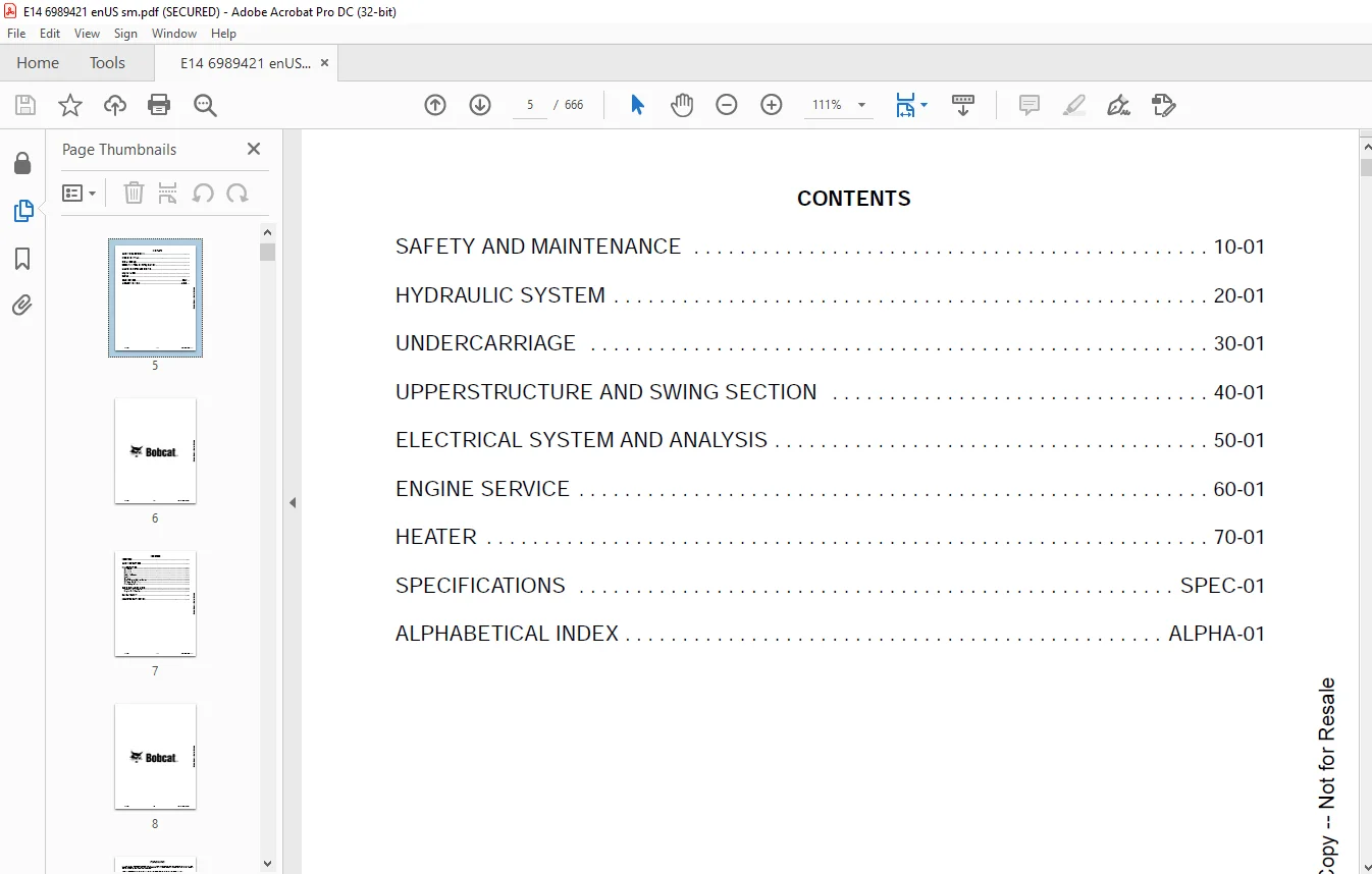
TABLE OF CONTENTS:
Bobcat E14 Compact Excavator Service Manual SN AHNM11001 & Above – PDF DOWNLOAD
MAINTENANCE SAFETY 3
CONTENTS 5
FOREWORD 7
FOREWORD 9
SAFETY INSTRUCTIONS 11
FIRE PREVENTION 13
Maintenance 13
Operation 13
Electrical 13
Hydraulic System 13
Fueling 13
Starting 13
Welding And Grinding 14
Fire Extinguishers 14
SERIAL NUMBER LOCATIONS 16
Excavator Serial Number 16
Engine Serial Number 16
DELIVERY REPORT 17
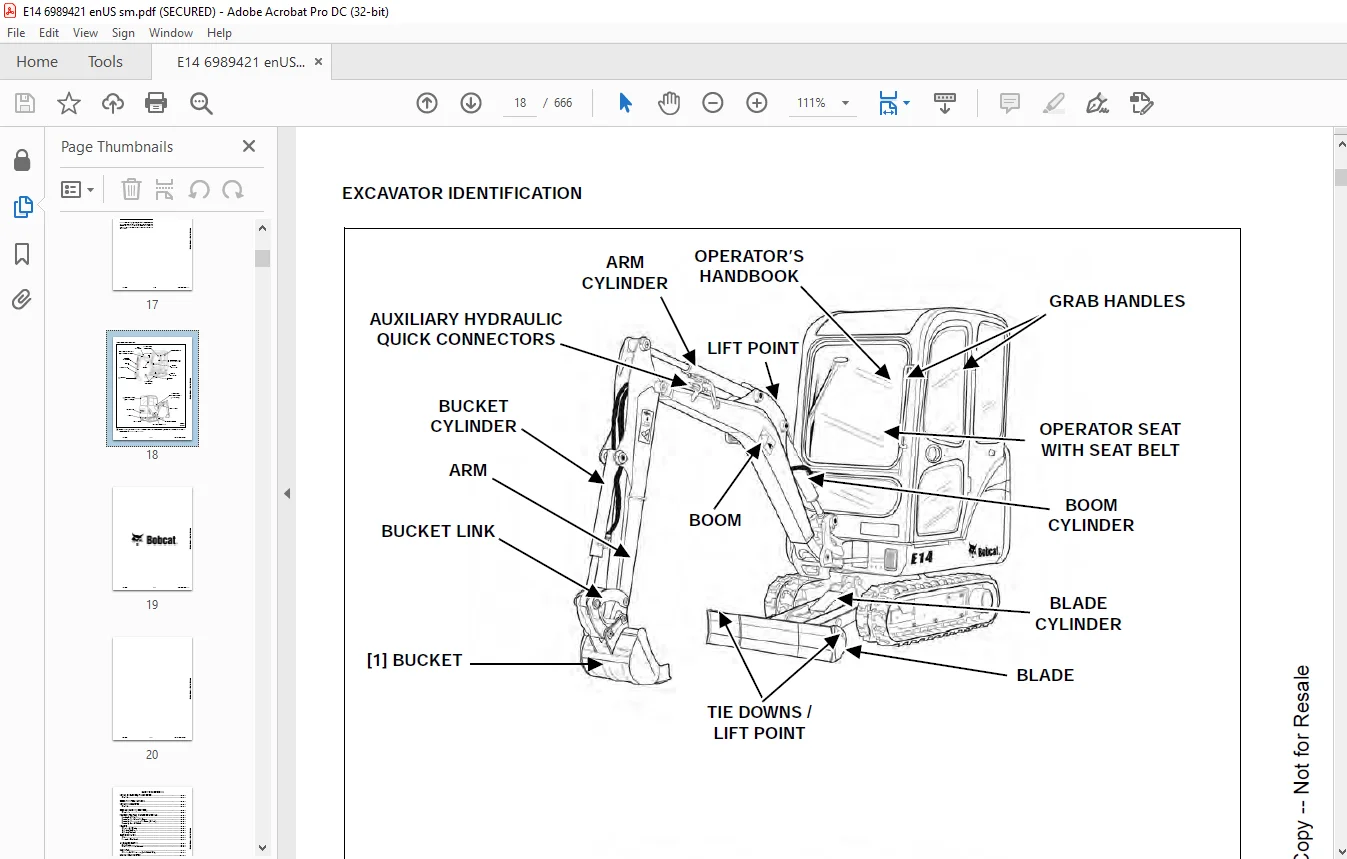
EXCAVATOR IDENTIFICATION 18
SAFETY AND MAINTENANCE 21
LIFTING AND BLOCKING THE EXCAVATOR 25
Procedure 25
UPPERSTRUCTURE SLEW LOCK 27
LIFTING THE EXCAVATOR 29
Procedure 29
OPERATOR CANOPY (ROPS / TOPS) 31
Description 31
OPERATOR CAB (ROPS / TOPS) 33
Description 33
Cab Door 33
Front Window 34
Front Wiper 35
Window Washer Reservoir 35
Right Side Windows 35
Heater 36
TRANSPORTING THE EXCAVATOR ON A TRAILER 39
Loading And Unloading 39
Fastening – Track Frame Tie Downs 40
Fastening – Upperstructure Tie Downs (Optional) 40
Fastening Arm – All Models 41
TAILGATE 43
Opening And Closing 43
Adjusting The Bumper 43
Adjusting The Latch 43
SERVICE SCHEDULE 45
Chart 45
Inspection Checkbook 46
AIR CLEANER SERVICE 47
Daily Check 47
Replacing The Filter Elements 47
CAB FILTER 49
Cleaning And Maintenance (Early Models Only) 49
ENGINE COOLING SYSTEM 51
Cleaning 51
Checking Level 51
Removing And Replacing Coolant 52
FUEL SYSTEM 55
Fuel Specifications 55
Biodiesel Blend Fuel 55
Filling The Fuel Tank 56
Fuel Filters 56
Draining The Fuel Tank 57
Removing Air From The Fuel System 57
ENGINE LUBRICATION SYSTEM 59
Checking And Adding Engine Oil 59
Engine Oil Chart 59
Removing And Replacing Oil And Filter 60
HYDRAULIC SYSTEM 61
Checking And Adding Hydraulic Fluid 61
Hydraulic / Hydrostatic Fluid Chart 61
Removing And Replacing The Hydraulic Filter 62
Removing And Replacing The Hydraulic Fluid 62
LUBRICATING THE EXCAVATOR 65
Lubrication Locations 65
TRAVEL MOTOR 69
Checking And Adding Oil 69
Removing And Replacing Oil 69
SPARK ARRESTER MUFFLER 71
Cleaning Procedure 71
SEAT BELT 73
Inspection And Maintenance 73
CONTROL CONSOLE LOCKOUTS 75
Inspection And Maintenance 75
PIVOT PINS 77
Inspection And Maintenance 77
EXCAVATOR STORAGE AND RETURN TO SERVICE 79
Storage 79
Return to Service 79
STOPPING THE ENGINE AND LEAVING THE EXCAVATOR 81
Procedure 81
EMERGENCY EXIT 83
Right Side Rear Window 83
Front Window 83
MOTION ALARM SYSTEM 85
Description 85
Inspecting 85
Adjusting Switch Position 86
REMOTE START TOOL KIT – MEL1563 87
Remote Start Tool – MEL1563 87
Service Tool Harness Control – MEL1565 88
Service Tool Harness Communicator – MEL1566 89
REMOTE START TOOL (SERVICE TOOL) KIT – 6689779 / 7003031 91
Description 91
Remote Start Tool (Service Tool) – 6689778 / 7003030 92
Excavator Service Tool Harness – 6689747 93
Computer Service Tool Harness – 6689746 94
HYDRAULIC SYSTEM 95
HYDRAULIC/HYDROSTATIC SCHEMATICS 99
HYDRAULIC SYSTEM INFORMATION 103
Glossary Of Hydraulic / Hydrostatic Symbols 103
Troubleshooting The Hydraulic Circuit 106
Troubleshooting The Cylinder Circuit 107
Troubleshooting The Swing (Upperstructure Slew) Circuit 108
Troubleshooting The Travel Circuit 109
BOOM CYLINDER 111
Testing 111
Removal And Installation 112
Parts Identification 115
Disassembly 116
Assembly 118
ARM CYLINDER 121
Testing 121
Removal And Installation 123
Parts Identification 125
Disassembly 126
Assembly 128
BOOM SWING CYLINDER 131
Testing 131
Removal And Installation 132
Parts Identification 134
Disassembly 135
Assembly 137
BUCKET CYLINDER 141
Testing 141
Removal And Installation 142
Parts Identification 144
Disassembly 145
Assembly 147
BLADE CYLINDER 151
Testing 151
Removal And Installation 152
Parts Identification 154
Disassembly 155
Assembly 157
TRACK FRAME EXPANSION CYLINDER 161
Testing 161
Removal And Installation 162
Parts Identification 166
Disassembly 167
Assembly 169
MAIN RELIEF VALVE 173
Testing And Adjusting The Main Relief Valve 173
PORT RELIEF VALVES 175
Testing And Adjusting The Port Relief Valve Pressure 175
CROSSPORT RELIEF VALVES 177
Testing And Adjusting The Crossport Relief Valve 177
PRESSURE REDUCING VALVE 179
Testing And Adjusting The Pressure Reducing Valve 179
HYDRAULIC CONTROL VALVE 181
Description 181
Removal And Installation 181
Identification Chart 185
Disassembly 186
Blade Valve Section Disassembly And Assembly 187
Slew Valve Section Disassembly And Assembly 192
Left Travel Valve Section Disassembly And Assembly 196
Boom Valve Section Disassembly And Assembly 200
Auxiliary Valve Section Disassembly And Assembly 203
Bucket Valve Section Disassembly And Assembly 207
Arm Valve Section Disassembly And Assembly 210
Boom Swing Valve Section Disassembly And Assembly 213
Right Travel Valve Section Disassembly And Assembly 217
Assembly 221
HYDRAULIC PUMP 227
Description 227
Testing The Hydraulic Pump 227
Removal And Installation 229
Parts Identification 231
Disassembly 232
Assembly 234
MANIFOLD ASSEMBLY / ACCUMULATOR 239
Description 239
Removal And Installation 239
Parts Identification 241
Disassembly 242
Assembly 249
TRAVEL MOTOR 257
Description 257
Removal And Installation 257
Parts Identification 258
Disassembly 259
Assembly 265
SWIVEL JOINT 273
Description 273
Removal And Installation 273
Parts Identification (S/N AHNM11001 To AHNM22000) 276
Parts Identification (AHNM22001 & Above) 277
Disassembly 278
Assembly 280
SWING MOTOR 283
Description 283
Removal And Installation 283
Parts Identification 284
Disassembly 285
Assembly 291
RIGHT CONTROL LEVER (JOYSTICK) 299
Description 299
Testing 299
Handle Removal And Installation 301
Removal And Installation 302
Parts Identification 303
Disassembly 304
Assembly 309
LEFT CONTROL LEVER (JOYSTICK) 313
Description 313
Testing 313
Handle Removal And Installation 315
Removal And Installation 317
Parts Identification 318
Disassembly 319
Assembly 324
HYDRAULIC FILTER 329
Description 329
Housing Removal and Installation 329
HYDRAULIC RESERVOIR 331
Description 331
Removal And Installation 331
OIL COOLER 333
Description 333
Removal And Installation 333
BLADE / TRACK EXPANSION SOLENOID BLOCK (FOR MODEL E14 S/N AHNM11001 – 12018) 335
Description 335
Block Removal And Installation 335
Solenoid Removal And Installation 336
Block Disassembly And Assembly 337
BLADE / TRACK EXPANSION SOLENOID BLOCK (FOR MODEL E14 S/N AHNM12019 & ABOVE) 339
Description 339
Block Removal And Installation 339
Solenoid Removal And Installation 340
Block Disassembly And Assembly 341
SLEW LOCK VALVE 343
Description 343
Removal And Installation 343
Parts Identification 345
Disassembly And Assembly 346
TWO SPEED VALVE 351
Description 351
Block Removal And Installation 351
Solenoid Removal And Installation 352
Block Disassembly And Assembly 353
UNDERCARRIAGE 355
BLADE 357
Description 357
Extension Removal And Installation 357
Blade Removal And Installation 358
TRACK UNDERCARRIAGE COMPONENTS 359
Description 359
Track Lug Height 359
Checking Tension 359
Adjusting Tension 360
Track Removal And Installation 361
Idler Removal And Installation 362
Idler Parts Identification 363
Idler Disassembly 364
Idler Assembly 365
Track Tensioner Removal And Installation 368
Track Tensioner Disassembly And Assembly 368
Roller Removal And Installation 369
Roller Parts Identification 370
Roller Disassembly 371
Roller Assembly 372
Sprocket Removal And Installation 374
TRACK MAINTENANCE 375
Track Damage Identification 375
SWING CIRCLE GEAR 387
Removal And Installation 387
UPPERSTRUCTURE AND SWING SECTION 389
UPPERSTRUCTURE 393
Description 393
Removal 393
Installation 395
CANOPY 397
Removal And Installation 397
CAB 401
Removal And Installation 401
Door Removal And Installation 405
Front Window Removal And Installation 406
Right Side Rear Sliding Window Removal And Installation 409
Right Side Front Sliding Window Removal And Installation 410
Glass Removal 410
Right Side Front And Rear Sliding Window Weather Strip Removal And Installation 411
Right Side Front And Rear Sliding Window Wiper Strip Removal And Installation 411
Glass Installation 412
SEAT AND SEAT MOUNT (FOR MODEL E14 S/N AHNM11001 – 12018) 415
Seat Mount Removal And Installation 415
SEAT AND SEAT MOUNT (FOR MODEL E14 S/N AHNM12019 & ABOVE) 417
Seat Mount Removal And Installation 417
RIGHT CONSOLE 419
Description 419
Joystick Console Cover (Bottom) Removal And Installation 419
Joystick Console Cover (Top) Removal And Installation 420
Joystick Console Cover (Top) Disassembly And Assembly 421
Compression Spring Removal And Installation (Canopy Only) 422
Compression Spring Disassembly And Assembly (Canopy Only) 423
Lever Removal And Installation (Canopy Only) 424
Joystick Console Frame Removal And Installation 426
Joystick Console Frame Disassembly And Assembly 427
Right Rear Console Cover Removal And Installation 428
Right Rear Console Cover Disassembly and Assembly 429
Right Rear Console Frame Removal And Installation 430
LEFT CONSOLE 433
Description 433
Joystick Console Cover (Bottom) Removal And Installation 433
Joystick Console Cover (Top) Removal And Installation 434
Compression Spring Removal And Installation 435
Compression Spring Disassembly And Assembly 436
Lever Removal And Installation 438
Joystick Console Frame Removal And Installation 439
Joystick Console Frame Disassembly And Assembly 440
Left Rear Console Cover Removal And Installation 440
Left Rear Console Frame Removal And Installation 441
ENGINE SPEED CONTROL 443
Removal And Installation 443
Cable Removal And Installation 444
BLADE CONTROL 447
Removal And Installation 447
Disassembly And Assembly 448
Cable Removal And Installation 450
UPPERSTRUCTURE SLEW LOCK 451
Removal And Installation 451
Disassembly And Assembly 451
CONTROL LINKAGE ASSEMBLY 453
Description 453
Removal And Installation 453
Right Half Of Control Linkage Disassembly And Assembly 455
Left Half Of Control Linkage Disassembly And Assembly 457
Bracket Of Control Linkage Disassembly And Assembly 460
FLOOR MAT AND FLOOR PANELS 461
Description 461
Rear Floor Panel Removal And Installation 461
Front Floor Panel Removal And Installation 462
Linkage Rod Removal And Installation 463
Linkage Rod Adjustment 463
Boom Swing Pedal Removal And Installation 465
Boom Swing Pedal Disassembly And Assembly 466
Right Travel Lever Removal And Installation 467
Right Travel Lever Disassembly And Assembly 467
Left Travel Lever Removal And Installation 468
Left Travel Lever Disassembly And Assembly 468
Auxiliary Pedal Removal And Installation 469
Auxiliary Pedal Disassembly And Assembly 469
FUEL TANK 471
Removal And Installation 471
HORN 473
Removal And Installation 473
SWING FRAME 475
Description 475
Removal And Installation 475
Bushing Removal And Installation 477
Swing Frame Bushing Removal 477
Swing Frame Bushing Installation 478
Boom Pivot Bushing Removal 479
Boom Pivot Bushing Installation 479
BOOM 481
Description 481
Removal And Installation 481
Boom Bushing Removal And Installation 484
ARM 485
Description 485
Removal And Installation 485
Arm To Boom Bushing Removal And Installation 486
Arm To Bucket And Bucket Link Bushing Removal And Installation 487
BUCKET 489
Removal And Installation 489
TAILGATE 491
Removal And Installation 491
Latch Removal And Installation 492
ELECTRICAL SYSTEM AND ANALYSIS 493
ELECTRICAL SCHEMATICS 495
ELECTRICAL SYSTEM INFORMATION 497
Glossary Of Electrical Symbols 497
Troubleshooting 500
Description 501
Fuse And Relay Location / Identification 501
Fuel Timer And Diode Location / Identification 502
BATTERY 503
Battery Maintenance 503
Removal And Installation 504
Using A Booster Battery (Jump Starting) 505
ALTERNATOR 507
Description 507
Tests 507
Alternator Output Test 508
Full Field Test 508
Alternator Regulator Test 509
Alternator Regulator Test With Voltmeter 509
Removal And Installation 510
Belt Adjustment (S/N AHNM11001 – 12018) 513
Belt Adjustment (S/N AHNM12019 & Above) 514
Belt Adjustment (All Models) 515
Belt Replacement 515
Charging System Inspection 516
Parts Identification 517
STARTER 519
Removal And Installation 519
Parts Identification 522
Cleaning And Inspection 522
LIGHTS 523
Upperstructure Light Removal And Installation 523
Upperstructure Light Disassembly And Assembly 523
Boom Light Removal And Installation 524
Boom Light Disassembly And Assembly 524
Light Switch Removal And Installation 525
MICROSWITCH 527
Testing Left Console Microswitch 527
Left Console Microswitch Removal And Installation 528
Testing Right Console Microswitch 528
Right Console Microswitch Removal And Installation 530
FUEL LEVEL SENDER 531
Testing 531
Removal And Installation 531
ENGINE SERVICE 533
ENGINE INFORMATION 537
Description 537
Specifications 538
Engine 538
Fuel Injector Nozzles 538
Fuel Injection Pump 538
Cylinder Head 538
Valves 539
Valve Springs 539
Rocker Arms 539
Camshaft 539
Cylinders 540
Piston Rings 540
Pistons 540
Connecting Rods 540
Crankshaft 541
Oil Pump 541
Thermostat 541
Torque Values 542
Troubleshooting 543
Engine Removal And Installation 544
Engine Mount Replacement 551
Compression – Checking 552
SPARK ARRESTER MUFFLER 553
Removal And Installation 553
AIR CLEANER 555
Housing Removal And Installation 555
ENGINE COOLING SYSTEM 557
Radiator Removal And Installation 557
Water Pump Removal And Installation 562
Water Pump Disassembly And Assembly 562
Thermostat Removal And Installation 563
Testing The Thermostat 563
LUBRICATION SYSTEM 565
Oil Pan Removal And Installation 565
Oil Pump Removal And Installation 566
Oil Pump Inspection 566
Engine Oil Pressure – Testing 567
Relief Valve 568
FUEL SYSTEM 569
Fuel Camshaft Removal And Installation 569
Fuel Camshaft Governor Disassembly And Assembly 569
Fuel Shutoff Solenoid – Checking 570
Fuel Shutoff Solenoid – Removal And Installation 570
Fuel Shutoff Timer Removal And Installation 571
Fuel Injection Pump – Checking 571
Fuel Injection Pump Removal And Installation 572
Injection Pump – Timing 574
Fuel Injector Removal And Installation 576
Fuel Injector Nozzle Pressure – Checking 577
Nozzle Spray Condition 578
Valve Seat Tightness 578
CYLINDER HEAD 579
Glow Plug Removal And Installation 579
Glow Plugs – Testing 580
Valve Clearance Adjustment 580
Valve Timing, Checking 581
Cylinder Head Removal And Installation 582
Cylinder Head Disassembly And Assembly 584
Cylinder Head – Servicing 585
Cylinder Head Top Clearance 586
Valve Guide – Checking 586
Reconditioning The Valve And Valve Seat 588
Valve Spring 589
Valve Tappets 590
Rocker Arm And Shaft – Checking 591
CRANKSHAFT AND PISTONS 593
Piston And Connecting Rod Removal And Installation 593
Piston And Connecting Rod – Servicing 595
Cylinder Bore Checking 597
Connecting Rod Alignment 597
Crankshaft Gear Removal And Installation 598
Crankshaft And Bearings Removal And Installation 599
Crankshaft And Bearings – Servicing 602
CAMSHAFT AND TIMING GEARS 605
Timing Gearcase Cover Removal And Installation 605
Timing Gears Backlash – Checking 607
Idler Gear And Shaft Removal And Installation 607
Camshaft – Servicing 608
Idler Gear And Shaft Servicing 610
FLYWHEEL AND HOUSING 611
Flywheel Housing Removal And Installation 611
Hydraulic Pump Coupler Removal And Installation 612
Flywheel Removal 612
Flywheel Installation 613
Rear End Plate Removal And Installation 613
HEATER 615
HEATER SYSTEM 617
Description 617
Components 617
REGULAR MAINTENANCE 619
Filter Element Removal And Installation 619
Heater Coil 619
HEATER UNIT 621
Removal And Installation 621
Louver Removal And Installation 622
Threaded Insert Removal And Installation 622
HEATER COIL 623
Removal And Installation 623
HEATER FAN 627
Removal And Installation 627
HEATER VALVE 631
Removal And Installation 631
SPECIFICATIONS 633
(E14) SPECIFICATIONS 635
Machine Dimensions 635
Lift Capacity 637
Performance 638
Controls 638
Engine 638
Hydraulic System 639
Hydraulic Cylinders 639
Hydraulic Cycle Times 640
Electrical 640
Instrumentation 640
Lights 640
Drive System 640
Slew System 640
Undercarriage 640
Crawler Track Design 640
Tracks 640
Type 640
Ground Pressure 641
Capacities 641
Fuel Tank 641
TECHNICAL SERVICE GUIDE SPECIFICATIONS 643
Engine 643
Engine Torques 643
Cooling System 643
Excavator Torques 643
TECHNICAL SERVICE GUIDE SPECIFICATIONS 645
Engine 645
Engine Torques 645
Cooling System 645
Excavator Torques 645
HYDRAULIC CONNECTION SPECIFICATIONS 647
O-ring Face Seal Connection 647
Straight Thread O-ring Fitting 647
Tubelines And Hoses 648
Flare Fitting 648
O-ring Flare Fitting 649
Port Seal Fitting 651
Push To Connect Fittings 652
HYDRAULIC FLUID SPECIFICATIONS 655
Specifications 655
CONVERSIONS 657
Decimal And Millimeter Equivalents 657
U S To Metric Conversion Chart 657
SERVICE TOOLS REQUIRED 659
Remote Start Tools 659
Hydraulic Tools 660
Engine Tools 662
HVAC Tools 664
ALPHABETICAL INDEX 665
IMAGES PREVIEW OF THE MANUAL:
Customer Support: [email protected]’
https://vimeo.com/841440914?share=copy
PLEASE NOTE:
- This is the SAME exact manual used by your dealers to fix your vehicle.
- The same can be yours in the next 2-3 mins as you will be directed to the download page immediately after paying for the manual.
- Any queries / doubts regarding your purchase, please feel free to contact [email protected]
s.m