Bobcat E16 Compact Excavator Service Manual SN AHLL11001 & Above – PDF DOWNLOAD
$31.95
Bobcat E16 Compact Excavator Service Manual SN AHLL11001 & Above – PDF DOWNLOAD
S/N AHLL11001 & Above
Description
Bobcat E16 Compact Excavator Service Manual SN AHLL11001 & Above – PDF DOWNLOAD
FILE DETAILS:
Bobcat E16 Compact Excavator Service Manual SN AHLL11001 & Above – PDF DOWNLOAD
Language : English
Pages : 689
Downloadable : Yes
File Type : PDF
Size:19.7 MB
DESCRIPTION:
Bobcat E16 Compact Excavator Service Manual SN AHLL11001 & Above – PDF DOWNLOAD
FOREWORD:
This manual is for the Bobcat loader mechanic. It provides necessary servicing and adjustment procedures for the Bobcat loader and its component parts and systems. Refer to the Operation & Maintenance Manual for operating instructions, Starting procedure, daily checks, etc.
The following publications provide information on the safe use and maintenance of the Bobcat machine and attachments:
TABLE OF CONTENTS:
Bobcat E16 Compact Excavator Service Manual SN AHLL11001 & Above – PDF DOWNLOAD
MAINTENANCE SAFETY 3
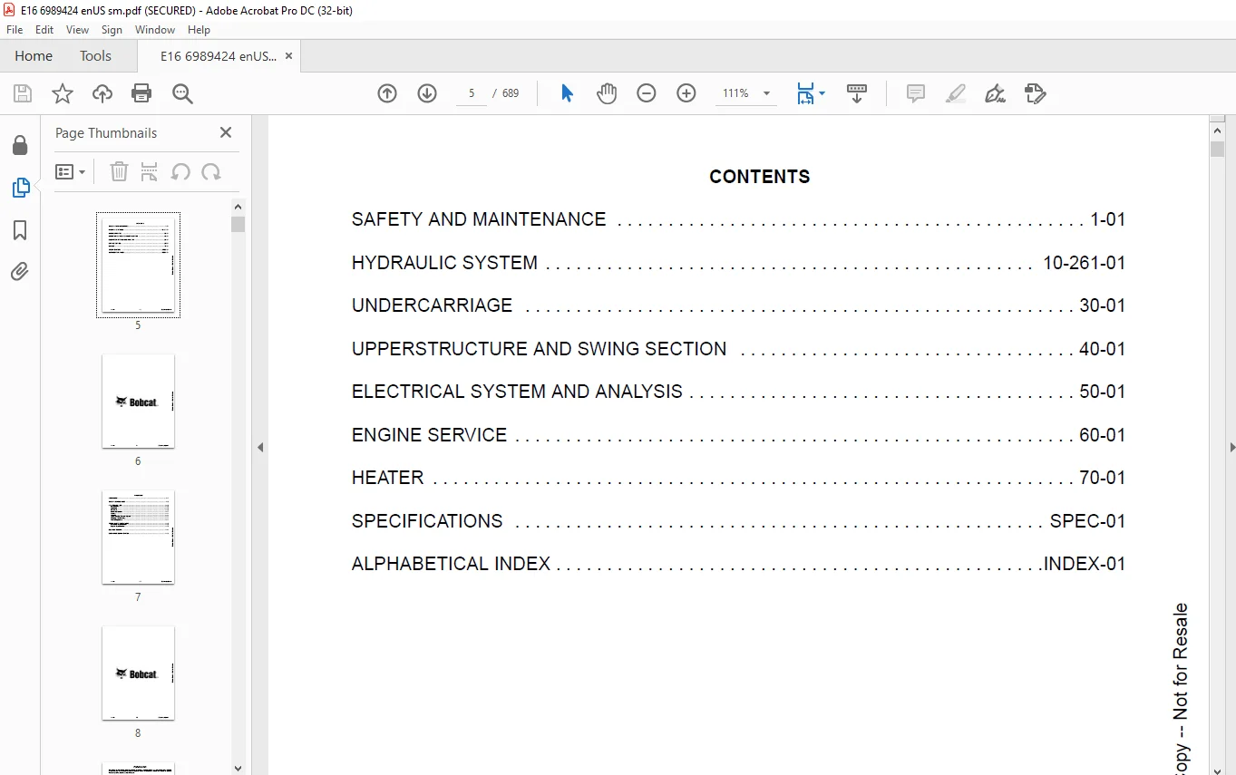
CONTENTS 5
FOREWORD 7
FOREWORD 9
SAFETY INSTRUCTIONS 11
FIRE PREVENTION 12
Maintenance 12
Operation 12
Electrical 12
Hydraulic System 13
Fueling 13
Starting 13
Spark Arrester Exhaust System 13
Welding And Grinding 13
Fire Extinguishers 13
SERIAL NUMBER LOCATIONS 15
Excavator Serial Number 15
Engine Serial Number 15
DELIVERY REPORT 16
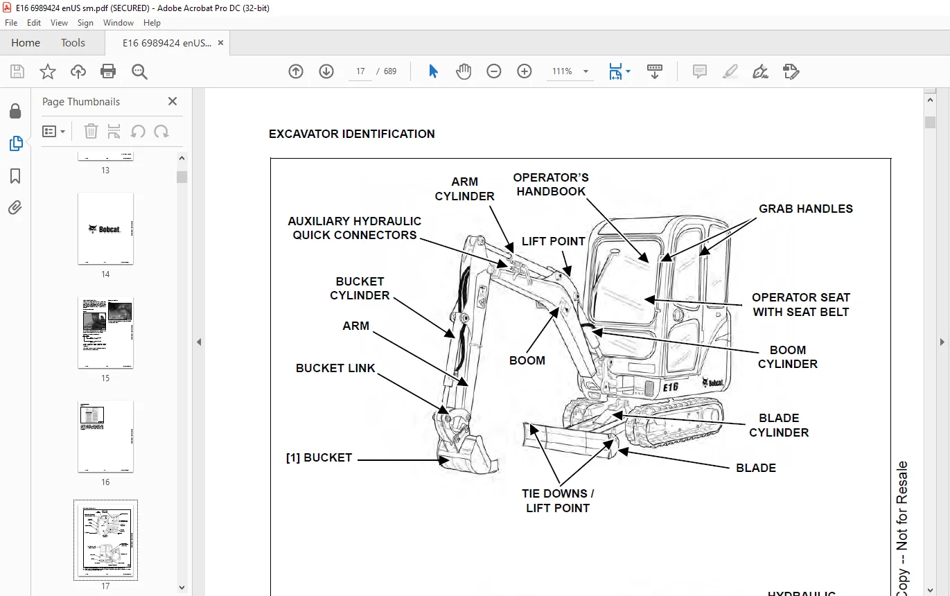
EXCAVATOR IDENTIFICATION 17
SAFETY AND MAINTENANCE 19
LIFTING AND BLOCKING THE EXCAVATOR 23
Procedure 23
UPPERSTRUCTURE SLEW LOCK 25
LIFTING THE EXCAVATOR 27
Procedure 27
OPERATOR CANOPY (ROPS / TOPS) 29
Description 29
OPERATOR CAB (ROPS / TOPS) 31
Description 31
Cab Door 32
Front Window 32
Front Wiper 34
Window Washer Reservoir 34
Right Side Windows 34
Heater 35
TRANSPORTING THE EXCAVATOR ON A TRAILER 37
Loading And Unloading 37
Fastening – Track Frame Tie Downs 38
Fastening – Upperstructure Tie Downs (Optional) 38
Fastening Arm – All Models 39
TAILGATE 41
Opening And Closing 41
Adjusting The Bumper 41
Adjusting The Latch 41
SERVICE SCHEDULE 43
Chart 43
Inspection Checkbook 44
AIR CLEANER SERVICE 45
Daily Check 45
Replacing The Filter Elements 45
CAB FILTER 47
Cleaning And Maintenance (Early Models Only) 47
ENGINE COOLING SYSTEM 49
Cleaning 49
Checking Level 49
Removing And Replacing Coolant 50
FUEL SYSTEM 53
Fuel Specifications 53
Biodiesel Blend Fuel 53
Filling The Fuel Tank 54
Fuel Filters 54
Draining The Fuel Tank 55
Removing Air From The Fuel System 55
ENGINE LUBRICATION SYSTEM 57
Checking And Adding Engine Oil 57
Engine Oil Chart 57
Removing And Replacing Oil And Filter 58
HYDRAULIC SYSTEM 59
Checking And Adding Hydraulic Fluid 59
Hydraulic / Hydrostatic Fluid Chart 60
Removing And Replacing The Hydraulic Filter 60
Removing And Replacing The Hydraulic Fluid 61
LUBRICATING THE EXCAVATOR 63
Lubrication Locations 63
TRAVEL MOTOR 67
Checking And Adding Oil 67
Removing And Replacing Oil 67
SPARK ARRESTER MUFFLER 69
Cleaning Procedure 69
ALTERNATOR BELT 71
Belt Adjustment (S/N AHLL11001 – AHLL13119) 71
Belt Adjustment (S/N AHLL13120 & Above) 72
Belt Adjustment (All Models) 73
Belt Replacement 73
SEAT BELT 75
Inspection And Maintenance 75
CONTROL CONSOLE LOCKOUTS 77
Inspection And Maintenance 77
PIVOT PINS 79
Inspection And Maintenance 79
EXCAVATOR STORAGE AND RETURN TO SERVICE 81
Storage 81
Return to Service 81
STOPPING THE ENGINE AND LEAVING THE EXCAVATOR 83
Procedure 83
EMERGENCY EXIT 85
Right Side Rear Window 85
Front Window 85
DE-AERATION 87
Procedure 87
MOTION ALARM SYSTEM 91
Description 91
Inspecting 91
Adjusting Switch Position 92
REMOTE START TOOL KIT – MEL1563 93
Remote Start Tool – MEL1563 93
Service Tool Harness Control – MEL1565 94
Service Tool Harness Communicator – MEL1566 95
REMOTE START TOOL (SERVICE TOOL) KIT – 6689779 / 7003031 97
Description 97
Remote Start Tool (Service Tool) – 6689778 / 7003030 98
Excavator Service Tool Harness – 6689747 99
Computer Service Tool Harness – 6689746 100
HYDRAULIC SYSTEM 101
HYDRAULIC/HYDROSTATIC SCHEMATICS 105
HYDRAULIC SYSTEM INFORMATION 107
Glossary Of Hydraulic / Hydrostatic Symbols 107
Troubleshooting The Hydraulic Circuit 110
Troubleshooting The Cylinder Circuit 111
Troubleshooting The Swing (Upperstructure Slew) Circuit 112
Troubleshooting The Travel Circuit 113
CYLINDER (BOOM) 115
Testing 115
Removal And Installation 116
Parts Identification 119
Disassembly 120
Assembly 122
CYLINDER (ARM) 125
Testing 125
Removal And Installation 127
Parts Identification 129
Disassembly 130
Assembly 132
CYLINDER (BOOM SWING) 135
Testing 135
Removal And Installation 136
Parts Identification 138
Disassembly 139
Assembly 141
CYLINDER (BUCKET) 145
Testing 145
Removal And Installation 146
Parts Identification 148
Disassembly 149
Assembly 151
CYLINDER (BLADE) 155
Testing 155
Removal And Installation 156
Parts Identification 158
Disassembly 159
Assembly 161
CYLINDER (TRACK FRAME EXPANSION) 165
Testing 165
Removal And Installation 166
Parts Identification 170
Disassembly 171
Assembly 173
VALVE (MAIN RELIEF) 177
Testing And Adjusting 177
VALVE (PORT RELIEF) 179
Testing And Adjusting 179
VALVE (CROSSPORT RELIEF) 181
Testing And Adjusting 181
VALVE (PRESSURE REDUCING) 183
Testing And Adjusting 183
HYDRAULIC CONTROL VALVE 185
Description 185
Removal And Installation 185
Parts Identification 188
Disassembly 189
Right Travel Valve Section Disassembly And Assembly 190
Boom Swing Valve Section Disassembly And Assembly 194
Arm Valve Section Disassembly And Assembly 197
Bucket Valve Section Disassembly And Assembly 200
Auxiliary Valve Section Disassembly And Assembly 203
Boom Valve Section Disassembly And Assembly 208
Left Travel Valve Section Disassembly And Assembly 211
Swing (Slew) Valve Section Disassembly And Assembly 215
Blade Valve Section Disassembly And Assembly 218
Assembly 222
HYDRAULIC PUMP 227
Description 227
Torque Adjustment 228
Testing The Piston Pump 229
Testing The Gear Pump 231
Testing Auxiliary Hydraulic Flow 232
Removal And Installation 233
Parts Identification 236
Disassembly 237
Gear Pump Disassembly 238
Piston Pump Disassembly 240
Piston Pump Assembly 249
Gear Pump Assembly 258
Assembly 260
MANIFOLD ASSEMBLY / ACCUMULATOR 263
Description 263
Removal And Installation 263
Parts Identification 265
Disassembly 266
Assembly 277
TRAVEL MOTOR 289
Description 289
Removal And Installation 289
Parts Identification 290
Disassembly 291
Assembly 298
SWIVEL JOINT 307
Description 307
Removal And Installation 307
Parts Identification (S/N AHll11001 to AHLL22003) 310
Parts Identification (AHLL22003 & Above) 311
Disassembly 312
Assembly 314
SWING MOTOR 317
Description 317
Removal And Installation 317
Parts Identification 318
Disassembly 319
Assembly 325
CONTROL LEVER (JOYSTICK) (RIGHT) 333
Description 333
Testing 333
Handle Removal And Installation 335
Removal And Installation 336
Parts Identification 338
Disassembly 339
Assembly 344
CONTROL LEVER (JOYSTICK) (LEFT) 349
Description 349
Testing 349
Handle Removal And Installation 351
Removal And Installation 353
Parts Identification 354
Disassembly 355
Assembly 360
HYDRAULIC FILTER MOUNT 365
Description 365
Removal And Installation 365
HYDRAULIC RESERVOIR 367
Description 367
Removal And Installation 367
OIL COOLER 369
Description 369
Removal And Installation 369
BLADE / TRACK EXPANSION SOLENOID BLOCK (FOR MODEL E16 S/N AHLL11001 – 13119) 371
Description 371
Block Removal And Installation 371
Solenoid Removal And Installation 372
Block Disassembly And Assembly 373
BLADE / TRACK EXPANSION SOLENOID BLOCK (FOR MODEL E16 S/N AHLL13120 & ABOVE) 375
Description 375
Block Removal And Installation 375
Solenoid Removal And Installation 376
Block Disassembly And Assembly 377
SLEW LOCK VALVE 379
Description 379
Removal And Installation 379
Parts Identification 381
Disassembly And Assembly 382
REMOVING AIR FROM THE HYDRAULIC SYSTEM 387
Procedure 387
UNDERCARRIAGE 389
BLADE 391
Description 391
Extension Removal And Installation 391
Blade Removal And Installation 392
TRACK UNDERCARRIAGE COMPONENTS 393
Description 393
Track Lug Height 393
Checking Tension 393
Adjusting Tension 394
Track Removal And Installation 395
Idler Removal And Installation 396
Idler Parts Identification 397
Idler Disassembly 398
Idler Assembly 399
Track Tensioner Removal And Installation 402
Track Tensioner Assembly Disassembly And Assembly 402
Roller Removal And Installation 403
Roller Parts Identification 404
Disassembly 405
Assembly 407
TRACK MAINTENANCE 409
Track Damage Identification 409
SWING CIRCLE GEAR 421
Removal And Installation 421
UPPERSTRUCTURE AND SWING SECTION 423
UPPERSTRUCTURE 427
Description 427
Removal 427
Installation 429
ROPS CANOPY 431
Removal And Installation 431
CAB 435
Removal And Installation 435
Door Removal And Installation 439
Front Window Removal And Installation 440
Right Side Rear Sliding Window Removal And Installation 443
Right Side Front Sliding Window Removal And Installation 444
Glass Removal 444
Right Side Front And Rear Sliding Window Weather Strip Removal And Installation 445
Right Side Front And Rear Sliding Window Wiper Strip Removal And Installation 445
Glass Installation 446
SEAT AND SEAT MOUNT (FOR MODEL E16 S/N AHLL11001 – 13119) 449
Seat Mount Removal And Installation 449
SEAT AND SEAT MOUNT (FOR MODEL E16 S/N AHLL13120 & ABOVE) 451
Seat Mount Removal And Installation 451
RIGHT CONSOLE 453
Description 453
Joystick Console Cover (Bottom) Removal And Installation 453
Joystick Console Cover (Top) Removal And Installation 454
Joystick Console Cover (Top) Disassembly And Assembly 455
Compression Spring Removal And Installation (Canopy Only) 456
Compression Spring Disassembly And Assembly (Canopy Only) 457
Lever Removal And Installation (Canopy Only) 458
Joystick Console Frame Removal And Installation 460
Joystick Console Frame Disassembly And Assembly 461
Right Rear Console Cover Removal And Installation 462
Right Rear Console Cover Disassembly And Assembly 463
Right Rear Console Frame Removal And Installation 464
LEFT CONSOLE 467
Description 467
Joystick Console Cover (Bottom) Removal And Installation 467
Joystick Console Cover (Top) Removal And Installation 468
Compression Spring Removal And Installation 469
Compression Spring Disassembly And Assembly 470
Lever Removal And Installation 472
Joystick Console Frame Removal And Installation 473
Joystick Console Frame Disassembly And Assembly 474
Left Rear Console Cover Removal And Installation 474
Left Rear Console Frame Removal And Installation 475
ENGINE SPEED CONTROL 477
Removal And Installation 477
Cable Removal And Installation 478
BLADE CONTROL 481
Removal And Installation 481
Disassembly And Assembly 482
Cable Removal And Installation 484
UPPERSTRUCTURE SLEW LOCK 485
Removal And Installation 485
Disassembly And Assembly 485
RIGHT PEDAL 487
Removal And Installation 487
Disassembly And Assembly 487
TRAVEL CONTROLS 489
Removal And Installation 489
Disassembly And Assembly 489
LEFT PEDAL 491
Removal And Installation 491
Disassembly And Assembly 491
CONTROL LINKAGE ASSEMBLY 493
Description 493
Removal And Installation 493
Right Half Of Control Linkage Disassembly And Assembly 495
Left Half Of Control Linkage Disassembly And Assembly 497
Bracket Of Control Linkage Disassembly And Assembly 500
FLOOR MAT AND FLOOR PANELS 501
Description 501
Removal And Installation 501
FUEL TANK 503
Removal And Installation 503
HORN 505
Removal And Installation 505
SWING FRAME 507
Description 507
Removal And Installation 507
Bushing Removal And Installation 509
Swing Frame Bushing Removal 509
Swing Frame Bushing Installation 510
Boom Pivot Bushing Removal 511
Boom Pivot Bushing Installation 511
BOOM 513
Description 513
Removal And Installation 513
Boom Bushing Removal And Installation 515
ARM 517
Description 517
Removal And Installation 517
Arm To Boom Bushing Removal And Installation 518
Arm To Bucket And Bucket Link Bushing Removal And Installation 519
BUCKET 521
Removal And Installation 521
TAILGATE 523
Removal And Installation 523
Latch Removal And Installation 524
ELECTRICAL SYSTEM AND ANALYSIS 525
ELECTRICAL SCHEMATICS 527
ELECTRICAL SYSTEM INFORMATION 528
Glossary Of Electrical Symbols 528
Troubleshooting 531
Description 532
Fuse And Relay Location / Identification 532
Fuel Timer And Diode Location / Identification 533
BATTERY 534
Maintenance 534
Removal And Installation 535
Using A Booster Battery (Jump Starting) 536
ALTERNATOR 538
Description 538
Tests 538
Alternator Output Test 539
Full Field Test 539
Alternator Regulator Test 540
Alternator Regulator Test With Voltmeter 540
Removal And Installation 541
Belt Adjustment (S/N AHLL11001 – AHLL13119) 544
Belt Adjustment (S/N AHLL13120 & Above) 545
Belt Adjustment (All Models) 546
Belt Replacement 546
Charging System Inspection 547
Parts Identification 548
STARTER 550
Removal And Installation 550
Parts Identification 553
Cleaning And Inspection 553
LIGHTS 554
Upperstructure Light Removal And Installation 554
Upperstructure Light Disassembly And Assembly 554
Boom Light Removal And Installation 555
Boom Light Disassembly And Assembly 555
Light Switch Removal And Installation 556
MICROSWITCH 558
Testing Left Console Microswitch 558
Left Console Microswitch Removal And Installation 559
Testing Right Console Microswitch 559
Right Console Microswitch Removal And Installation 561
FUEL LEVEL SENDER 562
Removal And Installation 562
Testing 562
ENGINE SERVICE 564
ENGINE INFORMATION 566
Description 566
Specifications 567
Torque Values 570
Troubleshooting 572
Engine Removal And Installation 573
Engine Mount Replacement 580
Compression – Checking 581
SPARK ARRESTER MUFFLER 582
Removal And Installation 582
AIR CLEANER 584
Removal And Installation 584
ENGINE COOLING SYSTEM 586
Radiator Removal And Installation 586
Water Pump Removal And Installation 591
Water Pump Disassembly And Assembly 591
Thermostat Removal And Installation 592
Thermostat – Checking 592
LUBRICATION SYSTEM 594
Oil Pan Removal And Installation 594
Oil Pump Removal And Installation 595
Oil Pump – Service 595
Engine Oil Pressure – Testing 596
Relief Valve 597
FUEL SYSTEM 598
Fuel Shutoff Solenoid – Checking 598
Fuel Shutoff Solenoid Removal And Installation 598
Fuel Shutoff Timer Removal And Installation 598
Fuel Injection Pump – Checking 599
Fuel Injection Pump Removal And Installation 600
Fuel Injection Pump – Timing 602
Fuel Camshaft Removal And Installation 603
Fuel Camshaft Governor 604
Fuel Injector Removal And Installation 604
Fuel Injector Nozzle Pressure – Checking 605
CYLINDER HEAD 608
Glow Plug Removal And Installation 608
Valve Clearance Adjustment 609
Valve Timing – Checking 610
Cylinder Head Removal And Installation 610
Cylinder Head Disassembly And Assembly 612
Cylinder Head – Servicing 613
Cylinder Head Top Clearance 613
Valve Guide – Checking 614
Valve And Valve Seat Reconditioning 615
Valve Seat Tightness 616
Valve Spring 617
Valve Tappets 618
Rocker Arm And Shaft – Checking 619
CRANKSHAFT AND PISTONS 620
Piston And Connecting Rod Removal And Installation 620
Piston And Connecting Rod – Servicing 621
Cylinder Bore – Checking 624
Connecting Rod Alignment 624
Crankshaft Gear Removal And Installation 625
Crankshaft And Bearings Removal And Installation 625
Crankshaft And Bearings – Servicing 627
CAMSHAFT AND TIMING GEARS 630
Timing Gearcase Cover Removal And Installation 630
Timing Gears Checking Backlash 632
Idler Gear And Camshaft Removal And Installation 632
Idler Gear And Shaft – Servicing 635
FLYWHEEL AND HOUSING 636
Flywheel Housing Removal And Installation 636
Hydraulic Pump Coupler Removal And Installation 637
Flywheel Removal 637
Flywheel Installation 638
Rear End Plate Removal And Installation 638
HEATER 640
HEATER SYSTEM 642
Description 642
Components 642
REGULAR MAINTENANCE 644
Filter Element Removal And Installation 644
Heater Coil 644
HEATER UNIT 646
Removal And Installation 646
Louver Removal And Installation 647
Threaded Insert Removal And Installation 647
HEATER COIL 648
Removal And Installation 648
HEATER FAN 652
Removal And Installation 652
HEATER VALVE 656
Removal And Installation 656
SPECIFICATIONS 658
(E16) SPECIFICATIONS 660
Machine Dimensions 660
Machine Dimensions – Standard Arm 661
Machine Dimensions – Long Arm 662
Lift Capacity (Standard Arm) 663
Lift Capacity (Long Arm) 664
Performance 665
Controls 665
Engine 666
Hydraulic System 666
Hydraulic Cylinders 667
Hydraulic Cycle Times 667
Electrical 667
Instrumentation 667
Lights 667
Drive System 667
Slew System 667
Undercarriage 668
Crawler Track Design 668
Tracks 668
Type 668
Ground Pressure 668
Capacities 668
Fuel Tank 668
Fuel Consumption 668
TECHNICAL SERVICE GUIDE SPECIFICATIONS 670
Engine 670
Engine Torques 670
Cooling System 670
Excavator Torques 670
TORQUE SPECIFICATIONS FOR BOLTS 672
Torque For General SAE Bolts 672
Torque For General Metric Bolts 673
HYDRAULIC CONNECTION SPECIFICATIONS 674
O-ring Face Seal Connection 674
Straight Thread O-ring Fitting 675
Tubelines And Hoses 675
Flare Fitting 676
Port Seal Fittings 677
HYDRAULIC FLUID SPECIFICATIONS 678
Specifications 678
CONVERSIONS 680
Decimal And Millimeter Equivalents 680
U S To Metric Conversion Chart 680
SERVICE TOOLS REQUIRED 682
Remote Start Tools 682
Hydraulic Tools 683
Engine Tools 685
HVAC Tools 687
ALPHABETICAL INDEX 688
IMAGES PREVIEW OF THE MANUAL:
Customer Support: [email protected]
https://vimeo.com/841446910?share=copy
PLEASE NOTE:
- This is the SAME MANUAL used by the dealerships to diagnose your vehicle
- No waiting for couriers / posts as this is a PDF manual and you can download it within 2 minutes time once you make the payment.
- Your payment is all safe and the delivery of the manual is INSTANT – You will be taken to the DOWNLOAD PAGE.
- So have no hesitations whatsoever and write to us about any queries you may have : heydownloadss @gmail.com
S.M