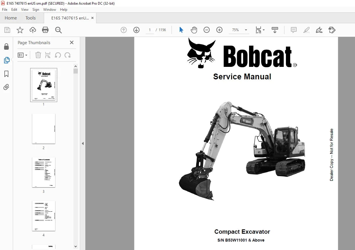
Bobcat E165 Compact Excavator Service Manual SN B53W11001 & Above – PDF DOWNLOAD
$34.95
Bobcat E165 Compact Excavator Service Manual SN B53W11001 & Above – PDF DOWNLOAD
S/N B53W11001 & Above
Description
Bobcat E165 Compact Excavator Service Manual SN B53W11001 & Above – PDF DOWNLOAD
FILE DETAILS:
Bobcat E165 Compact Excavator Service Manual SN B53W11001 & Above – PDF DOWNLOAD
Language : English
Pages :1156
Downloadable : Yes
File Type : PDF
DESCRIPTION:
S/N B53W11001 & Above
Bobcat E165 Compact Excavator Service Manual SN B53W11001 & Above – PDF DOWNLOAD
FOREWORD
This manual is for the Bobcat excavator mechanic. It provides necessary servicing and adjustment procedures for the Bobcat excavator and its component parts and systems. Refer to the Operation & Maintenance Manual for operating instructions, starting procedure, daily checks, etc.
SAFETY INSTRUCTIONS
Instructions are necessary before operating or servicing machine. Read and understand the Operation & Maintenance Manual, Operator’s Handbook and signs (decals) on machine. Follow warnings and instructions in the manuals when making repairs, adjustments or servicing. Check for correct function after adjustments, repairs or service. Untrained operators and failure to follow instructions can cause injury or death.
The following publications provide information on the safe use and maintenance of the Bobcat machine and attachments:
- The Delivery Report is used to assure that complete instructions have been given to the new owner and that the machine is in safe operating condition.
- The Operation & Maintenance Manual delivered with the machine or attachment contains operating information as well as routine maintenance and service procedures. It is a part of the machine and can be stored in a container provided on the machine. Replacement Operation & Maintenance Manuals can be ordered from your Bobcat dealer.
- Machine signs (decals) instruct on the safe operation and care of your Bobcat machine or attachment. The signs and their locations are shown in the Operation & Maintenance Manual. Replacement signs are available from your Bobcat dealer.
- An Operator’s Handbook fastened to the operator cab. It’s brief instructions are convenient to the operator. The handbook is available from your dealer in an English edition or one of many other languages. See your Bobcat dealer for more information on translated versions.
- The AEM Safety Manual delivered with the machine gives general safety information.
- The Service Manual and Parts Manual are available from your dealer for use by mechanics to do shoptype service and repair work.
IMAGES PREVIEW OF THE MANUAL:
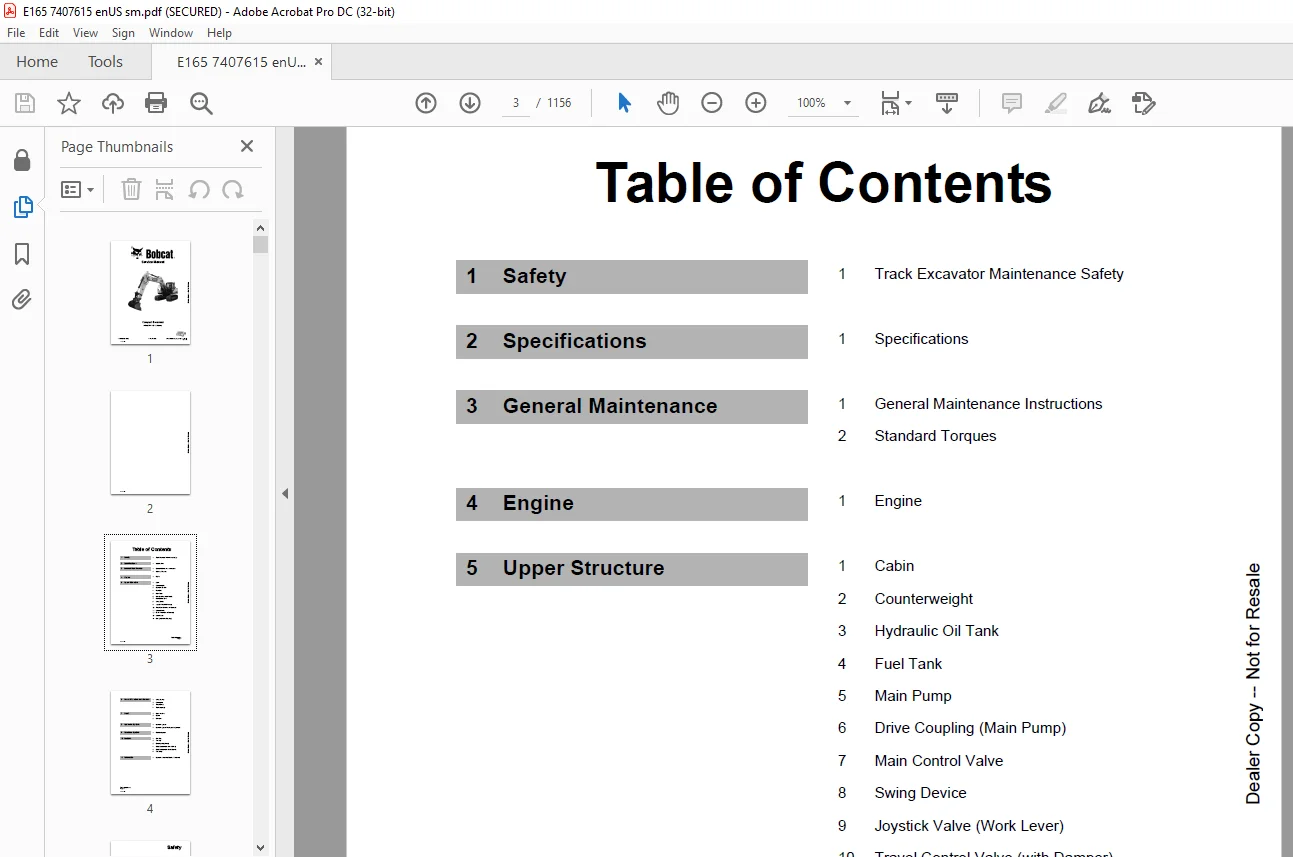
TABLE OF CONTENTS:
Bobcat E165 Compact Excavator Service Manual SN B53W11001 & Above – PDF DOWNLOAD
Table of Contents 3
Safety 5
Track Excavator Maintenance Safety 7
Safety Instructions 7
Safety Messages 9
General 11
Safe Operation is Operator’s Responsibility 11
Know Your Machine 11
Proper Work Tools and Attachments 12
Pressurized Fluids 12
Flying or Falling Objects 13
Personal Protective Equipment (PPE) 14
Correction of Machine Problems 14
Crushing and Cutting 14
Hot Coolant and Oils – Burn Prevention 15
Fire and Explosion Prevention 16
Fire Extinguisher and First-aid Kit (Emergency Medical Kit) 19
Electrical System and Electrical Shock 20
Roll-over Protective Structure (ROPS) 20
Transportation 24
Obey State and Local Over-the-Road Regulations 24
Loading and Unloading 24
Transporting Machine 25
Operation 26
Before Engine Starting 26
Work Site 27
Mounting/Dismounting 28
Cleaning 29
Operator Station 29
Seat Belt 30
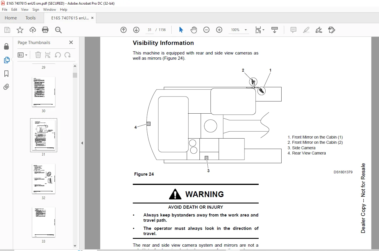
Visibility Information 31
Boost Starting or Charging Engine Batteries 33
Starting Engine 34
Swinging or Traveling 35
Lifting and Digging 37
Operation on Slopes 38
Towing 39
Attachment 40
Engine Stop 41
Parking Machine 41
Preservation/Storing Machine 42
Maintenance 44
Cleaning 46
Fire and Explosion Prevention 46
Burn Prevention 47
Lock Inspection Covers 47
Working on Machine 48
Track Tension Adjustments 49
Supports and Blocking for Work Equipment 49
High-pressure Lines, Tubes and Hoses 50
Battery 51
Environment and Circumstances 53
Work Site Areas Requiring Extra Caution 53
High-voltage Cables 54
Underground Operation 55
Working in Water 55
Working in Contaminated Environment 55
Exhaust Ventilation 56
Asbestos Information 56
Silica Dust Information 57
Disposal of Hazardous Materials 57
Sound 57
Vibration Information 58
Specifications 59
Specifications 61
Safety Instructions 61
General Description 63
Component Locations 64
Overall Dimensions 68
Working Range 70
General Specifications 72
Approximate Weight of Workload Materials 74
Performance Tests 76
Purpose of Performance Tests 76
Kinds of Tests 76
Performance Standards 76
Precautions for Evaluation of Test Data 76
Definition of “Performance Standard” 76
Preparation for Performance Tests 77
The Machine 77
Test Area 77
Precautions 77
Make Precise Measurement 77
Operational Performance Standard Table 78
Operational Performance Test 81
Hydraulic Cylinder Cycle Time 81
Travel Speed 83
Track Revolution Speed 84
Mistrack Check 85
Swing Speed 87
Swing Function Drift Check 88
Cylinder Creep 89
General Maintenance 91
General Maintenance Instructions 93
Safety Instructions 93
Welding Precautions and Instructions 95
Hydraulic System – General Precautions 97
General Precautions 98
Hydraulic System Cleanliness and Oil Leaks 99
Maintenance Precautions for Hydraulic System Service 99
Oil Leakage Precautions 100
Cleaning and Inspection 101
General Instructions 101
Bearing Inspection 102
Standard Torques 109
Safety Instructions 109
Torque Values for Standard Metric Fasteners 111
Torque Values for Standard U S Fasteners 112
Type 8 Phosphate Coated Hardware 114
Torque Values for Hose Clamps 115
ORFS Swivel Nut Recommended Torque 115
Torque Values for Split Flanges 116
Torque Wrench Extension Tools 117
Torque Multiplication 117
Other Uses for Torque Wrench Extension Tools 118
Tightening Torque Specifications (Metric) 119
Engine 123
Engine 125
Safety Instructions 125
Overview 128
General Information 129
Major Component Location 129
Engine Identification 134
Engine Lifting 136
Maintenance and Storage 138
Engine Specification 141
General Specification 141
Engine Performance Curves 142
Basic Engine 143
Cylinder Block 143
Cylinder Head 145
Valve Mechanism Cover 157
Crankcase Breather 162
Flywheel and Flywheel Housing 166
Actuating System 178
Pistons, Rings, and Connecting Rods 178
Crankshaft 193
Gears and Timing Gear Case 212
Camshaft 236
Rocker Shaft 246
Lubricant System 257
Overview 257
Engine Oil Pump 259
Engine Oil Filter 263
Engine Oil Pan 265
Engine Oil Pressure – Test 273
Excessive Bearing Wear – Inspect 273
Excessive Engine Oil Consumption – Inspect 274
Increased Engine Oil Temperature – Inspect 274
Cooling System 275
Overview 275
Water Pump 276
Water Temperature Regulator 281
Engine Oil Cooler 285
Piston Cooling Jets 291
Fuel System 293
Overview 293
High-pressure Fuel System 294
Water Separator & Pre Fuel Filter (Fuel Prefilter) 296
Main Fuel Filter 300
Fuel Injection Pump 302
Fuel Injection Lines 310
Fuel Injectors 322
Fuel System – Inspect 330
Air in Fuel – Test 331
Finding Top Center Position for No 1 Piston 333
Fuel Injection Timing – Check 334
Fuel Quality – Test 335
Fuel System – Prime 336
Cleanliness of Fuel System 337
Air Inlet and Exhaust System 339
Exhaust System 339
Clean Emissions Module (Diesel Oxidation Catalyst (DOC) and Selective Catalytic Reduction (SCR) System) 394
DEF Dosing Control System 397
Electrical System 418
Electrical Control System 418
Sensor Locations for the Engine 421
Sensor Locations for the Clean Emissions Module 426
Electronic Control Module (ECM) 426
Electric Component – Remove and Install 433
Upper Structure 463
Cabin 465
Safety Instructions 465
Cabin Identification 467
Roll-over Protective Structure (ROPS) 467
Removal 469
Installation 475
Completing work 475
Removal and Installation of Cabin Glass 476
Removal of Cabin Glass 476
Installation of Cabin Glass 478
Installation of Upper Door Glass 483
Installation of Upper Front Glass 483
Counterweight 485
Safety Instructions 485
General 487
Warning for Counterweight and Front Attachment Removal 487
Removal 489
Installation 490
Hydraulic Oil Tank 491
Safety Instructions 491
General 493
Specification 493
Air Breather 494
Removal 495
Installation 502
Completing Work 503
Fuel Tank 505
Safety Instructions 505
General 507
Specification 507
Removal 508
Installation 514
Completing Work 515
Main Pump 517
Safety Instructions 517
Axial Piston Pump 519
General Description 519
Specifications 520
Overview 522
Hydraulic Circuit 525
Tools 526
Tightening Torque 527
Removal 528
Installation 538
Completing Work 539
Disassembly 540
Reassembly 543
Troubleshooting 546
Maintenance Instructions 548
Regulator 549
Functional Explanation 549
Adjustment 556
Pilot Gear Pump 559
Specification 559
Port and Hydraulic Circuit 559
Precaution 560
Drive Coupling (Main Pump) 561
Safety Instructions 561
General 563
Specification 563
Disassembly 564
Reassembly 565
Main Control Valve 567
Safety Instructions 567
General 569
Specification 569
Overview 570
Cautions for Operation 576
Precaution 577
Removal 578
Installation 592
Completing Work 592
Disassembly 593
Cautions on Disassembly 593
Sequence of Disassembly 594
cleaning and inspection 602
Cleaning 602
Inspection 602
Reassembly 603
Caution on Assembly 603
Sequence of Reassembly 604
Troubleshooting and adjustment 614
Troubleshooting 614
Adjusting Relief Valve 616
Swing Device 619
Safety Instructions 619
General 621
Specification 621
Overview 622
Cautions for Operation 624
Precaution 627
Tools for Disassembly and Assembly 627
Tightening Torque 627
Removal 629
Installation 634
Completing work 634
Disassembly 635
Swing Motor 635
Swing Reduction Gear 640
Reassembly 644
Swing Motor 644
Swing Reduction Gear 650
Troubleshooting 658
General Instructions 658
Examination of Hydraulic Motor 658
Troubleshooting 659
Maintenance Instructions 662
Replacement Standard of Worn Parts 662
Standard of Sliding Surface Correction 662
Joystick Valve (Work Lever) 663
Safety Instructions 663
General 665
Specifications 665
Overview 666
Removal 668
Installation 674
Completing work 674
Disassembly 675
Reassembly 679
Travel Control Valve (with Damper) 687
Safety Instructions 687
General 689
Specification 689
Overview 690
Removal 691
Installation 697
Completing Work 697
Disassembly 698
Reassembly 701
Troubleshooting 706
Solenoid Valve 707
Safety Instructions 707
General 709
Specification 709
Overview 710
Disassembly and Reassembly 712
Troubleshooting 713
EPPR Valve (One or Two-way) 715
Safety Instructions 715
General 717
Specification 717
Overview 718
Hydraulic Circuit 718
Troubleshooting 719
Accumulator 721
Safety Instructions 721
General 723
Specifications 724
One Spool Valve (Rotating) 725
Safety Instructions 725
General 727
Specification 727
Overview 727
Disassembly and Assembly 728
General Cautions 728
Replacement of Spool 729
Replacement of Main Relief Valve 731
Replacement of Overload Relief Valve 733
Replacement of Sub-Block 735
Lower Structure and Chassis 737
Swing Bearing 739
Safety Instructions 739
General 741
General Description 741
Maintenance Guidelines 742
Disassembly 743
Reassembly 745
Center Joint 747
Safety Instructions 747
General 749
General Description 749
Overview 749
Removal 750
Installation 755
Completing Work 755
Disassembly 756
Reassembly 759
Troubleshooting, Testing and Adjustment 761
Inspection 761
Testing 761
Travel Device 763
Safety Instructions 763
General 765
Specification 765
Overview 766
Cautions for Operation 768
Precaution 772
Tools List for Disassembly and Reassembly 772
Removal 775
Installation 781
Completing Work 781
Disassembly 782
Preparation 782
General Precautions 782
Disassembly Procedure 783
Reassembly 796
Preparation 796
General Cautions 796
Reassembly Procedure 796
Matters to Check after Assembly 812
Performance Test 812
Troubleshooting 814
Track Assembly 817
Safety Instructions 817
General 819
Track Tension 819
Track Shoes and Links 821
Track Removal 821
Track Installation 823
Wear Limits and Tolerances 824
Sprocket 826
Wear Limits and Tolerances 826
Front Idler 827
Overview 827
Front Idler Disassembly 828
Front Idler Reassembly 829
Wear Limits and Tolerances 831
Upper Roller 832
Overview 832
Upper Roller Removal 833
Upper Roller Disassembly 833
Upper Roller Reassembly 835
Wear Limits and Tolerances 836
Lower Roller 837
Overview 837
Lower Roller Removal 837
Lower Roller Installation 838
Lower Roller Disassembly 838
Lower Roller Reassembly 839
Wear Limits and Tolerances 841
Track Adjuster 842
Disassembly 842
Assembly 843
Front 845
Boom and Arm 847
Safety Instructions 847
Specifications 849
Removal 851
Arm Removal 851
Boom Removal 853
Installation 854
Arm Installation 854
Boom Installation 854
Completing Work 854
Bucket 855
Safety Instructions 855
Bucket Tooth Inspection and Replacement 857
Bucket O-ring Replacement 858
Installation 859
Bucket Detaching and Reversal 860
Detaching 860
Reversal 860
Cylinders 861
Safety Instructions 861
General 863
General Description 863
Specification 863
Seal of Cylinder 864
Special Tools and Materials 866
Piston Nut 866
Piston Jig 867
Steel Bushing Jig 868
Dust Wiper Jig 869
Slipper Seal Jig 870
Slipper Seal Straightening Jig 871
Rod Bushing (DD-bushing) Pushing-in Jig 872
Disassembly 873
Reassembly 878
Troubleshooting 882
Hydraulic System 885
Hydraulic System 887
Safety Instructions 887
Hydraulic System 889
General Description 889
Hydraulic Schematic 890
General Description 890
Hydraulic Component and Oil Flow 892
Hydraulic Components 892
Main Oil Circuit 894
Pilot Oil Circuit 895
Return Oil Circuit 896
Safety Lever Valve Operation 897
Power Up Valve Operation 898
Swing Brake Release Operation 899
Travel Forward and Backward Operation 900
Travel High-speed Valve Operation 901
Boom Up Operation 902
Boom Down Operation 903
Easy Boom Operation 904
Arm Dump Operation 905
Arm Crowd Operation 906
Bucket Dump Operation 907
Bucket Crowd Operation 908
Combined Bucket Crowd and Boom Up Operation 909
Combined Travel and Boom, Arm, Bucket or Swing Operation 910
Two Pump Operation 911
Hydraulic System Testing and Adjustment 913
Safety Instructions 913
Procedural Troubleshooting Baseline Recommendations 915
Initial Checks and Tests to Establish Operating Condition of the Excavator 915
Pilot Pressure 917
Adjustment and Testing 917
Power Mode Valve 918
Current Signal and Hydraulic Pressure Adjustments 918
Pressure Up Valve 919
Checks and Adjustments 919
Pump Input Power Control 921
Pump Regulator Adjustment 921
Flow Meter and Flow Meter Kit Installation and Testing 924
Swing System Troubleshooting 926
Precautions/Initial Checks 926
Swing Relief Valve Checking and Adjustment 927
Electrical System 929
Electrical System 931
Safety Instructions 931
Introduction 935
Electrical Supply System 936
Engine Starting Circuit 938
Start Operation 938
After Start 940
Engine Stop 942
Charging System 944
Monitoring System 945
Instrument Panel 946
Functional Check 946
Monitoring System Schematic 948
Operation 950
Instruments 950
Warning and Indicator Lights 952
Indication of Warning Lights 952
Indication of Multifunction Gauge 955
Initial Operation 957
Graphic Information Area Display 958
Overview 958
Main Menus for the Graphic Display Area 958
Menu Selector Buttons 958
User Menu 959
User Menu – Access and Escape Methods 959
Special Menu 993
Entering/Accessing and Exiting/Escaping Menus 993
Special Menu Selections 994
Failure Code 1008
Failure Code at Machine 1008
Failure Code at Engine Side 1011
FMIs (Failure Mode Identifier) 1019
Electronic Hydraulic Control System (EPOS) 1020
Control System Schematic 1020
Power Plus Mode Control 1022
Operation 1024
Power Mode Control 1026
Smart Power Control (SPC) 1028
Operation 1028
Engine Control System 1031
Engine Control Dial 1032
Engine Control 1034
Automatic Deceleration Control (Auto Idle Control) 1036
Engine Overheat Protection System 1038
Power Boost Mode 1041
Operation 1041
Power Boost Control 1042
Automatic Travel Speed Control 1044
Automatic Travel Speed Control 1046
Water in Fuel Warning System 1047
Operation 1047
Self-diagnostic Function 1048
EPOS Controller 1048
Air Conditioner System 1050
Outline 1050
Internal and External Filters 1051
Air-Conditioning System Layout 1052
Air Conditioner/Heater Circuit Diagram 1054
Air Conditioner/Heater Unit 1056
Ambient Air Temperature Sensor 1061
Sun Sensor 1062
Control Panel 1062
Receiver Dryer 1070
Troubleshooting 1071
Refrigerant System Repairs 1073
Refrigerant Safe Handling Procedures 1073
Repair and Replacement Procedure 1074
Refrigerant Recovery 1076
Vacuuming Refrigerant System 1076
Leakage Check 1078
Refrigerant Charging 1078
Inspecting System For Leakage 1080
Wiper System 1081
Wiper Circuit 1081
Wiper Operation 1082
Lighting System 1084
Lighting System Circuit Diagram 1084
Kind of Light 1085
Operation 1085
Overload Warning Device 1086
Overload Warning Device Circuit Diagram 1086
Audio Controller 1087
Audio Controller Circuit Diagram 1087
Options 1089
One Way 1091
Safety Instructions 1091
General 1093
General Description 1093
Theory of Operation 1093
Hydraulic Circuit 1094
Caution for Installation 1095
Installation Procedure 1096
After Installation Precautions 1096
Air Bleeding 1096
Completing Work 1097
Two-way 1099
Safety Instructions 1099
General 1101
General Description 1101
Theory of Operation 1101
Structure 1102
Hydraulic Circuit 1103
Caution for Installation 1105
Installation Procedure 1106
After Installation Precautions 1106
Air Bleeding 1106
Completing Work 1107
Rotating Kit (Optional) 1109
Safety Instructions 1109
General 1111
General Description 1111
Theory of Operation 1111
Structure 1112
Hydraulic Circuit 1113
Caution for Installation 1114
Installation Procedure 1115
After Installation Precautions 1115
Air Bleeding 1115
Completing Work 1115
Quick Coupler (S/N 1011 & Below) 1117
Safety Instructions 1117
General 1119
General Description 1119
Theory of Operation 1120
Hydraulic Circuit 1121
Caution for Installation 1122
Quick Coupler Operation 1123
Securing Work Tool 1123
Attaching Quick Coupler to Excavator 1123
Releasing the Work Tool 1125
Quick Coupler (S/N 1012 & Above) 1127
Safety Instructions 1127
General 1129
General Description 1129
Theory of Operation 1130
Hydraulic Circuit 1131
Caution for Installation 1132
Quick Coupler Operation 1133
To Engage Attachment 1133
To Release Attachment 1138
Two Pump 1141
Safety Instructions 1141
General 1143
General Description 1143
Theory of Operation 1143
Hydraulic Circuit 1144
Caution for Installation 1145
Installation Procedure 1146
After Installation Precautions 1146
Air Bleeding 1146
Schematic 1147
Hydraulic Schematic / Electrical Schematic 1149
E165 Hydraulic Schematic 1151
E165 Electrical Schematic 1153
Contact us: [email protected]
https://vimeo.com/841857333?share=copy
PLEASE NOTE:
- This is the SAME exact manual used by your dealers to fix your vehicle.
- The same can be yours in the next 2-3 mins as you will be directed to the download page immediately after paying for the manual.
- Any queries / doubts regarding your purchase, please feel free to contact [email protected]
S.M