Bobcat E17Z Compact Excavator Service Manual 7314142 (07-20) – PDF DOWNLOAD
$32.95
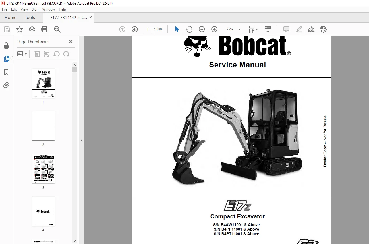
Bobcat E17Z Compact Excavator Service Manual 7314142 (07-20) – PDF DOWNLOAD
S/N B4AW11001 & Above
S/N B4PF11001 & Above
S/N B4PT11001 & Above
Description
Bobcat E17Z Compact Excavator Service Manual 7314142 (07-20) – PDF DOWNLOAD
FILE DETAILS:
Bobcat E17Z Compact Excavator Service Manual 7314142 (07-20) – PDF DOWNLOAD
Language : English
Pages : 680
Downloadable : Yes
File Type : PDF
Size:21.9 MB
DESCRIPTION:
Bobcat E17Z Compact Excavator Service Manual 7314142 (07-20) – PDF DOWNLOAD
FOREWORD:
This manual is for the Bobcat loader mechanic. It provides necessary servicing and adjustment procedures for the Bobcat loader and its component parts and systems. Refer to the Operation & Maintenance Manual for operating instructions, Starting procedure, daily checks, etc.
The following publications provide information on the safe use and maintenance of the Bobcat machine and attachments:
TABLE OF CONTENTS:
Bobcat E17Z Compact Excavator Service Manual 7314142 (07-20) – PDF DOWNLOAD
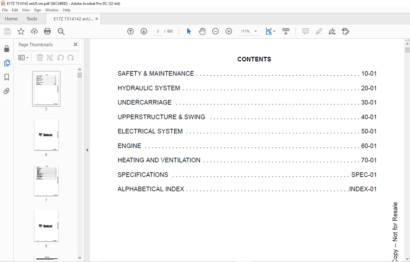
MAINTENANCE SAFETY 3
CONTENTS 5
FOREWORD 7
FOREWORD 9
SAFETY INSTRUCTIONS 11
Avoid Silica Dust 11
FIRE PREVENTION 12
Maintenance 12
Operation 12
Electrical 12
Hydraulic System 12
Fueling 12
Starting 12
Spark Arrester Exhaust System 12
Welding And Grinding 13
Fire Extinguishers 13
SERIAL NUMBER LOCATIONS 14
Excavator Serial Number 14
Engine Serial Number 14
DELIVERY REPORT 15
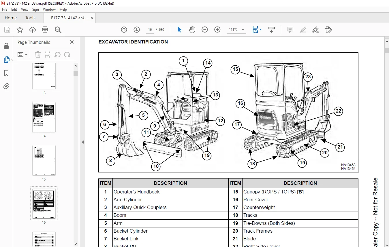
EXCAVATOR IDENTIFICATION 16
SAFETY & MAINTENANCE 17
LIFTING AND BLOCKING THE EXCAVATOR 19
Procedure 19
LIFTING THE EXCAVATOR 21
Procedure 21
OPERATOR CAB (ROPS / TOPS) 23
Description 23
OPERATOR CANOPY (ROPS / TOPS / FOPS) 25
Description 25
TRANSPORTING THE EXCAVATOR ON A TRAILER 27
Loading And Unloading 27
Fastening 27
TAILGATE 29
Opening And Closing 29
Adjusting The Latch 30
RIGHT SIDE COVER 31
Opening And Closing 31
SERVICE SCHEDULE 33
Maintenance Intervals 33
Inspection Checkbook 34
AIR CLEANER SERVICE 35
Daily Check 35
Replacing The Filters 35
ENGINE COOLING SYSTEM 37
Cleaning 37
Checking Level 38
Removing And Replacing Coolant 39
FUEL SYSTEM 41
Fuel Specifications 41
Biodiesel Blend Fuel 41
Filling The Fuel Tank 42
Fuel Filter 43
Draining The Fuel Tank 44
Removing Air From The Fuel System 45
ENGINE LUBRICATION SYSTEM 47
Checking And Adding Engine Oil 47
Engine Oil Chart 47
Removing And Replacing Oil And Filter 48
HYDRAULIC SYSTEM 49
Checking And Adding Hydraulic Oil 49
Hydraulic / Hydrostatic Fluid Chart 50
Removing And Replacing The Hydraulic Filters 50
Removing And Replacing The Hydraulic Oil 51
LUBRICATING THE EXCAVATOR 53
Lubrication Locations 53
TRAVEL MOTOR 57
Checking And Adding Oil 57
Removing And Replacing Oil 57
SPARK ARRESTER MUFFLER 59
Cleaning Procedure 59
SEAT BELT 61
Inspection And Maintenance 61
CONTROL CONSOLE LOCKOUTS 63
Inspection And Maintenance 63
PIVOT PINS 65
Inspection And Maintenance 65
TOWING THE EXCAVATOR 67
Procedure 67
EXCAVATOR STORAGE AND RETURN TO SERVICE 69
Storage 69
Return To Service 69
STOPPING THE ENGINE AND LEAVING THE EXCAVATOR 71
Procedure 71
REMOTE START TOOL KIT – MEL1563 73
Remote Start Tool – MEL1563 73
Service Tool Harness Communicator – MEL1566 75
REMOTE START TOOL (SERVICE TOOL) KIT – 7217666 77
Description 77
Remote Start Tool (Service Tool) – 7022042 78
Excavator Service Tool Harness – 6689747 79
Computer Service Tool Harness – 6689746 80
HYDRAULIC SYSTEM 81
HYDRAULIC/HYDROSTATIC SCHEMATIC 85
HYDRAULIC SYSTEM INFORMATION 88
Glossary Of Hydraulic / Hydrostatic Symbols 88
Troubleshooting The Hydraulic Circuit 91
Troubleshooting The Cylinder Circuit 92
Troubleshooting The Swing (Upperstructure Slew) Circuit 93
Troubleshooting The Travel Circuit 94
CYLINDER (BOOM) 96
Testing 96
Removal And Installation 98
Parts Identification 100
Disassembly 101
Assembly 103
CYLINDER (ARM) 106
Testing 106
Removal And Installation 108
Parts Identification 110
Disassembly 111
Assembly 113
CYLINDER (BOOM SWING) 116
Testing 116
Removal And Installation 117
Parts Identification (Earlier Models) 119
Disassembly (Earlier Models) 120
Assembly (Earlier Models) 122
Parts Identification (Later Models) 125
Disassembly (Later Models) 126
Assembly (Later Models) 128
CYLINDER (BUCKET) 132
Testing 132
Removal And Installation 134
Parts Identification 135
Disassembly 136
Assembly 138
CYLINDER (BLADE) 142
Testing 142
Removal And Installation 143
Parts Identification (Earlier Models) 145
Disassembly (Earlier Models) 146
Assembly (Earlier Models) 148
Parts Identification (Later Models) 151
Disassembly (Later Models) 152
Assembly (Later Models) 154
CYLINDER (TRACK FRAME EXPANSION) 158
Testing 158
Removal And Installation 159
Parts Identification (Earlier Models) 163
Disassembly (Earlier Models) 164
Assembly (Earlier Models) 166
Parts Identification (Later Models) 169
Disassembly (Later Models) 170
Assembly (Later Models) 172
VALVES (MAIN RELIEF) 176
Description 176
Test Conditions 178
Testing And Adjusting Main Relief At Manifold 178
Testing And Adjusting Main Relief At Hydraulic Control Valve 180
VALVES (PORT RELIEF) 182
Testing And Adjusting 182
VALVES (CROSS PORT RELIEF) 184
Testing 184
Removal And Installation 186
VALVES (PRESSURE REDUCING) 188
Testing And Adjusting 188
HYDRAULIC CONTROL VALVE 190
Description 190
Removal And Installation 190
Parts Identification 196
Disassembly 197
Assembly 203
Right And Left Travel Valve Section Disassembly And Assembly 206
Arm And Bucket Valve Section Disassembly And Assembly 210
Boom Swing And Auxiliary Valve Section Disassembly And Assembly 212
Boom Valve Section Disassembly And Assembly 216
Slew Valve Section Disassembly And Assembly 217
Blade Valve Section Disassembly And Assembly 220
HYDRAULIC PUMP 224
Description 224
Torque Adjustment 224
Testing The Piston Pump 225
Testing The Gear Pump 227
Testing Auxiliary Hydraulic Flow 228
Removal And Installation 230
Parts Identification 232
Disassembly And Assembly 233
Gear Pump Disassembly 234
Gear Pump Assembly 236
Piston Pump Disassembly 238
Piston Pump Assembly 248
MANIFOLD ASSEMBLY / ACCUMULATOR 258
Description 258
Removal And Installation 258
Parts Identification 261
ACCUMULATOR 268
Removal And Installation 268
TRAVEL MOTOR 270
Description 270
Removal And Installation 270
Parts Identification 271
Disassembly 272
Assembly 279
SWIVEL JOINT 288
Description 288
Removal And Installation 288
Parts Identification 291
Disassembly 292
Assembly 294
SWING MOTOR 298
Description 298
Removal And Installation 298
Parts Identification 300
Disassembly And Assembly 301
Motor Disassembly 302
Motor Assembly 306
Brake Carrier Disassembly And Assembly 313
CONTROL LEVER (JOYSTICK) (RIGHT) 316
Testing 316
Handle Removal And Installation 317
Joystick Assembly Removal And Installation 320
Parts Identification 323
Disassembly 324
Assembly 328
CONTROL LEVER (JOYSTICK) (LEFT) 332
Testing 332
Handle Removal And Installation 333
Joystick Assembly Removal And Installation 335
Parts Identification 336
Disassembly 337
Assembly 341
HYDRAULIC FILTER MOUNT 346
Description 346
Removal And Installation 346
HYDRAULIC RESERVOIR 348
Description 348
Removal And Installation 348
OIL COOLER 350
Removal And Installation 350
BLADE / TRACK EXPANSION SOLENOID BLOCK 352
Description 352
Block Removal And Installation 352
Solenoid Removal And Installation 354
Parts Identification 356
Block Disassembly And Assembly 357
UNDERCARRIAGE 360
BLADE 362
Description 362
Extension Removal And Installation 362
Blade Removal And Installation 363
TRACK UNDERCARRIAGE COMPONENTS 364
Description 364
Track Lug Height 364
Checking Tension 365
Adjusting Tension 366
Track Removal And Installation 367
Idler Removal And Installation 368
Track Tensioner Removal And Installation 368
Track Tensioner Disassembly And Assembly 369
Roller Removal And Installation 369
Sprocket Removal And Installation 370
Track Frame Guide Inspection 370
Removal And Installation Of Expandable Track Frame 371
TRACK MAINTENANCE 372
Track Damage Identification 372
SWING CIRCLE GEAR 384
Removal And Installation 384
UPPERSTRUCTURE & SWING 386
UPPERSTRUCTURE 390
Description 390
Removal 390
Installation 392
ROPS CANOPY 394
Removal And Installation 394
SEAT AND SEAT MOUNT 398
Removal And Installation 398
LEFT CONSOLE 400
Console Cover Removal And Installation 400
Gas Spring Removal And Installation 401
Lock Lever Removal And Installation 402
Console Removal And Installation 402
LEFT UPPERSTRUCTURE COVER 404
Removal And Installation 404
RIGHT UPPERSTRUCTURE COVER 406
Removal And Installation 406
ENGINE SPEED CONTROL 408
Removal And Installation 408
Cable Adjustment 410
BLADE CONTROL 412
Removal And Installation 412
RIGHT PEDAL (BOOM SWING) 414
Removal And Installation 414
Disassembly And Assembly 415
TRAVEL CONTROLS 416
Removal And Installation 416
Disassembly And Assembly 417
LEFT PEDAL (AUXILIARY) 420
Disassembly And Assembly 420
CONTROL LINKAGE ASSEMBLY 422
Removal And Installation 422
Disassembly And Assembly 423
FLOOR MAT AND FLOOR PANELS 426
Description 426
Removal And Installation 426
FUEL TANK 428
Removal And Installation 428
HORN 430
Removal And Installation 430
SWING FRAME 432
Description 432
Removal And Installation 432
Bushing Removal And Installation 434
Swing Frame Bushing Removal 434
Swing Frame Bushing Installation 435
BOOM 436
Description 436
Removal And Installation 436
Boom Bushing Removal And Installation 438
ARM 440
Description 440
Removal And Installation 440
Arm To Boom Bushing Removal And Installation 441
Arm To Bucket And Bucket Link Bushing Removal And Installation 442
BUCKET 444
Removal And Installation 444
TAILGATE 446
Removal And Installation 446
Latch Removal And Installation 446
COUNTERWEIGHT 448
Removal And Installation 448
OPERATOR BONNET 450
Removal And Installation 450
QUICK COUPLER (KLAC™ SYSTEM) 456
Troubleshooting 456
Daily Inspection 456
Removal And Installation 457
Parts Identification 459
Disassembly 460
Assembly 462
QUICK COUPLER (LEHNHOFF® SYSTEM) 464
Troubleshooting 464
Daily Inspection 464
Removal (MS03 And MS08) 465
Installation (MS03 And MS08) 466
Parts Identification (MS03) 467
Disassembly And Assembly (MS03) 468
Parts Identification (MS08) 469
Disassembly (MS08) 470
Assembly (MS08) 473
RIGHT SIDE COVER 478
Removal And Installation 478
CAB 480
Removal And Installation 480
Door Removal And Installation 483
Front Window Removal And Installation 484
Right Side Sliding Window Removal And Installation 487
Glass Removal 487
Glass Installation 488
ELECTRICAL SYSTEM 490
ELECTRICAL SCHEMATICS 492
ELECTRICAL SYSTEM INFORMATION 507
Glossary Of Electrical Symbols 507
Troubleshooting 510
Description 511
Fuse And Relay Location / Identification 511
BATTERY 513
Servicing 513
Removal And Installation 515
Using A Booster Battery (Jump Starting) 516
ALTERNATOR 519
Belt Adjustment 519
Belt Replacement 519
Charging System Inspection 520
Alternator Voltage Testing 521
Parts Identification 522
Removal And Installation 523
STARTER 525
Testing 525
Removal And Installation 526
Parts Identification 527
LIGHTS 529
Boom Light Removal And Installation 529
Boom Light Bulb Replacement 529
MAGNETIC LOCKOUT SENSOR 531
Removal And Installation 531
TWO-SPEED SWITCH 533
Removal And Installation 533
FUEL LEVEL SENDER 535
Removal And Installation 535
Testing 535
DIAGNOSTIC SERVICE CODES 537
Viewing Service Codes 537
Number Codes List 538
CONTROL PANEL SETUP 541
Password Setup (Keyless Start Panel) 541
Maintenance Clock 543
KEY SWITCH 545
Removal And Installation 545
MOTION ALARM SYSTEM 547
Description 547
Inspecting 547
Adjusting Switch Position 549
ENGINE 551
ENGINE INFORMATION 553
Description 553
Specifications 554
Crankshaft Re-Grind Data 558
Torque Values 559
Troubleshooting 560
Engine Removal And Installation 561
Engine Mount Replacement 566
Engine Compression – Testing 567
SPARK ARRESTER MUFFLER 569
Removal And Installation 569
AIR CLEANER 571
Removal And Installation 571
ENGINE COOLING SYSTEM 573
Radiator / Oil Cooler Removal And Installation 573
Fan Removal 575
Water Pump Removal And Installation 576
Thermostat Removal And Installation 578
Thermostat – Testing 578
LUBRICATION SYSTEM 579
Oil Pan Removal And Installation 579
Oil Pump Removal And Installation 580
Oil Pump – Service 580
Engine Oil Pressure – Testing 581
FUEL SYSTEM 583
Fuel Shutoff Solenoid Removal And Installation 583
Fuel Injection Pump – Testing 584
Fuel Injection Pump Removal And Installation 586
Fuel Injection Pump – Timing 588
Fuel Camshaft Removal And Installation 589
Fuel Camshaft Governor 590
Fuel Injector Removal And Installation 590
Fuel Injector Nozzle Pressure – Testing 591
CYLINDER HEAD 593
Glow Plug Removal And Installation 593
Valve Clearance Adjustment 594
Valve Timing – Checking 595
Cylinder Head Removal And Installation 595
Cylinder Head Disassembly And Assembly 597
Cylinder Head – Servicing 598
Cylinder Head Top Clearance 599
Valve Guide – Servicing 599
Valve And Valve Seat Reconditioning 601
Valve Spring 602
Valve Tappets 603
Rocker Arm And Shaft – Servicing 604
CRANKSHAFT AND PISTONS 605
Piston And Connecting Rod Removal And Installation 605
Piston And Connecting Rod – Servicing 607
Cylinder Bore – Measuring 609
Connecting Rod Alignment 610
Crankshaft Gear Removal And Installation 610
Crankshaft And Bearings Removal And Installation 611
Crankshaft And Bearings – Servicing 613
CAMSHAFT AND TIMING GEARS 617
Timing Gearcase Cover Removal And Installation 617
Timing Gears Measuring Backlash 619
Idler Gear And Camshaft Removal And Installation 619
Idler Gear And Shaft – Servicing 622
FLYWHEEL AND HOUSING 623
Flywheel Housing Removal And Installation 623
Hydraulic Pump Coupler Removal And Installation 624
Flywheel Removal 624
Flywheel Installation 625
Rear End Plate Removal And Installation 625
HEATING AND VENTILATION 627
HEATER SYSTEM 629
Description 629
Components 629
REGULAR MAINTENANCE 631
Filter Element Removal And Installation 631
Heater Coil 631
HEATER UNIT 633
Removal And Installation 633
HEATER COIL 635
Removal And Installation 635
HEATER FAN 639
Removal And Installation 639
HEATER VALVE 641
Removal And Installation 641
SPECIFICATIONS 643
EXCAVATOR SPECIFICATIONS 645
Machine Dimension 645
Machine Dimensions (Standard Arm) 646
Rated Lift Capacity – With Standard Arm And Canopy (With Demolition Kit) 647
Rated Lift Capacity – With Standard Arm And Cab (With Demolition Kit) 648
Rated Lift Capacity – With Standard Arm And Canopy (No Demolition Kit) 649
Rated Lift Capacity – With Standard Arm And Cab (No Demolition Kit) 650
Performance 651
Controls 651
Engine 652
Hydraulic System 652
Hydraulic Cylinders 653
Hydraulic Cycle Times 653
Electrical 653
Drive System 653
Slew System 654
Undercarriage 654
Capacities 654
Tracks 654
Ground Pressure 654
Environmental 655
TECHNICAL SERVICE GUIDE SPECIFICATIONS 657
Engine 657
Engine Torques 657
Cooling System 657
Excavator Torques 657
TORQUE SPECIFICATIONS FOR BOLTS 659
Torque For General SAE Bolts 659
Torque For General Metric Bolts 660
HYDRAULIC CONNECTION SPECIFICATIONS 661
O-ring Face Seal Connection 661
Straight Thread O-ring Fitting 662
Tubelines And Hoses 662
Flare Fitting 663
Port Seal Fitting 664
HYDRAULIC FLUID SPECIFICATIONS 665
Specifications 665
CONVERSIONS 667
Decimal And Millimeter Equivalent Chart 667
U S To Metric Conversion Chart 667
SERVICE TOOLS REQUIRED 669
Remote Start Tools 669
Hydraulic Tools 670
Engine Tools 673
Electrical Tools 675
General Tools 675
HVAC Tools 676
ALPHABETICAL INDEX 677
SERVICE SCHEDULE SYMBOLS 679
IMAGES PREVIEW OF THE MANUAL:
Questions? Email us: [email protected]
https://vimeo.com/841448014?share=copy
PLEASE NOTE:
- This is the SAME exact manual used by your dealers to fix your vehicle.
- The same can be yours in the next 2-3 mins as you will be directed to the download page immediately after paying for the manual.
- Any queries / doubts regarding your purchase, please feel free to contact [email protected]
S.M