Bobcat E17z Compact Excavator Service Manual SN B4ZM11001 & Above – PDF DOWNLOAD
$32.95
Bobcat E17z Compact Excavator Service Manual SN B4ZM11001 & Above – PDF DOWNLOAD
S/N B4ZM11001 & Above
Description
Bobcat E17z Compact Excavator Service Manual SN B4ZM11001 & Above – PDF DOWNLOAD
FILE DETAILS:
Bobcat E17z Compact Excavator Service Manual SN B4ZM11001 & Above – PDF DOWNLOAD
Language : English
Pages : 663
Downloadable : Yes
File Type : PDF
Size:20.8 MB
DESCRIPTION:
Bobcat E17z Compact Excavator Service Manual SN B4ZM11001 & Above – PDF DOWNLOAD
S/N B4ZM11001 & Above
FOREWORD
This manual is for the Bobcat excavator mechanic. It provides necessary servicing and adjustment procedures for the Bobcat excavator and its component parts and systems. Refer to the Operation & Maintenance Manual for operating instructions, starting procedure, daily checks, etc.
The following publications provide information on the safe use and maintenance of the Bobcat machine and attachments:
TABLE OF CONTENTS:
Bobcat E17z Compact Excavator Service Manual SN B4ZM11001 & Above – PDF DOWNLOAD
MAINTENANCE SAFETY 3
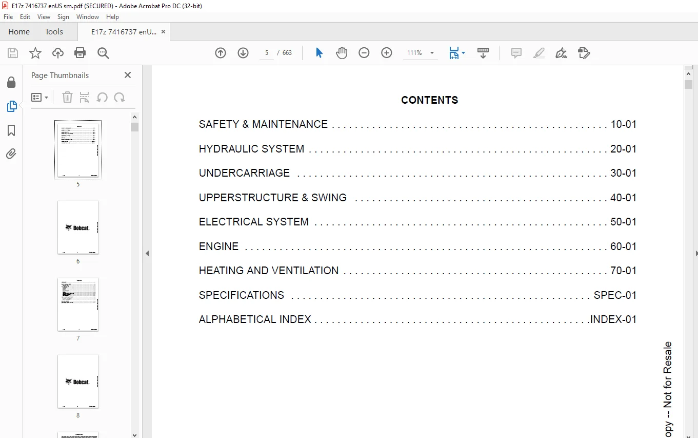
CONTENTS 5
FOREWORD 7
FOREWORD 9
SAFETY INSTRUCTIONS 11
Avoid Silica Dust 11
FIRE PREVENTION 12
Maintenance 12
Operation 12
Electrical 12
Hydraulic System 12
Fueling 12
Starting 12
Spark Arrester Exhaust System 12
Welding And Grinding 13
Fire Extinguishers 13
SERIAL NUMBER LOCATIONS 14
Excavator Serial Number 14
Engine Serial Number 14
DELIVERY REPORT 15
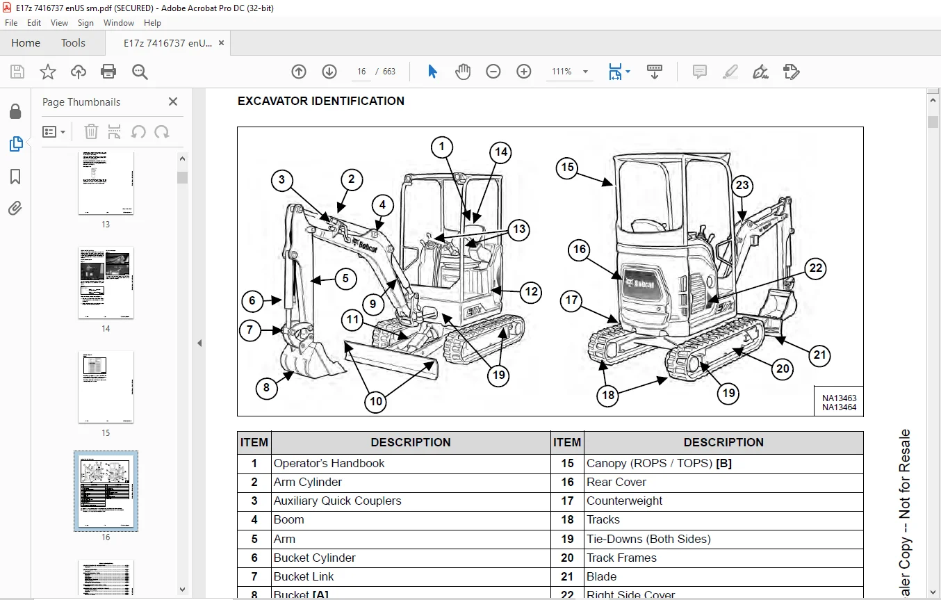
EXCAVATOR IDENTIFICATION 16
SAFETY & MAINTENANCE 17
LIFTING AND BLOCKING THE EXCAVATOR 19
Procedure 19
LIFTING THE EXCAVATOR 21
Procedure 21
OPERATOR CAB (ROPS / TOPS) 23
Description 23
Cab Door 24
Front Window 25
Front Wiper 26
Window Washer Reservoir 26
Right Side Window 27
Heating And Ventilation Ducting 27
OPERATOR CANOPY (ROPS / TOPS / FOPS) 29
Description 29
TRANSPORTING THE EXCAVATOR ON A TRAILER 31
Loading And Unloading 31
Fastening 32
TAILGATE 33
Opening And Closing 33
Adjusting the Latch 34
RIGHT SIDE COVER 35
Opening And Closing 35
SERVICE SCHEDULE 37
Maintenance Intervals 37
AIR CLEANER SERVICE 39
Daily Check 39
Replacing The Filters 39
CAB FILTER 41
Cleaning And Maintenance 41
ENGINE COOLING SYSTEM 43
Cleaning 43
Checking Coolant Level 44
Removing And Replacing Coolant 45
FUEL SYSTEM 47
Fuel Specifications 47
Biodiesel Blend Fuel 47
Filling The Fuel Tank 48
Fuel Filter 49
Draining The Fuel Tank 50
Removing Air From The Fuel System 51
ENGINE LUBRICATION SYSTEM 53
Checking And Adding Engine Oil 53
Engine Oil Chart 53
Removing And Replacing Oil And Filter 54
HYDRAULIC SYSTEM 55
Checking And Adding Hydraulic Fluid 55
Hydraulic / Hydrostatic Fluid Chart 56
Removing And Replacing The Hydraulic Filters 56
Removing And Replacing The Hydraulic Oil 57
LUBRICATING THE EXCAVATOR 59
Lubrication Locations 59
TRAVEL MOTOR 63
Checking And Adding Fluid 63
Removing And Replacing Fluid 63
SPARK ARRESTER MUFFLER 65
Cleaning Procedure 65
ALTERNATOR BELT 67
Belt Adjustment 67
Belt Replacement 67
SEAT BELT 69
Inspection And Maintenance 69
CONTROL CONSOLE LOCKOUTS 71
Inspection And Maintenance 71
PIVOT PINS 73
Inspection And Maintenance 73
TOWING THE EXCAVATOR 75
Procedure 75
EXCAVATOR STORAGE AND RETURN TO SERVICE 77
Storage 77
Return To Service 77
HYDRAULIC SYSTEM 79
HYDRAULIC / HYDROSTATIC SCHEMATICS 83
HYDRAULIC SYSTEM INFORMATION 85
Glossary Of Hydraulic / Hydrostatic Symbols 85
Troubleshooting The Hydraulic Circuit 88
Troubleshooting The Cylinder Circuit 89
Troubleshooting The Swing (Upperstructure Slew) Circuit 90
Troubleshooting The Travel Circuit 91
CYLINDER (BOOM) 93
Testing 93
Removal And Installation 95
Parts Identification 97
Disassembly 98
Assembly 100
CYLINDER (ARM) 103
Testing 103
Removal And Installation 105
Parts Identification 107
Disassembly 108
Assembly 110
CYLINDER (BOOM SWING) 113
Testing 113
Removal And Installation 114
Parts Identification 116
Disassembly 117
Assembly 119
CYLINDER (BUCKET) 123
Testing 123
Removal And Installation 125
Parts Identification 126
Disassembly 127
Assembly 129
CYLINDER (BLADE) 133
Testing 133
Removal And Installation 134
Parts Identification 136
Disassembly 137
Assembly 139
CYLINDER (TRACK FRAME EXPANSION) 143
Testing 143
Removal And Installation 144
Parts Identification 147
Disassembly 148
Assembly 150
VALVES (MAIN RELIEF) 153
Description 153
Test Conditions 155
Testing And Adjusting Main Relief At Manifold 155
Testing And Adjusting Main Relief At Hydraulic Control Valve 157
VALVES (PORT RELIEF) 159
Testing And Adjusting 159
VALVES (CROSS PORT RELIEF) 161
Testing 161
Removal And Installation 163
VALVES (PRESSURE REDUCING) 165
Testing And Adjusting 165
HYDRAULIC CONTROL VALVE 167
Description 167
Removal And Installation 167
Parts Identification 173
Disassembly 174
Assembly 180
Right And Left Travel Valve Section Disassembly And Assembly 183
Arm And Bucket Valve Section Disassembly And Assembly 187
Boom Swing And Auxiliary Valve Section Disassembly And Assembly 189
Boom Valve Section Disassembly And Assembly 193
Slew Valve Section Disassembly And Assembly 194
Blade Valve Section Disassembly And Assembly 197
HYDRAULIC PUMP 201
Description 201
Torque Adjustment 201
Testing The Piston Pump 202
Testing The Gear Pump 204
Testing Auxiliary Hydraulic Flow 205
Removal And Installation 206
Parts Identification 208
Disassembly And Assembly 209
Gear Pump Disassembly 210
Gear Pump Assembly 212
Piston Pump Disassembly 214
Piston Pump Assembly 224
MANIFOLD ASSEMBLY / ACCUMULATOR 235
Description 235
Removal And Installation 235
Parts Identification 238
ACCUMULATOR 245
Removal And Installation 245
TRAVEL MOTOR 247
Description 247
Removal And Installation 247
Parts Identification 248
Disassembly 249
Assembly 256
SWIVEL JOINT (RUBBER TRACK) 265
Description 265
Removal And Installation 265
Parts Identification 268
Disassembly 269
Assembly 272
SWIVEL JOINT (STEEL TRACK) 275
Description 275
Removal And Installation 275
Parts Identification 279
Disassembly 280
Assembly 283
SWING MOTOR 287
Description 287
Removal And Installation 287
Parts Identification 289
Disassembly And Assembly 290
Motor Disassembly 291
Motor Assembly 295
Brake Carrier Disassembly And Assembly 302
CONTROL LEVER (JOYSTICK) (RIGHT) 305
Testing 305
Handle Removal And Installation 306
Joystick Assembly Removal And Installation 309
Parts Identification 312
Disassembly 313
Assembly 317
CONTROL LEVER (JOYSTICK) (LEFT) 321
Testing 321
Handle Removal And Installation 322
Joystick Assembly Removal And Installation 324
Parts Identification 325
Disassembly 326
Assembly 330
HYDRAULIC FILTER MOUNT 335
Description 335
Removal And Installation 335
HYDRAULIC RESERVOIR 337
Description 337
Removal And Installation 337
OIL COOLER 339
Removal And Installation 339
BLADE / TRACK EXPANSION SOLENOID BLOCK 341
Description 341
Block Removal And Installation 341
Solenoid Removal And Installation 343
Parts Identification 344
Block Disassembly And Assembly 345
UNDERCARRIAGE 347
BLADE 349
Description 349
Extension Removal And Installation 349
Blade Removal And Installation 350
TRACK UNDERCARRIAGE COMPONENTS (RUBBER TRACK) 351
Description 351
Track Lug Height 351
Checking Tension 352
Adjusting Tension 353
Track Removal And Installation 354
Idler Removal And Installation 355
Track Tensioner Removal And Installation 355
Track Tensioner Disassembly And Assembly 356
Roller Removal And Installation 356
Sprocket Removal And Installation 357
Track Frame Guide Inspection 357
Removal And Installation Of Expandable Track Frame 358
TRACK UNDERCARRIAGE COMPONENTS (STEEL TRACK) 359
Description 359
Checking Tension 360
Adjusting Tension 361
Track Removal And Installation 362
Idler Removal And Installation 365
Track Tensioner Removal And Installation 365
Track Tensioner Disassembly & Assembly 366
Roller Removal And Installation 366
Sprocket Removal And Installation 367
Track Frame Guide Inspection 367
Removal And Installation Of Expandable Track Frame 368
TRACK MAINTENANCE 369
Track Damage Identification 369
SWING CIRCLE GEAR 381
Removal And Installation 381
UPPERSTRUCTURE & SWING 383
UPPERSTRUCTURE 387
Description 387
Removal 387
Installation 389
ROPS CANOPY 391
Removal And Installation 391
CAB 395
Removal And Installation 395
Door Removal And Installation 398
Front Window Removal And Installation 399
Right Side Sliding Window Removal And Installation 402
Glass Removal 402
Glass Installation 403
SEAT AND SEAT MOUNT 405
Removal And Installation 405
LEFT CONSOLE 407
Console Cover Removal And Installation 407
Gas Spring Removal And Installation 408
Lock Lever Removal And Installation 409
Console Removal And Installation 409
LEFT UPPERSTRUCTURE COVER 411
Removal And Installation 411
RIGHT UPPERSTRUCTURE COVER 413
Removal And Installation 413
ENGINE SPEED CONTROL 415
Removal And Installation 415
Cable Adjustment 417
BLADE CONTROL 419
Removal And Installation 419
RIGHT PEDAL (BOOM SWING) 421
Removal And Installation 421
Disassembly And Assembly 422
TRAVEL CONTROLS 423
Removal And Installation 423
Disassembly And Assembly 424
LEFT PEDAL (AUXILIARY) 427
Disassembly And Assembly 427
CONTROL LINKAGE ASSEMBLY 429
Removal And Installation 429
Disassembly And Assembly 430
FLOOR MAT AND FLOOR PANELS 433
Description 433
Removal And Installation 433
FUEL TANK 435
Removal And Installation 435
HORN 437
Removal And Installation 437
SWING FRAME 439
Description 439
Removal And Installation 439
Bushing Removal And Installation 441
Swing Frame Bushing Removal 441
Swing Frame Bushing Installation 442
BOOM 443
Description 443
Removal And Installation 443
Boom Bushing Removal And Installation 445
ARM 447
Description 447
Removal And Installation 447
Arm To Boom Bushing Removal And Installation 448
Arm To Bucket And Bucket Link Bushing Removal And Installation 449
BUCKET 451
Removal And Installation 451
TAILGATE 453
Removal And Installation 453
Latch Removal And Installation 453
COUNTERWEIGHT 455
Removal And Installation 455
OPERATOR BONNET 457
Removal And Installation 457
QUICK COUPLER (KLAC™ SYSTEM) 463
Troubleshooting 463
Daily Inspection 463
Removal And Installation 464
Parts Identification 466
Disassembly 467
Assembly 469
RIGHT SIDE COVER 471
Removal And Installation 471
ELECTRICAL SYSTEM 473
ELECTRICAL SCHEMATICS 475
ELECTRICAL SYSTEM INFORMATION 490
Glossary Of Electrical Symbols 490
Troubleshooting 493
Description 494
Fuse And Relay Location / Identification 494
BATTERY 496
Servicing 496
Removal And Installation 498
Using A Booster Battery (Jump Starting) 499
ALTERNATOR 502
Belt Adjustment 502
Belt Replacement 502
Charging System Inspection 503
Alternator Voltage Testing 504
Parts Identification 505
Removal And Installation 506
STARTER 508
Testing 508
Removal And Installation 509
Parts Identification 510
LIGHTS 512
Boom Light Removal And Installation 512
Boom Light Bulb Replacement 513
Cab Light Removal And Installation 513
MAGNETIC LOCKOUT SENSOR 514
Removal And Installation 514
TWO-SPEED SWITCH 516
Removal And Installation 516
FUEL LEVEL SENDER 518
Removal And Installation 518
Testing 518
DIAGNOSTIC SERVICE CODES 520
Viewing Service Codes 520
Number Codes List 521
CONTROL PANEL SETUP 524
Password Setup (Keyless Start Panel) 524
Maintenance Clock 526
KEY SWITCH 528
Removal And Installation 528
MOTION ALARM SYSTEM 530
Description 530
Inspecting 530
Adjusting Switch Position 531
WIPER MOTOR 532
Removal And Installation 532
ENGINE 534
ENGINE INFORMATION 536
Description 536
Specifications 537
Crankshaft Re-Grind Data 541
Torque Values 542
Troubleshooting 543
Engine Removal And Installation 544
Engine Mount Replacement 549
Engine Compression – Testing 550
SPARK ARRESTER MUFFLER 552
Removal And Installation 552
AIR CLEANER 554
Removal And Installation 554
ENGINE COOLING SYSTEM 556
Radiator / Oil Cooler Removal And Installation 556
Fan Removal 558
Water Pump Removal And Installation 559
Thermostat Removal And Installation 561
Thermostat – Testing 561
LUBRICATION SYSTEM 562
Oil Pan Removal And Installation 562
Oil Pump Removal And Installation 563
Oil Pump – Service 563
Engine Oil Pressure – Testing 564
FUEL SYSTEM 566
Fuel Shutoff Solenoid Removal And Installation 566
Fuel Injection Pump – Testing 567
Fuel Injection Pump Removal And Installation 569
Fuel Injection Pump – Timing 571
Fuel Camshaft Removal And Installation 572
Fuel Camshaft Governor 573
Fuel Injector Removal And Installation 573
Fuel Injector Nozzle Pressure – Testing 574
CYLINDER HEAD 576
Glow Plug Removal And Installation 576
Valve Clearance Adjustment 577
Valve Timing – Checking 578
Cylinder Head Removal And Installation 578
Cylinder Head Disassembly And Assembly 580
Cylinder Head – Servicing 581
Cylinder Head Top Clearance 582
Valve Guide – Servicing 582
Valve And Valve Seat Reconditioning 584
Valve Spring 585
Valve Tappets 586
Rocker Arm And Shaft – Servicing 587
CRANKSHAFT AND PISTONS 588
Piston And Connecting Rod Removal And Installation 588
Piston And Connecting Rod – Servicing 590
Cylinder Bore – Measuring 592
Connecting Rod Alignment 593
Crankshaft Gear Removal And Installation 593
Crankshaft And Bearings Removal And Installation 594
Crankshaft And Bearings – Servicing 596
CAMSHAFT AND TIMING GEARS 600
Timing Gearcase Cover Removal And Installation 600
Timing Gears Measuring Backlash 602
Idler Gear And Camshaft Removal And Installation 602
Idler Gear And Shaft – Servicing 605
FLYWHEEL AND HOUSING 606
Flywheel Housing Removal And Installation 606
Hydraulic Pump Coupler Removal And Installation 607
Flywheel Removal 607
Flywheel Installation 608
Rear End Plate Removal And Installation 608
HEATING AND VENTILATION 610
HEATER SYSTEM 612
Description 612
Components 612
REGULAR MAINTENANCE 614
Filter Element Removal And Installation 614
HEATER UNIT 616
Removal And Installation 616
HEATER COIL 618
Removal And Installation 618
HEATER FAN 622
Removal And Installation 622
HEATER VALVE 624
Removal And Installation 624
SPECIFICATIONS 626
EXCAVATOR SPECIFICATIONS 628
Machine Dimension 628
Machine Dimensions (Standard Arm) 629
Rated Lift Capacity – With Standard Arm And Canopy (With Demolition Kit) 630
Rated Lift Capacity – With Standard Arm And Cab (With Demolition Kit) 631
Rated Lift Capacity – With Standard Arm And Canopy (No Demolition Kit) 632
Rated Lift Capacity – With Standard Arm And Cab (No Demolition Kit) 633
Performance 634
Controls 634
Engine 635
Hydraulic System 635
Hydraulic Cylinders 636
Hydraulic Cycle Times 636
Electrical 636
Drive System 636
Slew System 637
Undercarriage 637
Capacities 637
Tracks 637
Ground Pressure 637
TECHNICAL SERVICE GUIDE SPECIFICATIONS 638
Engine 638
Engine Torques 638
Cooling System 638
Excavator Torques 638
TORQUE SPECIFICATIONS FOR BOLTS 640
Torque For General SAE Bolts 640
Torque For General Metric Bolts 641
HYDRAULIC CONNECTION SPECIFICATIONS 642
O-ring Face Seal Connection 642
Straight Thread O-ring Fitting 643
Tubelines And Hoses 643
Flare Fitting 644
Port Seal Fitting 645
HYDRAULIC FLUID SPECIFICATIONS 646
Specifications 646
CONVERSIONS 648
Decimal And Millimeter Equivalent Chart 648
U S To Metric Conversion Chart 648
SERVICE TOOLS REQUIRED 650
Remote Start Tools 650
Hydraulic Tools 651
Engine Tools 654
Electrical Tools 656
General Tools 657
HVAC Tools 658
ALPHABETICAL INDEX 660
SERVICE SCHEDULE SYMBOLS 662
IMAGES PREVIEW OF THE MANUAL:
Contact us: [email protected]
https://vimeo.com/841433916?share=copy
PLEASE NOTE:
- This is the SAME exact manual used by your dealers to fix your vehicle.
- The same can be yours in the next 2-3 mins as you will be directed to the download page immediately after paying for the manual.
- Any queries / doubts regarding your purchase, please feel free to contact [email protected]
s.m