Bobcat E19 Compact Excavator Service Manual 7255013 (07-20) – PDF DOWNLOAD
$32.95
Bobcat E19 Compact Excavator Service Manual 7255013 (07-20) – PDF DOWNLOAD
S/N AWMM11001 & Above
S/N B3LA11001 & Above
S/N B3LB11001 & Above
S/N B4PK11001 & Above
Description
Bobcat E19 Compact Excavator Service Manual 7255013 (07-20) – PDF DOWNLOAD
FILE DETAILS:
Bobcat E19 Compact Excavator Service Manual 7255013 (07-20) – PDF DOWNLOAD
Language : English
Pages : 747
Downloadable : Yes
File Type : PDF
Size:24.4 MB
DESCRIPTION:
Bobcat E19 Compact Excavator Service Manual 7255013 (07-20) – PDF DOWNLOAD
S/N AWMM11001 & Above
S/N B3LA11001 & Above
S/N B3LB11001 & Above
S/N B4PK11001 & Above
FOREWORD:
This manual is for the Bobcat loader mechanic. It provides necessary servicing and adjustment procedures for the Bobcat loader and its component parts and systems. Refer to the Operation & Maintenance Manual for operating instructions, Starting procedure, daily checks, etc.
The following publications provide information on the safe use and maintenance of the Bobcat machine and attachments:
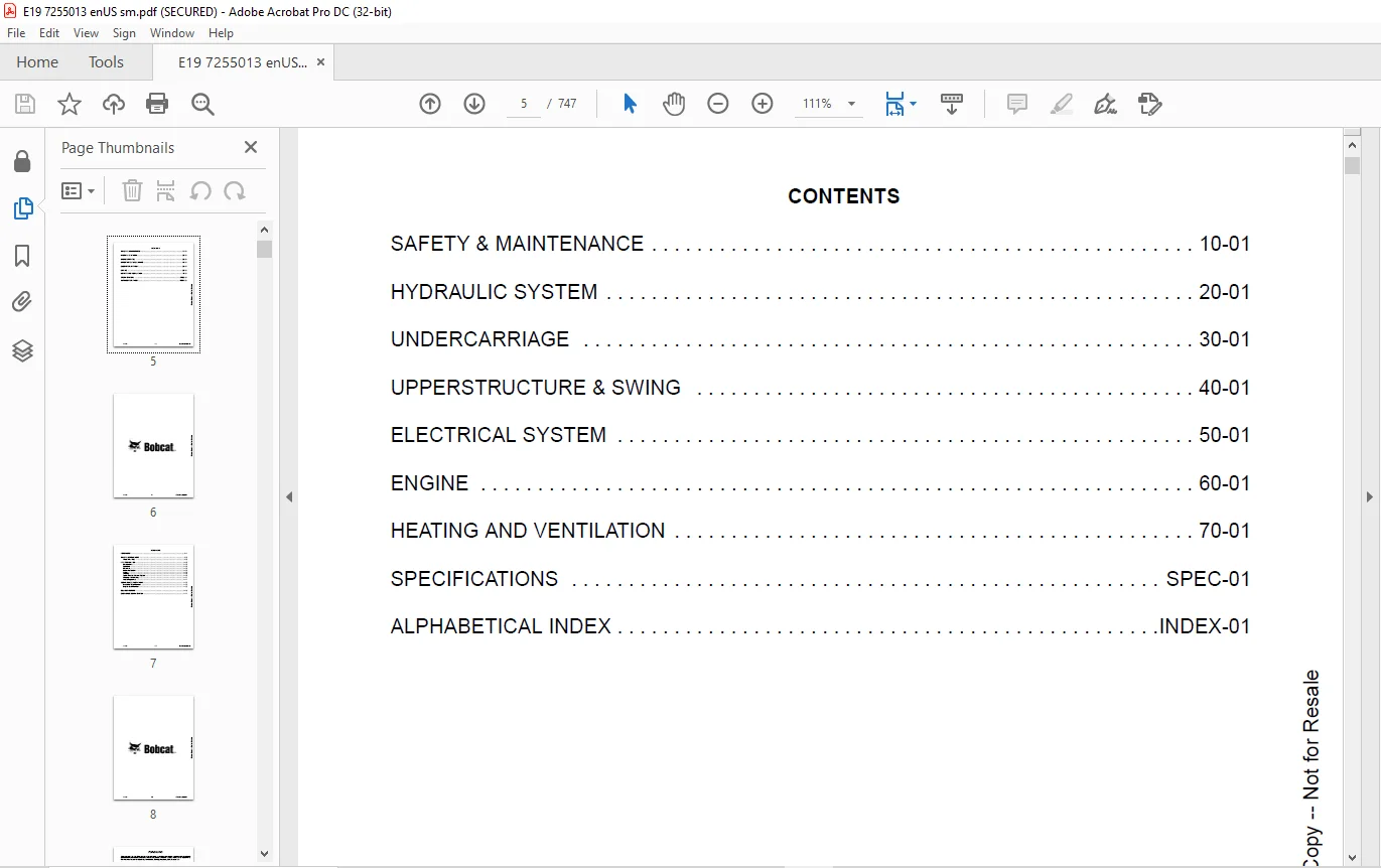
TABLE OF CONTENTS:
Bobcat E19 Compact Excavator Service Manual 7255013 (07-20) – PDF DOWNLOAD
MAINTENANCE SAFETY 3
CONTENTS 5
FOREWORD 7
FOREWORD 9
SAFETY INSTRUCTIONS 11
Avoid Silica Dust 11
FIRE PREVENTION 12
Maintenance 12
Operation 12
Electrical 12
Hydraulic System 12
Fueling 12
Starting 12
Spark Arrester Exhaust System 12
Welding And Grinding 13
Fire Extinguishers 13
SERIAL NUMBER LOCATIONS 14
Excavator Serial Number 14
Engine Serial Number 14
DELIVERY REPORT 15
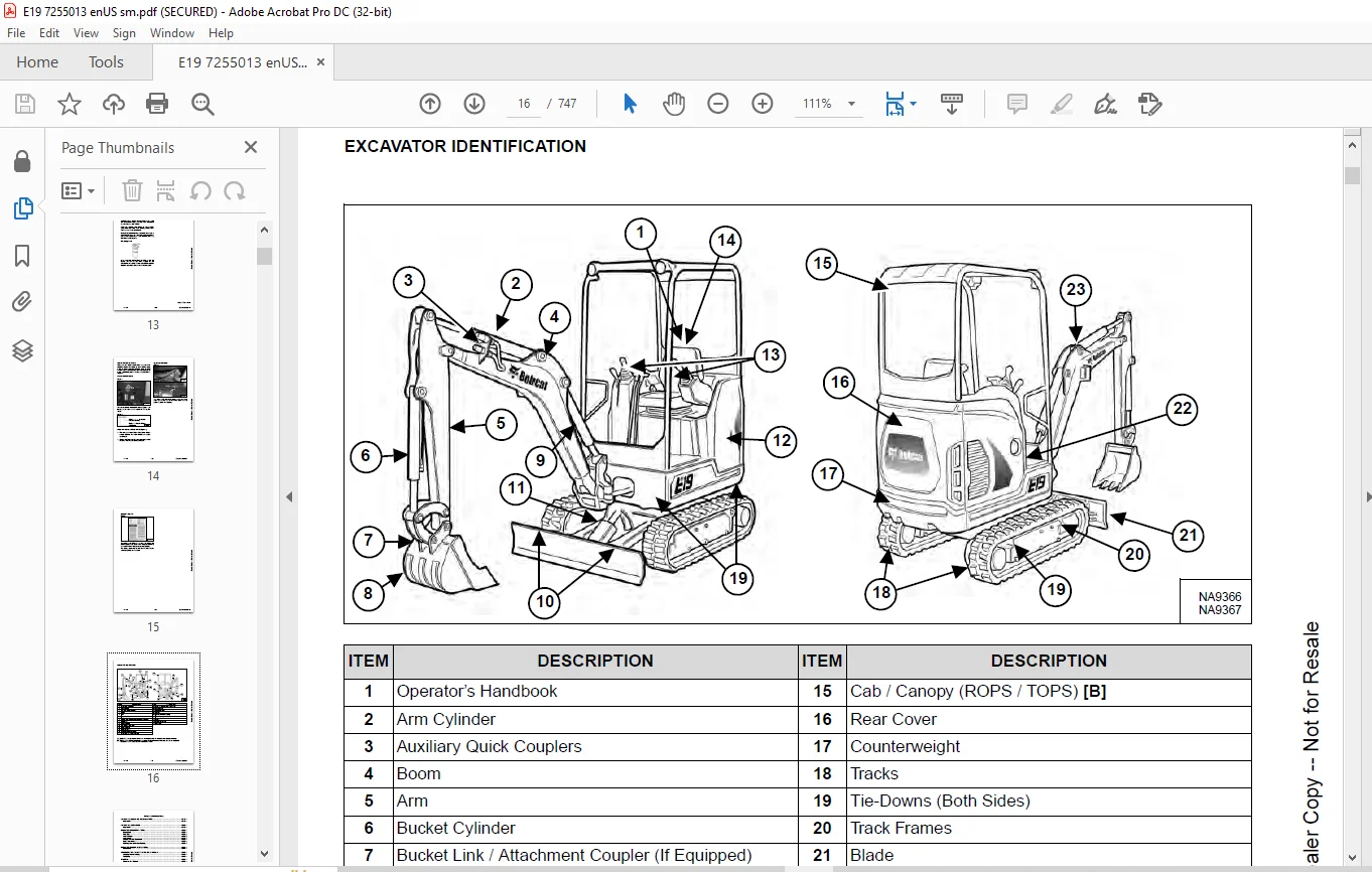
EXCAVATOR IDENTIFICATION 16
SAFETY & MAINTENANCE 17
LIFTING AND BLOCKING THE EXCAVATOR 21
Procedure 21
LIFTING THE EXCAVATOR 23
Procedure 23
OPERATOR CAB (ROPS / TOPS) 25
Description 25
Cab Door 26
Front Window 27
Front Wiper 28
Window Washer Reservoir 28
Right Side Window 29
Heating And Ventilation Ducting 29
OPERATOR CANOPY (ROPS / TOPS) 31
Description 31
TRANSPORTING THE EXCAVATOR ON A TRAILER 33
Loading And Unloading 33
Fastening 33
TAILGATE 35
Opening And Closing 35
Adjusting The Latch 36
RIGHT SIDE COVER 37
Opening And Closing Right Side Cover 37
SERVICE SCHEDULE 39
Maintenance Intervals 39
Inspection Checkbook 40
AIR CLEANER SERVICE 41
Daily Check 41
Replacing The Filter Elements 41
CAB FILTER 43
Cleaning And Maintenance 43
ENGINE COOLING SYSTEM 45
Cleaning 45
Checking Level 46
Removing And Replacing Coolant 47
FUEL SYSTEM 49
Fuel Specifications 49
Biodiesel Blend Fuel 49
Filling The Fuel Tank 50
Fuel Filter 51
Draining The Fuel Tank 52
Removing Air From The Fuel System 53
ENGINE LUBRICATION SYSTEM 55
Checking And Adding Engine Oil 55
Engine Oil Chart 55
Removing And Replacing Oil And Filter 56
HYDRAULIC SYSTEM 57
Checking And Adding Hydraulic Fluid 57
Hydraulic / Hydrostatic Fluid Chart 58
Removing And Replacing The Hydraulic Filters 58
Removing And Replacing The Hydraulic Fluid 59
LUBRICATING THE EXCAVATOR 61
Lubrication Locations 61
TRAVEL MOTOR 65
Checking And Adding Fluid 65
Removing And Replacing Fluid 65
SPARK ARRESTER MUFFLER 67
Cleaning Procedure 67
ALTERNATOR BELT 69
Belt Adjustment 69
Belt Replacement 69
SEAT BELT 71
Inspection And Maintenance 71
CONTROL CONSOLE LOCKOUTS 73
Inspection And Maintenance 73
PIVOT PINS 75
Inspection And Maintenance 75
TOWING THE EXCAVATOR 77
Procedure 77
EXCAVATOR STORAGE AND RETURN TO SERVICE 79
Storage 79
Return To Service 79
STOPPING THE ENGINE AND LEAVING THE EXCAVATOR 81
Procedure 81
EMERGENCY EXIT 83
Side Or Rear Window 83
Front Window 83
REMOTE START TOOL KIT – MEL1563 85
Remote Start Tool – MEL1563 85
Service Tool Harness Communicator – MEL1566 87
REMOTE START TOOL (SERVICE TOOL) KIT – 7217666 89
Description 89
Remote Start Tool (Service Tool) – 7022042 90
Excavator Service Tool Harness – 6689747 91
Computer Service Tool Harness – 6689746 92
HYDRAULIC SYSTEM 93
HYDRAULIC/HYDROSTATIC SCHEMATICS 97
HYDRAULIC SYSTEM INFORMATION 103
Glossary Of Hydraulic / Hydrostatic Symbols 103
Troubleshooting The Hydraulic Circuit 106
Troubleshooting The Cylinder Circuit 107
Troubleshooting The Swing (Upperstructure Slew) Circuit 108
Troubleshooting The Travel Circuit 109
CYLINDER (BOOM) 111
Testing 111
Removal And Installation 113
Parts Identification 115
Disassembly 116
Assembly 118
CYLINDER (ARM) 121
Testing 121
Removal And Installation 123
Parts Identification 125
Disassembly 126
Assembly 128
CYLINDER (BOOM SWING) 131
Testing 131
Removal And Installation 132
Parts Identification (Earlier Models) 134
Disassembly (Earlier Models) 135
Assembly (Earlier Models) 137
Parts Identification (Later Models) 140
Disassembly (Later Models) 141
Assembly (Later Models) 143
CYLINDER (BUCKET) 147
Testing 147
Removal And Installation 149
Parts Identification 150
Disassembly 151
Assembly 153
CYLINDER (BLADE) 157
Testing 157
Removal And Installation 158
Parts Identification 160
Disassembly (Earlier Models) 161
Assembly (Earlier Models) 163
Parts Identification (Later Models) 166
Disassembly (Later Models) 167
Assembly (Later Models) 169
CYLINDER (TRACK FRAME EXPANSION) 173
Testing 173
Removal And Installation 174
Parts Identification (Earlier Models) 178
Disassembly (Earlier Models) 179
Assembly (Earlier Models) 181
Parts Identification (Later Models) 184
Disassembly (Later Models) 185
Assembly (Later Models) 187
VALVE (MAIN RELIEF) 191
Description 191
Test Conditions 193
Testing And Adjusting Main Relief At Manifold 194
Testing And Adjusting Main Relief At Hydraulic Control Valve 195
VALVE (PORT RELIEF) 197
Testing And Adjusting 197
VALVE (CROSS PORT RELIEF) 199
Testing 199
Removal And Installation 202
VALVE (PRESSURE REDUCING) 203
Testing And Adjusting 203
HYDRAULIC CONTROL VALVE 205
Description 205
Removal And Installation 205
Parts Identification 211
Disassembly 212
Assembly 218
Right And Left Travel Valve Section Disassembly And Assembly 221
Arm And Bucket Valve Section Disassembly And Assembly 225
Boom Swing And Auxiliary Valve Section Disassembly And Assembly 227
Boom Valve Section Disassembly And Assembly 231
Slew Valve Section Disassembly And Assembly 232
Blade Valve Section Disassembly And Assembly 235
HYDRAULIC PUMP 239
Description 239
Torque Adjustment 239
Testing The Piston Pump 240
Testing The Gear Pump 242
Testing Auxiliary Hydraulic Flow 243
Removal And Installation 245
Parts Identification 247
Disassembly And Assembly 248
Gear Pump Disassembly 249
Gear Pump Assembly 251
Piston Pump Disassembly 253
Piston Pump Assembly 263
MANIFOLD ASSEMBLY / ACCUMULATOR 273
Description 273
Removal And Installation 273
Parts Identification 276
ACCUMULATOR 283
Removal And Installation 283
TRAVEL MOTOR (SINGLE SPEED) 285
Description 285
Removal And Installation 285
Parts Identification 286
Disassembly 287
Assembly 294
TRAVEL MOTOR (TWO SPEED) 303
Description 303
Removal And Installation 303
Parts Identification 304
Disassembly 305
Assembly 312
SWIVEL JOINT 321
Description 321
Removal And Installation 321
Parts Identification 324
Disassembly 325
Assembly 327
SWING MOTOR 331
Description 331
Removal And Installation 331
Parts Identification 333
Motor Disassembly 334
Motor Assembly 339
Brake Carrier Disassembly And Assembly 346
CONTROL LEVER (JOYSTICK) (RIGHT) 349
Testing 349
Handle Removal And Installation 350
Joystick Assembly Removal And Installation 352
Parts Identification 355
Disassembly 356
Assembly 360
CONTROL LEVER (JOYSTICK) (LEFT) 365
Testing 365
Handle Removal And Installation 366
Joystick Assembly Removal And Installation 368
Parts Identification 369
Disassembly 370
Assembly 374
HYDRAULIC FILTER MOUNT 379
Description 379
Removal And Installation 379
HYDRAULIC RESERVOIR 381
Description 381
Removal And Installation 381
OIL COOLER 383
Removal And Installation 383
BLADE / TRACK EXPANSION SOLENOID BLOCK 385
Description 385
Block Removal And Installation 385
Solenoid Removal And Installation 387
Parts Identification 388
Block Disassembly And Assembly 389
UNDERCARRIAGE 391
BLADE 393
Description 393
Extension Removal And Installation 393
Blade Removal And Installation 394
TRACK UNDERCARRIAGE COMPONENTS 395
Description 395
Track Lug Height 395
Checking Tension 396
Adjusting Tension 397
Track Removal And Installation 399
Idler Removal And Installation 400
Track Tensioner Removal And Installation 400
Track Tensioner Disassembly & Assembly 401
Roller Removal And Installation 402
Sprocket Removal And Installation 402
Removal And Installation Of Expandable Track Frame 404
TRACK MAINTENANCE 405
Track Damage Identification 405
SWING CIRCLE GEAR 417
Removal And Installation 417
UPPERSTRUCTURE & SWING 419
UPPERSTRUCTURE 423
Description 423
Removal 423
Installation 425
ROPS CANOPY 427
Removal And Installation 427
CAB 431
Removal And Installation 431
Door Removal And Installation 435
Front Window Removal And Installation 436
Right Side Sliding Window Removal And Installation 439
Glass Removal 439
Glass Installation 440
SEAT AND SEAT MOUNT 443
Removal And Installation 443
LEFT CONSOLE 445
Console Cover Removal And Installation 445
Gas Spring Removal And Installation 446
Lock Lever Removal And Installation 447
Console Removal And Installation 448
LEFT UPPERSTRUCTURE COVER 449
Removal And Installation 449
RIGHT UPPERSTRUCTURE COVER 451
Removal And Installation 451
ENGINE SPEED CONTROL 453
Removal And Installation 453
Cable Adjustment 456
BLADE CONTROL 457
Removal And Installation 457
RIGHT PEDAL (BOOM SWING) 459
Removal And Installation 459
Disassembly And Assembly 460
TRAVEL CONTROLS 461
Removal And Installation 461
Disassembly And Assembly 462
LEFT PEDAL (AUXILIARY) 465
Disassembly And Assembly 465
CONTROL LINKAGE ASSEMBLY 467
Removal And Installation 467
Disassembly And Assembly 468
FLOOR MAT AND FLOOR PANELS 471
Description 471
Removal And Installation 471
FUEL TANK 473
Removal And Installation 473
HORN 475
Removal And Installation 475
SWING FRAME 477
Description 477
Removal And Installation 477
Bushing Removal And Installation 479
Swing Frame Bushing Removal 479
Swing Frame Bushing Installation 480
BOOM 481
Description 481
Removal And Installation 481
Boom Bushing Removal And Installation 483
ARM 485
Description 485
Removal And Installation 485
Arm To Boom Bushing Removal And Installation 486
Arm To Bucket And Bucket Link Bushing Removal And Installation 487
BUCKET 489
Removal And Installation 489
TAILGATE 491
Removal And Installation 491
Latch Removal And Installation 492
COUNTERWEIGHT 493
Removal And Installation 493
OPERATOR HOOD 495
Removal And Installation 495
QUICK COUPLER (KLAC™ SYSTEM) 501
Troubleshooting 501
Daily Inspection 501
Removal And Installation 502
Parts Identification 504
Disassembly 505
Assembly 507
QUICK COUPLER (LEHNHOFF® SYSTEM) 509
Troubleshooting 509
Daily Inspection 509
Removal (MS03 And MS08) 510
Installation (MS03 And MS08) 511
Parts Identification (MS03) 512
Disassembly And Assembly (MS03) 513
Parts Identification (MS08) 514
Disassembly (MS08) 515
Assembly (MS08) 518
RIGHT SIDE COVER 523
Removal And Installation 523
TOOL BOX 525
Removal And Installation 525
ELECTRICAL SYSTEM 527
ELECTRICAL SCHEMATICS 529
ELECTRICAL SYSTEM INFORMATION 558
Glossary Of Electrical Symbols 558
Troubleshooting 561
Description 562
Fuse And Relay Location / Identification 562
BATTERY 564
Location 564
Servicing 564
Maintaining Battery Charge Level 565
Battery Service During Machine Storage 565
Battery Testing 565
Battery Charging 566
Using a Booster Battery (Jump Starting) 566
Removing And Installing The Battery 568
ALTERNATOR 570
Belt Adjustment 570
Belt Replacement 570
Charging System Inspection 571
Alternator Voltage Testing 572
Removal And Installation 573
Parts Identification 574
STARTER 576
Testing 576
Removal And Installation 577
Parts Identification 578
LIGHTS 580
Boom Light Removal And Installation 580
Boom Light Bulb Replacement 580
Cab Light Removal And Installation 581
Cab Light Bulb Replacement 581
MAGNETIC LOCKOUT SENSOR 582
Removal And Installation 582
TWO-SPEED SWITCH 584
Removal And Installation 584
FUEL LEVEL SENDER 586
Removal And Installation 586
Testing 586
DIAGNOSTIC SERVICE CODES 588
Viewing Service Codes 588
Number Codes List (S/N B3LA11001 & Above And B3LB11001 & Above) 589
Number Codes List (S/N AWMM11001 & Above And B4PK11001 & Above) 591
CONTROL PANEL SETUP 594
Password Setup (Keyless Start Panel) 594
Password Lockout Feature 595
Password Setup (Deluxe Instrument Panel) 595
Maintenance Clock 599
Standard Instrument Panel 599
Reset 599
KEY SWITCH 600
Removal And Installation 600
WIPER MOTOR 602
Removal And Installation 602
MOTION ALARM SYSTEM 604
Description 604
Inspecting 604
Adjusting Switch Position 605
ENGINE 606
ENGINE INFORMATION 608
Description 608
Specifications 609
Crankshaft Re-Grind Data 613
Torque Values 614
Troubleshooting 615
Engine Removal And Installation 616
Engine Mount Replacement 622
Engine Compression – Testing 623
SPARK ARRESTER MUFFLER 624
Removal And Installation 624
AIR CLEANER 626
Removal And Installation 626
ENGINE COOLING SYSTEM 628
Radiator / Oil Cooler Removal And Installation 628
Fan Removal 630
Water Pump Removal And Installation 631
Thermostat Removal And Installation 632
Thermostat – Testing 632
LUBRICATION SYSTEM 634
Oil Pan Removal And Installation 634
Oil Pump Removal And Installation 635
Oil Pump – Service 635
Engine Oil Pressure – Testing 636
FUEL SYSTEM 638
Fuel Shutoff Solenoid Removal And Installation 638
Fuel Injection Pump – Testing 639
Fuel Injection Pump Removal And Installation 641
Fuel Injection Pump – Timing 643
Fuel Camshaft Removal And Installation 644
Fuel Camshaft Governor 645
Fuel Injector Removal And Installation 645
Fuel Injector Nozzle Pressure – Testing 646
CYLINDER HEAD 648
Glow Plug Removal And Installation 648
Valve Clearance Adjustment 649
Valve Timing – Checking 650
Cylinder Head Removal And Installation 650
Cylinder Head Disassembly And Assembly 652
Cylinder Head – Servicing 653
Cylinder Head Top Clearance 654
Valve Guide – Servicing 654
Valve And Valve Seat Reconditioning 656
Valve Spring 657
Valve Tappets 658
Rocker Arm And Shaft – Servicing 659
CRANKSHAFT AND PISTONS 660
Piston And Connecting Rod Removal And Installation 660
Piston And Connecting Rod Disassembly And Assembly 661
Piston And Connecting Rod – Servicing 662
Cylinder Bore – Measuring 664
Connecting Rod Alignment 665
Crankshaft Gear Removal And Installation 665
Crankshaft And Bearings Removal And Installation 666
Crankshaft And Bearings – Servicing 668
CAMSHAFT AND TIMING GEARS 672
Timing Gearcase Cover Removal And Installation 672
Timing Gears Measuring Backlash 674
Idler Gear And Camshaft Removal And Installation 674
Idler Gear And Shaft – Servicing 677
FLYWHEEL AND HOUSING 678
Flywheel Housing Removal And Installation 678
Hydraulic Pump Coupler Removal And Installation 679
Flywheel Removal 679
Flywheel Installation 680
Rear End Plate Removal And Installation 680
HEATING AND VENTILATION 682
HEATER SYSTEM 684
Description 684
Components 684
REGULAR MAINTENANCE 686
Filter Element Removal And Installation 686
Heater Coil 686
HEATER UNIT 688
Removal And Installation 688
HEATER COIL 690
Removal And Installation 690
HEATER FAN 694
Removal And Installation 694
HEATER VALVE 696
Removal And Installation 696
SPECIFICATIONS 698
EXCAVATOR SPECIFICATIONS 700
Machine Dimensions 700
Machine Dimensions (Standard Arm) 701
Machine Dimensions (Long Arm) 702
Rated Lift Capacity – With Standard Arm And Canopy (No Demolition Kit) 703
Rated Lift Capacity – With Standard Arm And Canopy (With Demolition Kit) 704
Rated Lift Capacity – With Standard Arm, Optional Counterweight And Canopy (No Demolition Kit) 705
Rated Lift Capacity – With Standard Arm, Optional Counterweight And Canopy (With Demolition Kit) 706
Rated Lift Capacity – With Standard Arm And Cab (No Demolition Kit) 707
Rated Lift Capacity – With Standard Arm And Cab (With Demolition Kit) 708
Rated Lift Capacity – With Standard Arm, Optional Counterweight And Cab (No Demolition Kit) 709
Rated Lift Capacity – With Standard Arm, Optional Counterweight And Cab (With Demolition Kit) 710
Rated Lift Capacity – With Long Arm And Canopy (No Demolition Kit) 711
Rated Lift Capacity – With Long Arm And Canopy (With Demolition Kit) 712
Rated Lift Capacity – With Long Arm, Optional Counterweight And Canopy (No Demolition Kit) 713
Rated Lift Capacity – With Long Arm, Optional Counterweight And Canopy (With Demolition Kit) 714
Rated Lift Capacity – With Long Arm And Cab (No Demolition Kit) 715
Rated Lift Capacity – With Long Arm And Cab (With Demolition Kit) 716
Rated Lift Capacity – With Long Arm, Optional Counterweight And Cab (No Demolition Kit) 717
Rated Lift Capacity – With Long Arm, Optional Counterweight And Cab (With Demolition Kit) 718
Performance 719
Controls 719
Engine 720
Hydraulic System 720
Hydraulic Cylinders 721
Hydraulic Cycle Times 721
Electrical 721
Drive System 721
Slew System 722
Undercarriage 722
Capacities 722
Tracks 722
Ground Pressure 722
Environmental 723
Temperature Range 723
TECHNICAL SERVICE GUIDE SPECIFICATIONS 724
Engine 724
Engine Torques 724
Cooling System 724
Excavator Torques 724
TORQUE SPECIFICATIONS FOR BOLTS 726
Torque For General SAE Bolts 726
Torque For General Metric Bolts 727
HYDRAULIC CONNECTION SPECIFICATIONS 728
O-ring Face Seal Connection 728
Straight Thread O-ring Fitting 729
Tubelines And Hoses 729
Flare Fitting 730
Port Seal Fitting 731
HYDRAULIC FLUID SPECIFICATIONS 732
Specifications 732
CONVERSIONS 734
Decimal And Millimeter Equivalent Chart 734
U S To Metric Conversion Chart 734
SERVICE TOOLS REQUIRED 736
Remote Start Tools 736
Hydraulic Tools 737
Engine Tools 740
Electrical Tools 742
General Tools 742
HVAC Tools 743
ALPHABETICAL INDEX 744
SERVICE SCHEDULE SYMBOLS 746
IMAGES PREVIEW OF THE MANUAL:
Contact us: [email protected]
https://vimeo.com/841451258?share=copy
PLEASE NOTE:
- This is the SAME exact manual used by your dealers to fix your vehicle.
- The same can be yours in the next 2-3 mins as you will be directed to the download page immediately after paying for the manual.
- Any queries / doubts regarding your purchase, please feel free to contact [email protected]
s.m