Bobcat E20 Compact Excavator Service Manual 7255008 (07-20) – PDF DOWNLOAD
$31.95
Bobcat E20 Compact Excavator Service Manual 7255008 (07-20) – PDF DOWNLOAD
S/N AWRH11001 & Above
S/N B3BL11001 & Above
Description
Bobcat E20 Compact Excavator Service Manual 7255008 (07-20) – PDF DOWNLOAD
FILE DETAILS:
Bobcat E20 Compact Excavator Service Manual 7255008 (07-20) – PDF DOWNLOAD
Language : English
Pages : 691
Downloadable : Yes
File Type : PDF
Size:22.3 MB
DESCRIPTION:
Bobcat E20 Compact Excavator Service Manual 7255008 (07-20) – PDF DOWNLOAD
S/N AWRH11001 & Above
S/N B3BL11001 & Above
FOREWORD:
This manual is for the Bobcat loader mechanic. It provides necessary servicing and adjustment procedures for the Bobcat loader and its component parts and systems. Refer to the Operation & Maintenance Manual for operating instructions, Starting procedure, daily checks, etc.
The following publications provide information on the safe use and maintenance of the Bobcat machine and attachments:
TABLE OF CONTENTS:
Bobcat E20 Compact Excavator Service Manual 7255008 (07-20) – PDF DOWNLOAD
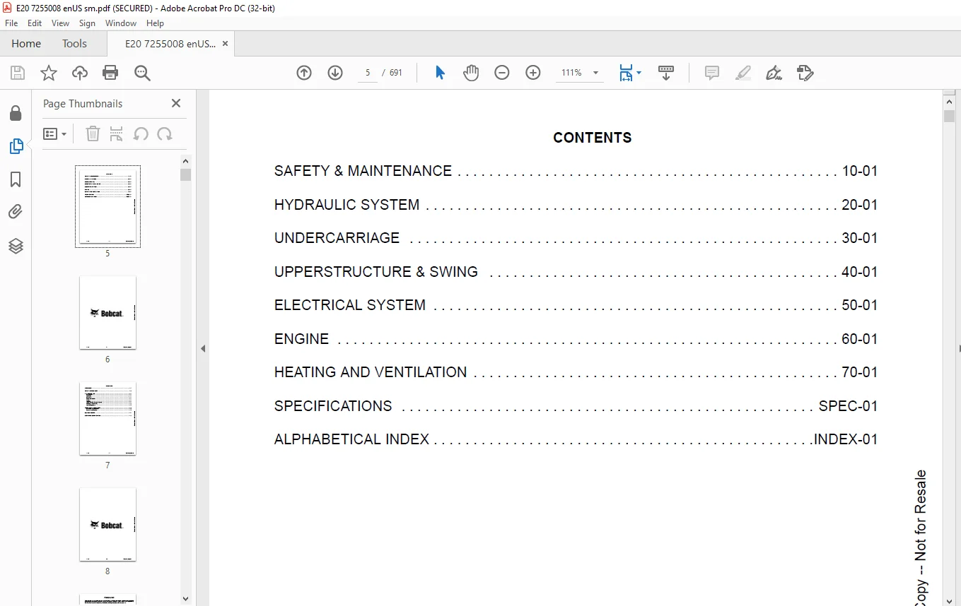
MAINTENANCE SAFETY 3
CONTENTS 5
FOREWORD 7
FOREWORD 9
SAFETY INSTRUCTIONS 11
FIRE PREVENTION 13
Maintenance 13
Operation 13
Electrical 13
Hydraulic System 13
Fueling 13
Starting 13
Spark Arrester Exhaust System 13
Welding And Grinding 14
Fire Extinguishers 14
SERIAL NUMBER LOCATIONS 15
Excavator Serial Number 15
Engine Serial Number 15
DELIVERY REPORT 16
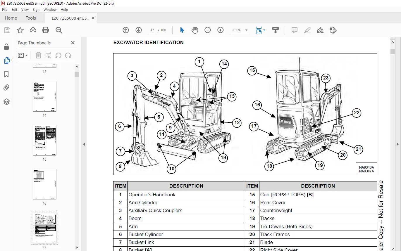
EXCAVATOR IDENTIFICATION 17
SAFETY & MAINTENANCE 19
LIFTING AND BLOCKING THE EXCAVATOR 23
Procedure 23
LIFTING THE EXCAVATOR 25
Procedure 25
OPERATOR CAB (ROPS / TOPS) 27
Description 27
Cab Door 28
Front Window 29
Front Wiper 30
Window Washer Reservoir 30
Right Side Window 31
Heating And Ventilation Ducting 31
OPERATOR CANOPY (ROPS / TOPS) 33
Description 33
TRANSPORTING THE EXCAVATOR ON A TRAILER 35
Loading And Unloading 35
Fastening 35
TAILGATE 37
Opening And Closing 37
Adjusting The Latch 38
Opening And Closing Right Side Cover 38
SERVICE SCHEDULE 39
Maintenance Intervals 39
AIR CLEANER SERVICE 41
Daily Check 41
Replacing The Filter Elements 41
CAB FILTER 43
Cleaning And Maintenance 43
ENGINE COOLING SYSTEM 45
Cleaning 45
Checking Level 46
Removing And Replacing Coolant 47
FUEL SYSTEM 49
Fuel Specifications 49
Biodiesel Blend Fuel 49
Filling The Fuel Tank 50
Fuel Filter 51
Draining The Fuel Tank 52
Removing Air From The Fuel System 53
ENGINE LUBRICATION SYSTEM 55
Checking And Adding Engine Oil 55
Engine Oil Chart 55
Removing And Replacing Oil And Filter 56
HYDRAULIC SYSTEM 57
Checking And Adding Hydraulic Oil 57
Hydraulic / Hydrostatic Fluid Chart 58
Removing And Replacing The Hydraulic Filters 58
Removing And Replacing The Hydraulic Oil 59
LUBRICATING THE EXCAVATOR 61
Lubrication Locations 61
TRAVEL MOTOR 65
Checking And Adding Oil 65
Removing And Replacing Oil 65
SPARK ARRESTER MUFFLER 67
Cleaning Procedure 67
ALTERNATOR BELT 69
Belt Adjustment 69
Belt Replacement 69
SEAT BELT 71
Inspection And Maintenance 71
CONTROL CONSOLE LOCKOUTS 73
Inspection And Maintenance 73
PIVOT PINS 75
Inspection And Maintenance 75
EXCAVATOR STORAGE AND RETURN TO SERVICE 77
Storage 77
Return To Service 77
STOPPING THE ENGINE AND LEAVING THE EXCAVATOR 79
Procedure 79
EMERGENCY EXIT 81
Rear Window 81
Front Window 81
REMOTE START TOOL KIT – MEL1563 83
Remote Start Tool – MEL1563 83
Service Tool Harness Communicator – MEL1566 85
REMOTE START TOOL (SERVICE TOOL) KIT – 7217666 87
Description 87
Remote Start Tool (Service Tool) – 7022042 88
Excavator Service Tool Harness – 6689747 89
Computer Service Tool Harness – 6689746 90
HYDRAULIC SYSTEM 91
HYDRAULIC / HYDROSTATIC SCHEMATICS 95
HYDRAULIC SYSTEM INFORMATION 101
Glossary Of Hydraulic / Hydrostatic Symbols 101
Troubleshooting The Hydraulic Circuit 104
Troubleshooting The Cylinder Circuit 105
Troubleshooting The Swing (Upperstructure Slew) Circuit 106
Troubleshooting The Travel Circuit 107
CYLINDER (BOOM) 109
Testing 109
Removal And Installation 111
Parts Identification 113
Disassembly 114
Assembly 116
CYLINDER (ARM) 119
Testing 119
Removal And Installation 121
Parts Identification 123
Disassembly 124
Assembly 126
CYLINDER (BOOM SWING) 129
Testing 129
Removal And Installation 130
Parts Identification (Earlier Models) 132
Disassembly (Earlier Models) 133
Assembly (Earlier Models) 135
Parts Identification (Later Models) 138
Disassembly (Later Models) 139
Assembly (Later Models) 141
CYLINDER (BUCKET) 145
Testing 145
Removal And Installation 147
Parts Identification 148
Disassembly 149
Assembly 151
CYLINDER (BLADE) 155
Testing 155
Removal And Installation 156
Parts Identification (Earlier Models) 158
Disassembly (Earlier Models) 159
Assembly (Earlier Models) 161
Parts Identification (Later Models) 164
Disassembly (Later Models) 165
Assembly (Later Models) 167
CYLINDER (TRACK FRAME EXPANSION) 171
Testing 171
Removal And Installation 172
Parts Identification (Earlier Models) 176
Disassembly (Earlier Models) 177
Assembly (Earlier Models) 179
Parts Identification (Later Models) 182
Disassembly (Later Models) 183
Assembly (Later Models) 186
VALVE (MAIN RELIEF) 189
Description 189
Test Conditions 191
Testing And Adjusting Main Relief At Manifold 192
Testing And Adjusting Main Relief at Hydraulic Control Valve 193
VALVE (PORT RELIEF) 195
Testing And Adjusting 195
VALVE (CROSS PORT RELIEF) 197
Testing 197
Removal And Installation 200
VALVE (PRESSURE REDUCING) 201
Testing And Adjusting 201
HYDRAULIC CONTROL VALVE 203
Description 203
Removal And Installation 203
Parts Identification 209
Disassembly 210
Assembly 216
Right And Left Travel Valve Section Disassembly And Assembly 219
Arm And Bucket Valve Section Disassembly And Assembly 223
Boom Swing And Auxiliary Valve Section Disassembly And Assembly 225
Boom Valve Section Disassembly And Assembly 229
Slew Valve Section Disassembly And Assembly 230
Blade Valve Section Disassembly And Assembly 233
HYDRAULIC PUMP 237
Description 237
Torque Adjustment 237
Testing The Piston Pump 238
Testing The Gear Pump 240
Testing Auxiliary Hydraulic Flow 241
Removal And Installation 243
Parts Identification 245
Disassembly And Assembly 246
Gear Pump Disassembly 247
Gear Pump Assembly 249
Piston Pump Disassembly 251
Piston Pump Assembly 261
MANIFOLD ASSEMBLY / ACCUMULATOR 271
Description 271
Removal And Installation 272
Parts Identification 275
ACCUMULATOR 281
Removal And Installation 281
TRAVEL MOTOR 283
Description 283
Removal And Installation 283
Parts Identification 284
Disassembly 285
Assembly 292
SWIVEL JOINT 301
Description 301
Removal And Installation 301
Parts Identification (AWRH11419 & Above, B3BL11734 & Above) 304
Parts Identification (AWRH11001 – AWRH11418, B3BL11001 – B3BL11733) 305
Disassembly 306
Assembly 308
SWING MOTOR 311
Description 311
Removal And Installation 311
Parts Identification 313
Disassembly And Assembly 314
Motor Disassembly 315
Motor Assembly 319
Brake Carrier Disassembly And Assembly 326
CONTROL LEVER (JOYSTICK) (RIGHT) 329
Testing 329
Handle Removal And Installation 330
Removal And Installation 332
Parts Identification 335
Disassembly 336
Assembly 340
CONTROL LEVER (JOYSTICK) (LEFT) 345
Testing 345
Handle Removal And Installation 346
Joystick Assembly Removal and Installation 348
Parts Identification 349
Disassembly 350
Assembly 354
HYDRAULIC FILTER MOUNT 359
Description 359
Removal And Installation 359
HYDRAULIC RESERVOIR 361
Description 361
Removal And Installation 361
OIL COOLER 363
Removal And Installation 363
BLADE / TRACK EXPANSION SOLENOID BLOCK 365
Description 365
Block Removal And Installation 365
Solenoid Removal And Installation 367
Block Disassembly And Assembly 368
UNDERCARRIAGE 371
BLADE 373
Description 373
Extension Removal And Installation 373
Blade Removal And Installation 374
TRACK UNDERCARRIAGE COMPONENTS 375
Description 375
Track Lug Height 375
Checking Tension 376
Adjusting Tension 377
Track Removal And Installation 379
Idler Removal And Installation 380
Track Tensioner Removal And Installation 380
Track Tensioner Disassembly & Assembly 381
Roller Removal And Installation 381
Sprocket Removal And Installation 382
Track Frame Guide Inspection 382
Removal And Installation Of Expandable Track Frame 383
TRACK MAINTENANCE 385
Track Damage Identification 385
SWING CIRCLE GEAR 397
Removal And Installation 397
UPPERSTRUCTURE & SWING 399
UPPERSTRUCTURE 403
Description 403
Removal 403
Installation 405
ROPS CANOPY 407
Removal And Installation 407
CAB 411
Removal And Installation 411
Door Removal And Installation 415
Front Window Removal And Installation 416
Right Side Sliding Window Removal And Installation 419
Glass Removal 419
Glass Installation 420
SEAT AND SEAT MOUNT 423
Removal And Installation 423
LEFT CONSOLE 425
Console Cover Removal And Installation 425
Gas Spring Removal And Installation 427
Lock Lever Removal And Installation 428
Console Removal And Installation 428
LEFT UPPERSTRUCTURE COVER 429
Removal And Installation 429
RIGHT UPPERSTRUCTURE COVER 431
Removal And Installation 431
ENGINE SPEED CONTROL 433
Removal And Installation 433
Cable Adjustment 435
BLADE CONTROL 437
Removal And Installation 437
RIGHT PEDAL (BOOM SWING) 439
Removal And Installation 439
Disassembly And Assembly 440
TRAVEL CONTROLS 441
Removal And Installation 441
Disassembly And Assembly 442
LEFT PEDAL (AUXILIARY) 445
Disassembly And Assembly 445
CONTROL LINKAGE ASSEMBLY 447
Removal And Installation 447
Disassembly And Assembly 448
FLOOR MAT AND FLOOR PANELS 451
Description 451
Removal And Installation 451
FUEL TANK 453
Removal And Installation 453
HORN 455
Removal And Installation 455
SWING FRAME 457
Description 457
Removal And Installation 457
Bushing Removal And Installation 459
Swing Frame Bushing Removal 459
Swing Frame Bushing Installation 460
BOOM 461
Description 461
Removal And Installation 461
Boom Bushing Removal And Installation 463
ARM 465
Description 465
Removal And Installation 465
Arm To Boom Bushing Removal And Installation 466
Arm To Bucket And Bucket Link Bushing Removal And Installation 467
BUCKET 469
Removal And Installation 469
TAILGATE 471
Removal And Installation 471
Latch Removal And Installation 471
COUNTERWEIGHT 473
Removal And Installation 473
OPERATOR BONNET 475
Removal And Installation 475
QUICK COUPLER (KLAC™ SYSTEM) 481
Troubleshooting 481
Daily Inspection 481
Removal And Installation 482
Parts Identification 484
Disassembly 485
Assembly 487
QUICK COUPLER (LEHNHOFF® SYSTEM) 489
Troubleshooting 489
Daily Inspection 489
Removal (MS03 And MS08) 490
Installation (MS03 And MS08) 491
Parts Identification (MS03) 492
Disassembly And Assembly (MS03) 493
Parts Identification (MS08) 494
Disassembly (MS08) 495
Assembly (MS08) 498
RIGHT SIDE COVER 503
Removal And Installation 503
ELECTRICAL SYSTEM 505
ELECTRICAL SCHEMATICS 507
ELECTRICAL SYSTEM INFORMATION 536
Glossary Of Electrical Symbols 536
Troubleshooting 539
Description 540
Fuse And Relay Location / Identification 540
BATTERY 542
Servicing 542
Removal And Installation 543
Using A Booster Battery (Jump Starting) 544
ALTERNATOR 546
Belt Adjustment 546
Belt Replacement 546
Charging System Inspection 547
Alternator Voltage Testing 548
Parts Identification 549
Removal And Installation 550
STARTER 552
Testing 552
Removal And Installation 553
Parts Identification 554
LIGHTS 556
Boom Light Removal And Installation 556
Boom Light Bulb Replacement 556
Cab Light Removal And Installation 557
Cab Light Bulb Replacement 557
MAGNETIC LOCKOUT SENSOR 558
Removal And Installation 558
TWO-SPEED SWITCH 560
Removal And Installation 560
FUEL LEVEL SENDER 562
Removal And Installation 562
Testing 562
KEY SWITCH 564
Removal And Installation 564
WIPER MOTOR 566
Removal And Installation 566
ENGINE 568
ENGINE INFORMATION 570
Description 570
Specifications 571
Crankshaft Re-Grind Data 575
Torque Values 576
Troubleshooting 577
Engine Removal And Installation 578
Engine Mount Replacement 583
Engine Compression – Testing 584
SPARK ARRESTER MUFFLER 586
Removal And Installation 586
AIR CLEANER 588
Removal And Installation 588
ENGINE COOLING SYSTEM 590
Radiator / Oil Cooler Removal And Installation 590
Fan Removal 592
Water Pump Removal And Installation 593
Thermostat Removal And Installation 595
Thermostat – Testing 595
LUBRICATION SYSTEM 596
Oil Pan Removal And Installation 596
Oil Pump Removal And Installation 597
Oil Pump – Service 597
Engine Oil Pressure – Testing 598
FUEL SYSTEM 600
Fuel Shutoff Solenoid Removal And Installation 600
Fuel Injection Pump – Testing 601
Fuel Injection Pump Removal And Installation 603
Fuel Injection Pump – Timing 605
Fuel Camshaft Removal And Installation 606
Fuel Camshaft Governor 607
Fuel Injector Removal And Installation 607
Fuel Injector Nozzle Pressure – Testing 608
CYLINDER HEAD 610
Glow Plug Removal And Installation 610
Valve Clearance Adjustment 611
Valve Timing – Checking 612
Cylinder Head Removal And Installation 612
Cylinder Head Disassembly And Assembly 614
Cylinder Head – Servicing 615
Cylinder Head Top Clearance 616
Valve Guide – Servicing 616
Valve And Valve Seat Reconditioning 618
Valve Spring 619
Valve Tappets 620
Rocker Arm And Shaft – Servicing 621
CRANKSHAFT AND PISTONS 622
Piston And Connecting Rod Removal And Installation 622
Piston And Connecting Rod – Servicing 624
Cylinder Bore – Measuring 626
Connecting Rod Alignment 627
Crankshaft Gear Removal And Installation 627
Crankshaft And Bearings Removal And Installation 628
Crankshaft And Bearings – Servicing 630
CAMSHAFT AND TIMING GEARS 634
Timing Gearcase Cover Removal And Installation 634
Timing Gears Measuring Backlash 636
Idler Gear And Camshaft Removal And Installation 636
Idler Gear And Shaft – Servicing 639
FLYWHEEL AND HOUSING 640
Flywheel Housing Removal And Installation 640
Hydraulic Pump Coupler Removal And Installation 641
Flywheel Removal 641
Flywheel Installation 642
Rear End Plate Removal And Installation 642
HEATING AND VENTILATION 644
HEATER SYSTEM 646
Description 646
Components 646
REGULAR MAINTENANCE 648
Filter Element Removal And Installation 648
Heater Coil 649
HEATER UNIT 650
Removal And Installation 650
HEATER COIL 652
Removal And Installation 652
HEATER FAN 656
Removal And Installation 656
HEATER VALVE 658
Removal And Installation 658
SPECIFICATIONS 660
EXCAVATOR SPECIFICATIONS 662
Machine Dimensions 662
Performance 664
Controls 664
Engine 665
Hydraulic System 665
Hydraulic Cylinders 666
Hydraulic Cycle Times 666
Electrical 666
Drive System 666
Slew System 667
Undercarriage 667
Capacities 667
Tracks 667
Ground Pressure 667
TECHNICAL SERVICE GUIDE SPECIFICATIONS 668
Engine 668
Engine Torques 668
Cooling System 668
Excavator Torques 668
TORQUE SPECIFICATIONS FOR BOLTS 670
Torque For General SAE Bolts 670
Torque For General Metric Bolts 671
HYDRAULIC CONNECTION SPECIFICATIONS 672
O-ring Face Seal Connection 672
Straight Thread O-ring Fitting 673
Tubelines And Hoses 673
Flare Fitting 674
Port Seal Fitting 675
HYDRAULIC FLUID SPECIFICATIONS 676
Specifications 676
CONVERSIONS 678
Decimal And Millimeter Equivalent Chart 678
U S To Metric Conversion Chart 678
SERVICE TOOLS REQUIRED 680
Remote Start Tools 680
Hydraulic Tools 681
Engine Tools 684
Electrical Tools 686
General Tools 686
HVAC Tools 687
ALPHABETICAL INDEX 688
IMAGES PREVIEW OF THE MANUAL:
Need help? Contact: [email protected]
https://vimeo.com/841449791?share=copy
PLEASE NOTE:
- This is the SAME manual used by the dealers to troubleshoot any faults in your vehicle. This can be yours in 2 minutes after the payment is made.
- Contact us at [email protected] should you have any queries before your purchase or that you need any other service / repair / parts operators manual.
S.M


