Bobcat E32 Compact Excavator Service Manual SN B3Y111001 & Above – PDF DOWNLOAD
$35.95
Bobcat E32 Compact Excavator Service Manual SN B3Y111001 & Above – PDF DOWNLOAD
SN:B3Y111001 & Above
Description
Bobcat E32 Compact Excavator Service Manual SN B3Y111001 & Above – PDF DOWNLOAD
FILE DETAILS:
Bobcat E32 Compact Excavator Service Manual SN B3Y111001 & Above – PDF DOWNLOAD
Language : English
Pages :952
Downloadable : Yes
File Type : PDF
DESCRIPTION:
Bobcat E32 Compact Excavator Service Manual SN B3Y111001 & Above – PDF DOWNLOAD
B3Y111001 & Above
FOREWORD
This manual is for the Bobcat excavator mechanic. It provides necessary servicing and adjustment procedures for the Bobcat excavator and its component parts and systems. Refer to the Operation & Maintenance Manual for operating instructions, starting procedure, daily checks, etc.
SAFETY INSTRUCTIONS
Instructions are necessary before operating or servicing machine. Read and understand the Operation & Maintenance Manual, Operator’s Handbook and signs (decals) on machine. Follow warnings and instructions in the manuals when making repairs, adjustments or servicing. Check for correct function after adjustments, repairs or service. Untrained operators and failure to follow instructions can cause injury or death.
The following publications provide information on the safe use and maintenance of the Bobcat machine and attachments:
- The Delivery Report is used to assure that complete instructions have been given to the new owner and that the machine is in safe operating condition.
- The Operation & Maintenance Manual delivered with the machine or attachment contains operating information as well as routine maintenance and service procedures. It is a part of the machine and can be stored in a container provided on the machine. Replacement Operation & Maintenance Manuals can be ordered from your Bobcat dealer.
- Machine signs (decals) instruct on the safe operation and care of your Bobcat machine or attachment. The signs and their locations are shown in the Operation & Maintenance Manual. Replacement signs are available from your Bobcat dealer.
- An Operator’s Handbook fastened to the operator cab. It’s brief instructions are convenient to the operator. The handbook is available from your dealer in an English edition or one of many other languages. See your Bobcat dealer for more information on translated versions.
- The AEM Safety Manual delivered with the machine gives general safety information.
- The Service Manual and Parts Manual are available from your dealer for use by mechanics to do shoptype service and repair work.
IMAGES PREVIEW OF THE MANUAL:
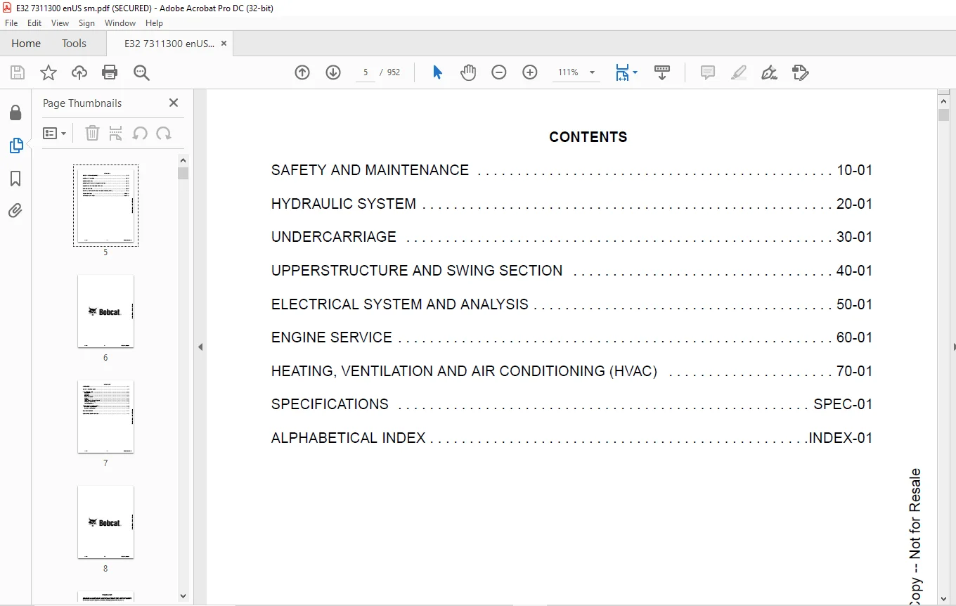
TABLE OF CONTENTS:
Bobcat E32 Compact Excavator Service Manual SN B3Y111001 & Above – PDF DOWNLOAD
MAINTENANCE SAFETY 3
CONTENTS 5
FOREWORD 7
FOREWORD 9
SAFETY INSTRUCTIONS 11
FIRE PREVENTION 13
Maintenance 13
Operation 13
Electrical 13
Hydraulic System 13
Fueling 13
Starting 13
Spark Arrester Exhaust System 13
Welding And Grinding 14
Fire Extinguishers 14
SERIAL NUMBER LOCATIONS 15
Excavator Serial Number 15
Engine Serial Number 15
DELIVERY REPORT 16
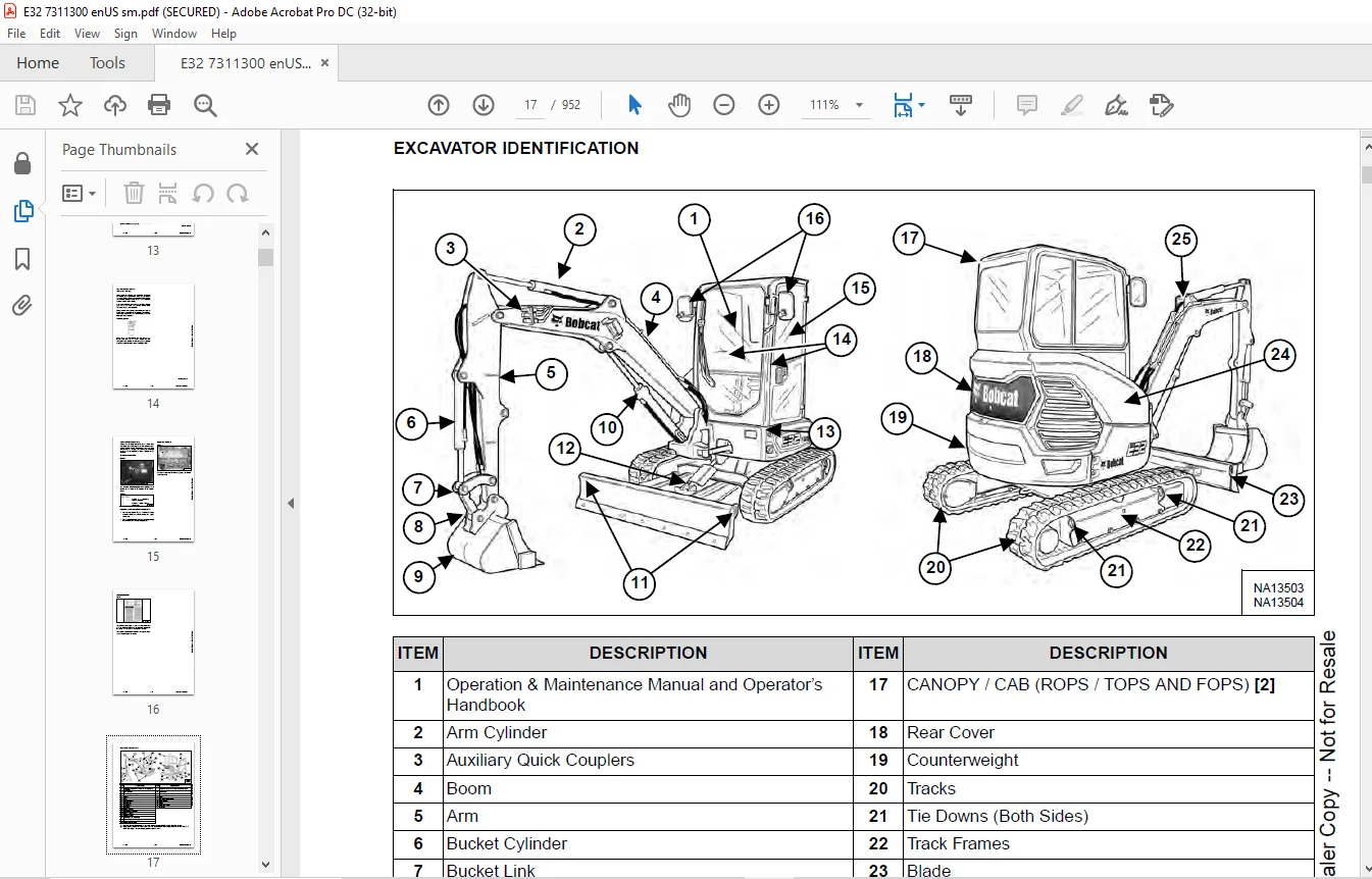
EXCAVATOR IDENTIFICATION 17
SAFETY AND MAINTENANCE 19
LIFTING AND BLOCKING THE EXCAVATOR 23
Procedure 23
LIFTING THE EXCAVATOR 25
Procedure 25
OPERATOR CAB (ROPS / TOPS / FOPS) 27
Description 27
Cab Door 28
Front Window 29
Front Wiper 30
Window Washer Reservoir 30
Right Side Window 31
OPERATOR CANOPY (ROPS / TOPS) 33
Description 33
TRANSPORTING THE EXCAVATOR ON A TRAILER 35
Loading And Unloading 35
Fastening 36
TAILGATE 39
Opening And Closing 39
Adjusting The Latch 39
RIGHT SIDE COVER 41
Opening And Closing 41
SERVICE SCHEDULE 43
Maintenance Intervals 43
AIR CLEANER SERVICE 45
Daily Check 45
Replacing The Filters 45
CAB FILTERS 47
Cleaning And Maintenance 47
ENGINE COOLING SYSTEM 49
Cleaning 49
Checking Level 51
Removing And Replacing Coolant 52
FUEL SYSTEM 53
Fuel Specifications 53
Biodiesel Blend Fuel 53
Filling The Fuel Tank 54
Fuel Filters 55
Draining The Fuel Tank 55
Removing Air From The Fuel System 56
ENGINE LUBRICATION SYSTEM 57
Checking And Adding Engine Oil 57
Engine Oil Chart 57
Removing And Replacing Oil And Filter 58
HYDRAULIC SYSTEM 59
Checking And Adding Hydraulic Fluid 59
Hydraulic / Hydrostatic Fluid Chart 60
Removing And Replacing Hydraulic Filters 61
Removing And Replacing The Hydraulic Fluid 62
LUBRICATION OF THE HYDRAULIC EXCAVATOR 65
Lubrication Locations 65
PIVOT PINS 69
Inspection And Maintenance 69
TRAVEL MOTOR 71
Checking And Adding Oil 71
Removing And Replacing Oil 71
SPARK ARRESTER MUFFLER 73
Cleaning Procedure 73
EMERGENCY EXIT 75
Right Side Rear Window 75
Front Window 75
SEAT BELT 77
Inspection And Maintenance 77
CONTROL CONSOLE LOCKOUTS 79
Inspection And Maintenance 79
TOWING THE EXCAVATOR 81
Procedure 81
REMOTE START TOOL KIT – MEL1563 83
Remote Start Tool Kit – MEL1563 83
Service Tool Harness Control – MEL1565 84
Service Tool Harness Communicator – MEL1566 85
REMOTE START TOOL (SERVICE TOOL) KIT – 7217666 87
Description 87
Remote Start Tool (Service Tool) – 7022042 88
Excavator Service Tool Harness – 6689747 89
Computer Service Tool Harness – 6689746 90
HYDRAULIC SYSTEM 91
HYDRAULIC / HYDROSTATIC SCHEMATICS 97
HYDRAULIC SYSTEM INFORMATION 99
Glossary Of Hydraulic / Hydrostatic Symbols 99
Troubleshooting The Hydraulic Circuit 102
Troubleshooting The Cylinder Circuit 103
Troubleshooting The Swing (Upperstructure Slew) Circuit 104
Troubleshooting The Travel Circuit 105
CYLINDER (BOOM) 107
Testing 107
Removal And Installation 109
Parts Identification 112
Disassembly 113
Assembly 116
CYLINDER (ARM) 121
Testing 121
Removal And Installation 123
Parts Identification 125
Disassembly 126
Assembly 128
CYLINDER (BOOM SWING) 133
Testing 133
Removal And Installation 135
Parts Identification 137
Disassembly 138
Assembly 140
CYLINDER (BUCKET) 145
Testing 145
Removal And Installation 147
Parts Identification 149
Disassembly 150
Assembly 152
CYLINDER (BLADE) 155
Testing 155
Removal And Installation 157
Parts Identification 158
Disassembly 159
Assembly 161
CYLINDER (CLAMP) 165
Testing 165
Removal And Installation 166
Parts Identification 168
Disassembly 169
Assembly 172
CYLINDER (EXTENDABLE ARM) 177
Testing 177
Parts Identification 179
Disassembly 180
Assembly 183
VALVE (MAIN RELIEF) 187
Description 187
VALVE (PORT RELIEF) 189
Testing And Adjusting Port Relief Valve Pressure 189
VALVE (CROSS PORT RELIEF) 191
Testing 191
Removal And Installation 193
Disassembly And Assembly 193
VALVE (PILOT PRESSURE RELIEF) 195
Testing And Adjusting The Pilot Pressure Relief Valve 195
HYDRAULIC CONTROL VALVE 197
Description 197
Removal And Installation 197
Parts Identification 202
Disassembly 203
Assembly 209
Inlet Valve Section Disassembly And Assembly 213
Boom Swing Valve Section Disassembly And Assembly 215
Slew Valve Section Disassembly And Assembly 218
Blade Valve Section Disassembly And Assembly 219
Right And Left Travel Valve Section Disassembly And Assembly 222
Boom Valve Section Disassembly And Assembly 224
Auxiliary, Arm, Bucket And Angle Blade Valve Section Disassembly And Assembly 228
Outlet Valve Section Disassembly And Assembly 230
HYDRAULIC PUMP 233
Hydraulic Pump Work Sheet 233
Pump Testing 235
Description 243
Removal And Installation 243
Coupler Removal And Installation 244
Hydraulic Pump Startup 245
Gear Pump Disassembly And Assembly 246
Piston Pump Parts Identification 248
Piston Pump Disassembly And Assembly 249
MANIFOLD ASSEMBLY / ACCUMULATOR 261
Description 261
Removal And Installation 261
Parts Identification 263
Disassembly And Assembly 264
TRAVEL MOTOR 271
Description 271
Removal And Installation 271
Parts Identification Hydraulic Motor 272
Parts Identification Gear Reduction Hub 273
Disassembly 274
Assembly 288
SWIVEL JOINT (LATER MODELS) 305
Removal And Installation 305
Parts Identification 307
Disassembly And Assembly 308
SWIVEL JOINT (EARLIER MODELS) 311
Removal And Installation 311
Parts Identification Angle Blade Swivel 313
Parts Identification Straight Blade Swivel 314
Disassembly And Assembly 315
SWING MOTOR 317
Removal And Installation 317
Parts Identification 318
Disassembly And Assembly 319
SWING MOTOR (DRIVE CARRIER) 325
Removal And Installation 325
Parts Identification 326
Disassembly And Assembly 327
CONTROL PATTERN SELECTOR VALVE 333
Removal And Installation 333
Parts Identification 334
Disassembly And Assembly 335
RIGHT CONTROL LEVER (JOYSTICK) 337
Testing 337
Handle Removal And Installation 338
Joystick Assembly Removal And Installation 340
Parts Identification 341
Disassembly 342
Assembly 347
LEFT CONTROL LEVER (JOYSTICK) 353
Testing 353
Handle Removal And Installation 354
Joystick Assembly Removal And Installation 356
Parts Identification 357
Disassembly 358
Assembly 363
HYDRAULIC FILTER MOUNT 369
Removal And Installation 369
HYDRAULIC RESERVOIR 371
Removal And Installation 371
OIL COOLER 373
Removal And Installation 373
DIRECT TO TANK VALVE 375
Removal And Installation 375
BLADE CONTROL LEVER 377
Handle Removal And Installation 377
Removal And Installation 379
Parts Identification 380
Disassembly And Assembly 381
CASE DRAIN FILTER MOUNT 385
Removal And Installation 385
TRAVEL CONTROL VALVE 387
Removal And Installation 387
Parts Identification 388
Disassembly And Assembly 389
REMOVING AIR FROM THE HYDRAULIC SYSTEM 395
Procedure 395
HYDRAULIC X-CHANGE MANIFOLD 397
Removal And Installation 397
Parts Identification 398
Disassembly And Assembly 399
SECONDARY AUXILIARY VALVE 405
Removal And Installation 405
Parts Identification 407
Disassembly And Assembly 408
VALVE (BOOM LOCK) 411
Removal And Installation 411
VALVE (ARM LOCK) 413
Removal And Installation 413
UNDERCARRIAGE 415
BLADE 417
Removal And Installation 417
TRACK UNDERCARRIAGE COMPONENTS (RUBBER TRACK) 419
Description 419
Track Lug Height 419
Checking Tension 420
Adjusting Tension 422
Removal And Installation 423
Idler Removal And Installation 425
Parts Identification 426
Idler Disassembly 427
Idler Assembly 429
Track Tensioner Removal And Installation 432
Track Tensioner Parts Identification 433
Track Tensioner Disassembly And Assembly 434
Roller Removal And Installation 436
Sprocket Removal And Installation 437
TRACK UNDERCARRIAGE COMPONENTS (STEEL TRACK) 439
Description 439
Checking Tension 440
Adjusting Tension 442
Track Removal And Installation 444
Idler Removal And Installation 447
Idler Parts Identification 448
Idler Disassembly 449
Idler Assembly 451
Track Tensioner Removal And Installation 454
Track Tensioner Parts Identification 455
Track Tensioner Disassembly And Assembly 456
Roller Removal And Installation 458
Sprocket Removal And Installation 459
Guide Plate Removal And Installation 459
TRACK MAINTENANCE 461
Track Damage Identification 461
SWING CIRCLE GEAR 473
Swing Bearing Removal 473
Swing Bearing Installation 474
UPPERSTRUCTURE AND SWING SECTION 475
UPPERSTRUCTURE 479
Removal 479
Installation 481
ROPS CANOPY 483
Removal And Installation 483
CAB 487
Removal And Installation 487
Door Removal And Installation 490
Front Window Removal And Installation 491
Front Window Disassembly And Assembly 492
Front Window Adjustment 494
Glass Removal 496
Glass Installation 497
SEAT 503
Removal And Installation 503
RIGHT CONSOLE 505
Console Cover Removal And Installation 505
LEFT CONSOLE 511
Lower Console Cover Removal And Installation 511
Upper Console Cover Removal And Installation 512
Compression Spring Removal And Installation 514
Lock Lever Removal And Installation 516
Console Removal And Installation 517
LEFT UPPERSTRUCTURE COVER 519
Removal And Installation 519
RIGHT UPPERSTRUCTURE COVER 521
Removal And Installation 521
COUNTERWEIGHT 523
Removal And Installation 523
Add On Counterweight Removal And Installation 527
TRAVEL LEVERS AND PEDALS 529
Removal And Installation 529
Disassembly And Assembly 529
FLOOR MAT 531
Removal And Installation 531
FUEL TANK 533
Removal And Installation (Canopy Equipped Excavator) 533
Removal And Installation (Cab Equipped Excavator) 534
Fuel Tank Fitting Removal And Installation 536
HORN 537
Removal And Installation 537
SWING FRAME 539
Removal And Installation 539
Boom Swing Frame Hose Routing 542
Bushing Removal 543
Bushing Installation 544
BOOM 545
Removal And Installation 545
ARM (STANDARD AND LONG) 547
Removal And Installation 547
Arm To Boom Bushing Removal And Installation 548
Arm To Bucket And Bucket Link Bushing Removal And Installation 549
ARM (EXTENDABLE) 551
Removal And Installation 551
Arm To Boom Bushing Removal And Installation 552
Arm To Bucket Bushing Removal And Installation 553
Disassembly And Assembly 554
Shimming Procedure 562
BUCKET 563
Bucket Teeth Removal And Installation 563
Bucket Side Cutting Edge Removal And Installation 564
CLAMP 565
Removal And Installation 565
TAILGATE 567
Removal And Installation 567
Disassembly And Assembly 568
X-CHANGE 571
Removal And Installation 571
Disassembly 572
Assembly 573
X-CHANGE (HYDRAULIC) (EARLIER MODELS) 575
Removal And Installation 575
Parts Identification 577
Disassembly 578
Assembly 583
X-CHANGE (HYDRAULIC) (LATER MODELS) 591
Removal And Installation 591
Parts Identification 593
Disassembly 594
Assembly 600
Expansion Plug Installation 608
QUICK COUPLER (KLAC™ SYSTEM) 609
Troubleshooting 609
Daily Inspection 609
Removal And Installation 610
Parts Identification 612
Disassembly 613
Assembly 615
QUICK COUPLER (LEHNHOFF® SYSTEM) 617
Troubleshooting 617
Daily Inspection 617
Removal (MS03 And MS08) 618
Installation (MS03 And MS08) 619
Parts Identification (MS03) 620
Disassembly And Assembly (MS03) 621
Parts Identification (MS08) 622
Disassembly (MS08) 623
Assembly (MS08) 626
QUICK COUPLER (PIN GRABBER) 631
Troubleshooting 631
Daily Inspection 632
Removal And Installation 633
Parts Identification 634
Disassembly And Assembly 635
RIGHT SIDE COVER 639
Removal And Installation 639
Latch Removal And Installation 640
LEFT SIDE COVER 641
Removal And Installation 641
TOOL BOX 643
Removal And Installation 643
ELECTRICAL SYSTEM AND ANALYSIS 645
ELECTRICAL SCHEMATICS 647
ELECTRICAL SYSTEM INFORMATION 681
Troubleshooting Chart 681
Description 682
Fuse And Relay Location / Identification 682
BATTERY 685
Servicing 685
Maintaining Battery Charge Level 685
Battery Service During Machine Storage 685
Battery Testing 686
Battery Charging 686
Removal And Installation 687
Using A Booster Battery (Jump Starting) 688
ALTERNATOR 689
Belt Adjustment 689
Belt Replacement 689
Charging System Inspection 690
Alternator Voltage Testing 691
Low Voltage Testing 691
High Voltage Testing 692
Removal And Installation 693
Parts Identification 695
STARTER 697
Testing 697
Removal And Installation 698
Parts Identification 699
LIGHTS 701
Removal And Installation 701
Boom Light Removal And Installation 702
Boom Light Bulb Replacement 702
MAGNETIC LOCKOUT SENSOR 703
Removal And Installation 703
FUEL LEVEL SENDER 705
Removal And Installation 705
Testing 706
DIAGNOSTIC SERVICE CODES 707
Viewing Service Codes 707
Service Codes List 708
CONTROL PANEL SETUP 711
Panel Setup (Deluxe Instrument Panel) 711
Password Setup (Keyless Start Panel) 717
Password Setup (Deluxe Instrument Panel) 718
Maintenance Clock 720
INSTRUMENT PANEL 725
Removal And Installation 725
CONTROLLER 727
Description 727
Auxiliary Controller Removal And Installation 727
Gateway Controller Removal And Installation 729
KEY SWITCH 731
Removal And Installation 731
WIPER MOTOR 733
Removal And Installation 733
MOTION ALARM SYSTEM 735
Description 735
Inspecting 735
Adjusting Switch Position 736
SERVICE PC (LAPTOP COMPUTER) 737
Connecting The Remote Start Tool 737
Connecting Remote Start Tool (Service Tool) 737
SHUT-OFF SWITCH 739
Description 739
Removal And Installation 739
TRAVEL MOTOR AUTO-SHIFT 741
Auto-Shift Drive System (If Equipped) 741
Troubleshooting 742
BOBCAT MACHINE IQ WIRELESS COMMUNICATIONS 743
Description 743
Controller Removal And Installation 743
Antenna Removal And Installation 746
Procedure 747
ENGINE SERVICE 749
ENGINE INFORMATION 751
Description 751
Specifications 752
Crankshaft Re-Grind Data 758
Torque For Kubota® Metric Bolts 759
Troubleshooting 760
Engine Removal And Installation 761
Compression – Testing 768
ENGINE SPEED CONTROL 769
Removal And Installation 769
Calibration 770
Actuator Removal And Installation 773
MUFFLER 775
Removal And Installation 775
AIR CLEANER 777
Removal And Installation 777
ENGINE COOLING SYSTEM 779
Radiator Removal And Installation 779
Fan Removal And Installation 782
Water Pump Removal And Installation 783
Water Pump Disassembly And Assembly 784
Thermostat Housing Removal And Installation 785
Thermostat – Testing 786
LUBRICATION SYSTEM 787
Oil Pan Removal And Installation 787
Oil Pump Removal And Installation 788
Oil Pump Inspection 788
Engine Oil Pressure – Testing 789
FUEL SYSTEM 791
Fuel Shutoff Solenoid – Testing 791
Fuel Shut-off Solenoid Removal And Installation 792
Fuel Injection Pump – Testing 793
Fuel Injection Pump Removal And Installation 794
Fuel Injection Pump – Timing 797
Fuel Camshaft Removal And Installation 799
Fuel Camshaft Governor 800
Fuel Injector Removal And Installation 801
Fuel Injector Nozzle Pressure – Testing 803
Nozzle Spray Condition 804
Valve Seat Tightness 804
CYLINDER HEAD 805
Glow Plugs – Testing 805
Glow Plugs Removal And Installation 806
Valve Clearance Adjustment 807
Valve Timing – Inspecting 807
Cylinder Head Removal And Installation 808
Cylinder Head Disassembly And Assembly 811
Cylinder Head – Servicing 812
Cylinder Head Top Clearance 812
Valve Guide – Inspecting 813
Valve Guide Removal And Installation 814
Reconditioning The Valve And Valve Seat 815
Valve Spring 816
Valve Tappets 817
Rocker Arm And Shaft – Inspecting 818
Push Rod Alignment – Inspecting 818
CRANKSHAFT AND PISTONS 819
Piston And Connecting Rod Removal And Installation 819
Piston And Connecting Rod – Servicing 821
Cylinder Bore – Inspecting 823
Connecting Rod Alignment 824
Crankshaft Gear Removal And Installation 825
Crankshaft And Bearings Removal And Installation 826
Crankshaft And Bearings – Servicing 829
CAMSHAFT AND TIMING GEARS 833
Timing Gearcase Cover Removal And Installation 833
Timing Gears Backlash – Inspecting 836
Idle Gear And Camshaft Removal And Installation 837
Camshaft – Servicing 839
Idle Gear And Shaft – Servicing 840
FLYWHEEL AND HOUSING 841
Hydraulic Pump Coupler Removal And Installation 841
Flywheel Removal And Installation 843
Flywheel Ring Gear 843
HEATING, VENTILATION AND AIR CONDITIONING (HVAC) 845
AIR CONDITIONING SYSTEM FLOW 847
Description 847
Chart 848
Components 849
Safety Equipment 852
REGULAR MAINTENANCE 853
Cab Filters 853
Air Conditioning Compressor Belt Adjustment 855
Air Conditioning Compressor Belt Replacement 855
Condenser 857
Air Conditioning Lubrication 857
Evaporator / Heater Coil 858
Air Conditioning Service Chart 859
TROUBLESHOOTING 861
Blower Motor Does Not Operate 861
Blower Motor Operates Normally, But Air Flow Is Insufficient 861
Insufficient Cooling Although Air Flow And Compressor Operation Are Normal 861
The Compressor Operates Improperly Or Not At All 861
Gauge Pressure Related Troubleshooting 862
Temperature / Pressure Chart 863
Poor A/C Performance 864
HVAC Repair And Leaks 864
Electrical System 865
Engine Coolant Bypassing The Heater Valve 867
SYSTEM CHARGING AND RECLAMATION 869
Refrigerant Identification 869
Reclamation And Charging With Recovery / Charging Unit 871
COMPRESSOR 873
Removal And Installation 873
Oil 874
Oil Check 875
CONDENSER 877
Removal And Installation 877
RECEIVER / DRIER 879
Receiver / Drier Removal And Installation 879
Pressure Switch Removal And Installation 880
EVAPORATOR / HEATER UNIT 881
Removal And Installation 881
THERMOSTAT 885
Description 885
Removal And Installation 886
EXPANSION VALVE 889
Removal And Installation 889
EVAPORATOR COIL 891
Removal And Installation 891
HEATER COIL 893
Removal And Installation 893
BLOWER FAN 895
Removal And Installation 895
HEATER VALVE 897
Removal And Installation 897
HVAC DUCT 899
Removal And Installation 899
AUTO HVAC 901
Description 901
ATM Removal And Installation 901
ATM Diagnostic Codes 902
Blower Fan Drive Assembly Removal And Installation 903
De-Icing Sensor Removal And Installation 904
Inside And After Coil Sensor Testing 904
SPECIFICATIONS 907
EXCAVATOR SPECIFICATIONS 909
Excavator Machine Dimensions 909
Excavator Machine Dimensions – Standard Arm 910
Excavator Machine Dimensions – Long Arm 911
Excavator Machine Dimensions – Extendable Arm 912
Rated Lift Capacity – Standard Arm 913
Rated Lift Capacity – Standard Arm With Additional Counterweight 914
Rated Lift Capacity – Long Arm 915
Rated Lift Capacity – Extendable Arm 916
Performance 917
Controls 917
Engine 918
Hydraulic System 918
Hydraulic Cycle Times 919
Hydraulic Cylinders 919
Drive System 919
Slew System 919
Undercarriage 919
Electrical 920
Capacities 920
Tracks 921
Ground Pressure 921
TECHNICAL SERVICE GUIDE SPECIFICATIONS 923
Engine 923
Engine Torques 923
Cooling System 923
Excavator Torques 923
TORQUE SPECIFICATION FOR BOLTS 925
Torque For General SAE Bolts 925
Torque For General Metric Bolts 926
HYDRAULIC CONNECTION SPECIFICATIONS 927
O-ring Face Seal Connection 927
Straight Thread O-ring Fitting 927
Tubelines And Hoses 928
Flare Fitting 928
O-ring Flare Fitting 929
Port Seal Fitting 931
Push To Connect Fittings 932
HYDRAULIC FLUID SPECIFICATIONS 935
Specifications 935
CONVERSIONS 937
Decimal And Millimeter Equivalent Chart 937
U S To Metric Conversion Chart 938
SERVICE TOOLS REQUIRED 939
Remote Start Tools 939
Hydraulic Tools 940
Engine Tools 943
Electrical Tools 945
General Tools 945
HVAC Tools 946
ALPHABETICAL INDEX 947
SERVICE SCHEDULE SYMBOLS 951
Questions? Email us: [email protected]
https://vimeo.com/841812726?share=copy
PLEASE NOTE:
- This is the same manual used by the dealers to diagnose and troubleshoot your vehicle
- You will be directed to the download page as soon as the purchase is completed. The whole payment and downloading process will take anywhere between 2-5 minutes
- Need any other service / repair / parts manual, please feel free to contact [email protected] . We still have 50,000 manuals unlisted
s.m


