Bobcat E34 Compact Excavator Service Manual SN B3Y311001 & Above – PDF DOWNLOAD
$33.95
Bobcat E34 Compact Excavator Service Manual SN B3Y311001 & Above – PDF DOWNLOAD
S/N B3Y311001 & Above
Description
Bobcat E34 Compact Excavator Service Manual SN B3Y311001 & Above – PDF DOWNLOAD
FILE DETAILS:
Bobcat E34 Compact Excavator Service Manual SN B3Y311001 & Above – PDF DOWNLOAD
Language : English
Pages :837
Downloadable : Yes
File Type : PDF
DESCRIPTION:
Bobcat E34 Compact Excavator Service Manual SN B3Y311001 & Above – PDF DOWNLOAD
FOREWORD
This manual is for the Bobcat excavator mechanic. It provides necessary servicing and adjustment procedures for the Bobcat excavator and its component parts and systems. Refer to the Operation & Maintenance Manual for operating instructions, starting procedure, daily checks, etc.
SAFETY INSTRUCTIONS
Instructions are necessary before operating or servicing machine. Read and understand the Operation & Maintenance Manual, Operator’s Handbook and signs (decals) on machine. Follow warnings and instructions in the manuals when making repairs, adjustments or servicing. Check for correct function after adjustments, repairs or service. Untrained operators and failure to follow instructions can cause injury or death.
The following publications provide information on the safe use and maintenance of the Bobcat machine and attachments:
- The Delivery Report is used to assure that complete instructions have been given to the new owner and that the machine is in safe operating condition.
- The Operation & Maintenance Manual delivered with the machine or attachment contains operating information as well as routine maintenance and service procedures. It is a part of the machine and can be stored in a container provided on the machine. Replacement Operation & Maintenance Manuals can be ordered from your Bobcat dealer.
- Machine signs (decals) instruct on the safe operation and care of your Bobcat machine or attachment. The signs and their locations are shown in the Operation & Maintenance Manual. Replacement signs are available from your Bobcat dealer.
- An Operator’s Handbook fastened to the operator cab. It’s brief instructions are convenient to the operator. The handbook is available from your dealer in an English edition or one of many other languages. See your Bobcat dealer for more information on translated versions.
- The AEM Safety Manual delivered with the machine gives general safety information.
- The Service Manual and Parts Manual are available from your dealer for use by mechanics to do shoptype service and repair work.
IMAGES PREVIEW OF THE MANUAL:
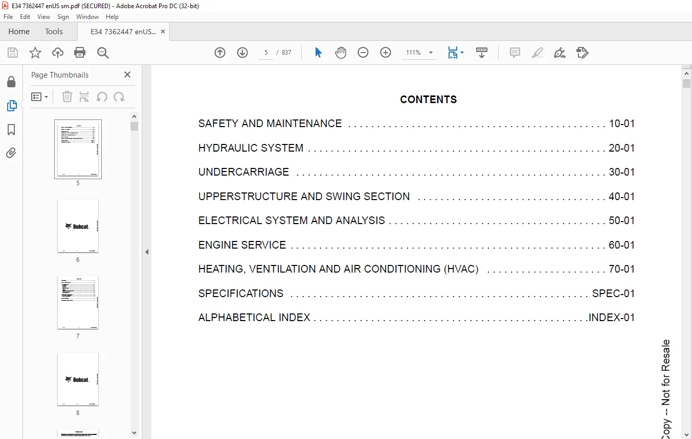
TABLE OF CONTENTS:
Bobcat E34 Compact Excavator Service Manual SN B3Y311001 & Above – PDF DOWNLOAD
MAINTENANCE SAFETY 3
CONTENTS 5
FOREWORD 7
FOREWORD 9
SAFETY INSTRUCTIONS 11
FIRE PREVENTION 13
Maintenance 13
Operation 13
Electrical 13
Hydraulic System 13
Fueling 13
Starting 13
Spark Arrester Exhaust System 13
Welding And Grinding 14
Fire Extinguishers 14
SERIAL NUMBER LOCATIONS 15
Excavator Serial Number 15
Engine Serial Number 15
DELIVERY REPORT 16
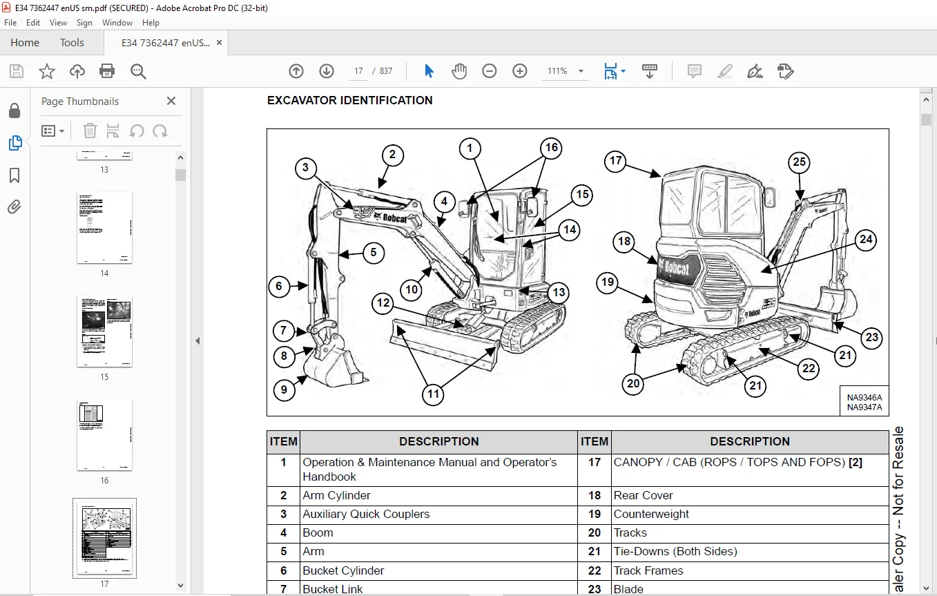
EXCAVATOR IDENTIFICATION 17
SAFETY AND MAINTENANCE 19
LIFTING AND BLOCKING THE EXCAVATOR 23
Procedure 23
LIFTING THE EXCAVATOR 25
Procedure 25
OPERATOR CAB (ROPS / TOPS / FOPS) 27
Description 27
Cab Door 27
Front Window 28
Front Wiper 30
Window Washer Reservoir 30
Right Side Window 31
OPERATOR CANOPY (ROPS / TOPS / FOPS) 33
Description 33
TRANSPORTING THE EXCAVATOR ON A TRAILER 35
Loading And Unloading 35
Fastening 36
TAILGATE 39
Opening And Closing 39
Adjusting The Latch 39
RIGHT SIDE COVER 41
Opening And Closing 41
SERVICE SCHEDULE 43
Maintenance Intervals 43
Inspection Checkbook 44
AIR CLEANER SERVICE 45
Daily Check 45
Replacing The Filter Elements 45
CAB FILTERS 47
Cleaning And Maintenance 47
ENGINE COOLING SYSTEM 49
Cleaning 49
Checking Level 50
Removing And Replacing Coolant 51
FUEL SYSTEM 53
Fuel Specifications 53
Biodiesel Blend Fuel 53
Filling The Fuel Tank 54
Fuel Filters 55
Draining The Fuel Tank 56
Removing Air From The Fuel System 57
ENGINE LUBRICATION SYSTEM 59
Checking And Adding Engine Oil 59
Engine Oil Chart 59
Removing And Replacing Oil And Filter 60
HYDRAULIC SYSTEM 61
Checking And Adding Hydraulic Fluid 61
Hydraulic / Hydrostatic Fluid Chart 62
Removing And Replacing Hydraulic Filters 62
Removing And Replacing Hydraulic Fluid 63
LUBRICATING THE EXCAVATOR 65
Lubrication Locations 65
PIVOT PINS 69
Inspection And Maintenance 69
TRAVEL MOTOR 71
Checking And Adding Oil 71
Removing And Replacing Oil 71
SPARK ARRESTER MUFFLER 73
Cleaning Procedure 73
EMERGENCY EXIT 75
Right Side Rear Window 75
Front Window 75
SEAT BELT 77
Inspection And Maintenance 77
CONTROL CONSOLE LOCKOUTS 79
Inspection And Maintenance 79
TOWING THE EXCAVATOR 81
Procedure 81
REMOTE START TOOL KIT – MEL1563 83
Remote Start Tool Kit – MEL1563 83
Service Tool Harness Control – MEL1565 84
Service Tool Harness Communicator – MEL1566 85
REMOTE START TOOL (SERVICE TOOL) KIT – 7217666 87
Description 87
Remote Start Tool (Service Tool) – 7022042 88
Excavator Service Tool Harness – 6689747 89
Computer Service Tool Harness – 6689746 90
HYDRAULIC SYSTEM 91
HYDRAULIC / HYDROSTATIC SCHEMATICS 95
HYDRAULIC SYSTEM INFORMATION 97
Glossary Of Hydraulic / Hydrostatic Symbols 97
Troubleshooting The Hydraulic Circuit 100
Troubleshooting The Cylinder Circuit 101
Troubleshooting The Swing (Upperstructure Slew) Circuit 102
Troubleshooting The Travel Circuit 103
CYLINDER (BOOM) 105
Testing 105
Removal And Installation 107
Parts Identification 110
Disassembly 111
Assembly 114
CYLINDER (ARM) 119
Testing 119
Removal And Installation 121
Parts Identification 123
Disassembly 124
Assembly 126
CYLINDER (BOOM SWING) 131
Testing 131
Removal And Installation 133
Parts Identification (Earlier Models) 135
Disassembly (Earlier Models) 136
Assembly (Earlier Models) 138
Parts Identification (Later Models) 142
Disassembly (Later Models) 143
Assembly (Later Models) 145
CYLINDER (BUCKET) 149
Testing 149
Removal And Installation 150
Parts Identification 152
Disassembly 153
Assembly 155
CYLINDER (BLADE) 159
Testing 159
Removal And Installation 161
Parts Identification (Earlier Models) 162
Disassembly (Earlier Models) 163
Assembly (Earlier Models) 165
Parts Identification (Later Models) 168
Disassembly (Later Models) 169
Assembly (Later Models) 171
CYLINDER (CLAMP) 175
Testing 175
Removal And Installation 176
Parts Identification 178
Disassembly 179
Assembly 182
VALVE (MAIN RELIEF) 187
Description 187
VALVE (PORT RELIEF) 189
Testing And Adjusting Port Relief Valve Pressure 189
VALVE (CROSS PORT RELIEF) 191
Testing 191
Removal And Installation 193
Disassembly And Assembly 193
VALVE (PILOT PRESSURE RELIEF) 195
Testing And Adjusting The Pilot Pressure Relief Valve 195
HYDRAULIC CONTROL VALVE 197
Description 197
Removal And Installation 198
Parts Identification 202
Disassembly 203
Assembly 209
Inlet Valve Section Disassembly And Assembly 212
Boom Swing Valve Section Disassembly And Assembly 214
Slew Valve Section Disassembly And Assembly 216
Blade Valve Section Disassembly And Assembly 217
Right And Left Travel Valve Section Disassembly And Assembly 220
Boom Valve Section Disassembly And Assembly 221
Auxiliary, Arm, Bucket And Angle Blade Valve Section Disassembly And Assembly 225
Outlet Valve Section Disassembly And Assembly 227
HYDRAULIC PUMP 229
Hydraulic Pump Work Sheet 229
Pump Testing 231
Description 239
Removal And Installation 239
Coupler Removal And Installation 240
Hydraulic Pump Startup 241
Gear Pump Disassembly And Assembly 242
Piston Pump Parts Identification 244
Piston Pump Disassembly And Assembly 245
MANIFOLD ASSEMBLY / ACCUMULATOR 257
Description 257
Removal And Installation 257
Parts Identification 259
Disassembly And Assembly 260
TRAVEL MOTOR 267
Description 267
Removal And Installation 267
Parts Identification Hydraulic Motor 268
Parts Identification Gear Reduction Hub 269
Disassembly 270
Assembly 284
SWIVEL JOINT 299
Removal And Installation 299
Parts Identification 301
Disassembly And Assembly 302
SWING MOTOR 305
Removal And Installation 305
Parts Identification 306
Disassembly And Assembly 307
SWING MOTOR (DRIVE CARRIER) 313
Removal And Installation 313
Parts Identification 314
Disassembly And Assembly 315
CONTROL PATTERN SELECTOR VALVE 321
Removal And Installation 321
Parts Identification 322
Disassembly And Assembly 323
RIGHT CONTROL LEVER (JOYSTICK) 325
Testing 325
Handle Removal And Installation 326
Joystick Assembly Removal And Installation 329
Parts Identification 330
Disassembly And Assembly 331
LEFT CONTROL LEVER (JOYSTICK) 333
Testing 333
Handle Removal And Installation 334
Joystick Assembly Removal And Installation 337
Parts Identification 338
Disassembly And Assembly 339
HYDRAULIC FILTER MOUNT 341
Removal And Installation 341
HYDRAULIC RESERVOIR 343
Removal And Installation 343
OIL COOLER 345
Removal And Installation 345
DIRECT TO TANK VALVE 347
Removal And Installation 347
BLADE CONTROL LEVER 349
Handle Removal And Installation 349
Removal And Installation 351
Parts Identification 352
Disassembly And Assembly 353
CASE DRAIN FILTER MOUNT 357
Removal And Installation 357
TRAVEL CONTROL VALVE 359
Removal And Installation 359
Parts Identification 360
Disassembly And Assembly 361
REMOVING AIR FROM THE HYDRAULIC SYSTEM 367
Procedure 367
HYDRAULIC X-CHANGE MANIFOLD 369
Removal And Installation 369
Parts Identification 370
Disassembly And Assembly 371
SECONDARY AUXILIARY VALVE 373
Removal And Installation 373
Parts Identification 375
Disassembly And Assembly 376
VALVE (BOOM LOCK) 379
Removal And Installation 379
VALVE (ARM LOCK) 381
Removal And Installation 381
UNDERCARRIAGE 383
BLADE 385
Removal And Installation 385
TRACK UNDERCARRIAGE COMPONENTS (RUBBER TRACK) 387
Description 387
Track Lug Height 387
Checking Tension 388
Adjusting Tension 390
Removal And Installation 391
Idler Removal And Installation 393
Idler Parts Identification 394
Idler Disassembly 395
Idler Assembly 397
Track Tensioner Removal And Installation 400
Track Tensioner Parts Identification 401
Track Tensioner Disassembly And Assembly 402
Roller Removal And Installation 404
Sprocket Removal And Installation 404
TRACK UNDERCARRIAGE COMPONENTS (STEEL TRACK) 405
Description 405
Checking Tension 406
Adjusting Tension 408
Track Removal And Installation 409
Idler Removal And Installation 412
Idler Parts Identification 413
Idler Disassembly 414
Idler Assembly 416
Track Tensioner Removal And Installation 419
Track Tensioner Parts Identification 420
Track Tensioner Disassembly And Assembly 421
Roller Removal And Installation 423
Sprocket Removal And Installation 424
Guide Plate Removal And Installation 424
TRACK MAINTENANCE 425
Track Damage Identification 425
SWING CIRCLE GEAR 437
Swing Bearing Removal 437
Swing Bearing Installation 438
UPPERSTRUCTURE AND SWING SECTION 439
UPPERSTRUCTURE 443
Removal 443
Installation 445
ROPS CANOPY 447
Removal And Installation 447
CAB 451
Removal And Installation 451
Door Removal And Installation 455
Front Window Removal And Installation 456
Right Side Sliding Window Removal And Installation 458
Glass Removal 461
Glass Installation 462
SEAT 467
Removal And Installation 467
Seat Mount Removal And Installation 468
RIGHT CONSOLE 469
Console Cover Removal And Installation 469
LEFT CONSOLE 473
Lower Console Cover Removal And Installation 473
Upper Console Cover Removal And Installation 474
Compression Spring Removal And Installation 477
Lock Lever Removal And Installation 479
Console Removal And Installation 479
LEFT UPPERSTRUCTURE COVER 481
Removal And Installation 481
RIGHT UPPERSTRUCTURE COVER 483
Removal And Installation 483
COUNTERWEIGHT 485
Removal And Installation 485
Add On Counterweight Removal And Installation 489
TRAVEL LEVERS AND PEDALS 491
Removal And Installation 491
Disassembly And Assembly 491
FLOOR MAT AND FLOORPLATE 493
Removal And Installation 493
FUEL TANK 495
Removal And Installation 495
Fuel Tank Fitting Removal And Installation 496
HORN 497
Removal And Installation 497
SWING FRAME 499
Removal And Installation 499
Boom Swing Frame Hose Routing 502
Bushing Removal 503
Bushing Installation 504
BOOM 505
Removal And Installation 505
ARM (STANDARD AND LONG) 507
Removal And Installation 507
Arm To Boom Bushing Removal And Installation 508
Arm To Bucket And Bucket Link Bushing Removal And Installation 509
BUCKET 511
Bucket Teeth Removal And Installation 511
CLAMP 513
Removal And Installation 513
TAILGATE 515
Removal And Installation 515
Disassembly And Assembly 516
QUICK COUPLER (KLAC™ SYSTEM) 519
Troubleshooting 519
Daily Inspection 519
Removal And Installation 520
Parts Identification 522
Disassembly 523
Assembly 525
QUICK COUPLER (PIN GRABBER) 527
Troubleshooting 527
Daily Inspection 528
Removal And Installation 529
Parts Identification 530
Disassembly And Assembly 531
RIGHT SIDE COVER 535
Removal And Installation 535
Latch Removal And Installation 535
LEFT SIDE COVER 537
Removal And Installation 537
TOOL BOX 539
Removal And Installation 539
ELECTRICAL SYSTEM AND ANALYSIS 541
ELECTRICAL SCHEMATICS 543
ELECTRICAL SYSTEM INFORMATION 566
Troubleshooting Chart 566
Description 567
Fuse And Relay Location / Identification 567
BATTERY 570
Servicing 570
Maintaining Battery Charge Level 570
Battery Service During Machine Storage 570
Battery Testing 571
Battery Charging 571
Removal And Installation 572
Using A Booster Battery (Jump Starting) 573
ALTERNATOR 574
Belt Adjustment 574
Belt Replacement 574
Charging System Inspection 575
Alternator Voltage Testing 576
Low Voltage Testing 576
High Voltage Testing 577
Removal And Installation 578
Parts Identification 580
STARTER 582
Testing 582
Removal And Installation 583
Parts Identification 584
LIGHTS 586
Boom Light Removal And Installation 586
Boom Light Bulb Replacement 587
MAGNETIC LOCKOUT SENSOR 588
Removal And Installation 588
FUEL LEVEL SENDER 590
Removal And Installation 590
Testing 591
DIAGNOSTIC SERVICE CODES 592
Viewing Service Codes 592
Number Codes List 593
CONTROL PANEL SETUP 596
Panel Setup (Deluxe Instrument Panel) 596
Password Setup (Keyless Start Panel) 602
Password Setup (Deluxe Instrument Panel) 604
Maintenance Clock 606
INSTRUMENT PANEL 612
Removal And Installation 612
CONTROLLER 614
Description 614
Auxiliary Controller Removal And Installation 614
Gateway Controller Removal And Installation 616
KEY SWITCH 618
Removal And Installation 618
WIPER MOTOR 620
Removal And Installation 620
MOTION ALARM SYSTEM 622
Description 622
Inspecting 622
Adjusting Switch Position 623
SERVICE PC (LAPTOP COMPUTER) 624
Connecting The Remote Start Tool 624
Connecting Remote Start Tool (Service Tool) 624
SHUT-OFF SWITCH 626
Description 626
Removal And Installation 627
TRAVEL MOTOR AUTO-SHIFT 628
Auto-Shift Drive System (If Equipped) 628
Troubleshooting 629
ENGINE SPEED CONTROL 630
Removal And Installation 630
AUTO IDLE PRESSURE SENSOR 632
Description 632
Removal And Installation 633
BOBCAT MACHINE IQ WIRELESS COMMUNICATIONS 634
Description 634
Removal And Installation 634
Procedure 635
ENGINE SERVICE 636
ENGINE INFORMATION 638
Description 638
Specifications 639
Crankshaft Re-grind Data 645
Torque For Kubota® Metric Bolts 646
Troubleshooting 647
Engine Removal And Installation 648
Compression – Testing 655
ENGINE SPEED CONTROL 656
Removal And Installation 656
Calibration 657
Actuator Removal And Installation 660
MUFFLER 662
Removal And Installation 662
AIR CLEANER 664
Removal And Installation 664
ENGINE COOLING SYSTEM 666
Radiator Removal And Installation 666
Fan Removal And Installation 669
Water Pump Removal And Installation 670
Water Pump Disassembly And Assembly 670
Thermostat Housing Removal And Installation 671
Thermostat – Testing 671
LUBRICATION SYSTEM 672
Oil Pan Removal And Installation 672
Oil Pump Removal And Installation 673
Oil Pump Inspection 673
Engine Oil Pressure – Testing 674
FUEL SYSTEM 676
Fuel Shutoff Solenoid – Testing 676
Fuel Shut-off Solenoid Removal And Installation 677
Fuel Injection Pump – Testing 678
Fuel Injection Pump Removal And Installation 679
Fuel Injection Pump – Timing 682
Fuel Camshaft Removal And Installation 684
Fuel Camshaft Governor 685
Fuel Injector Removal And Installation 686
Fuel Injector Nozzle Pressure – Testing 689
Nozzle Spray Condition 690
Valve Seat Tightness 690
CYLINDER HEAD 692
Glow Plugs – Testing 692
Glow Plugs Removal And Installation 693
Valve Clearance Adjustment 694
Valve Timing – Inspecting 694
Cylinder Head Removal And Installation 695
Cylinder Head Disassembly And Assembly 698
Cylinder Head – Servicing 699
Cylinder Head Top Clearance 699
Valve Guide – Inspecting 700
Valve Guide Removal And Installation 701
Reconditioning The Valve And Valve Seat 702
Valve Spring 703
Valve Tappets 704
Rocker Arm And Shaft – Inspecting 705
Push Rod Alignment – Inspecting 705
CRANKSHAFT AND PISTONS 706
Piston And Connecting Rod Removal And Installation 706
Piston And Connecting Rod – Servicing 708
Cylinder Bore – Inspecting 710
Connecting Rod Alignment 710
Crankshaft Gear Removal And Installation 711
Crankshaft And Bearings Removal And Installation 712
Crankshaft And Bearings – Servicing 714
CAMSHAFT AND TIMING GEARS 718
Timing Gearcase Cover Removal And Installation 718
Timing Gears Backlash – Inspecting 721
Idle Gear And Camshaft Removal And Installation 722
Camshaft – Servicing 724
Idle Gear And Shaft – Servicing 725
FLYWHEEL AND HOUSING 726
Hydraulic Pump Coupler Removal And Installation 726
Flywheel Removal And Installation 728
Flywheel Ring Gear 728
HEATING, VENTILATION AND AIR CONDITIONING (HVAC) 730
AIR CONDITIONING SYSTEM FLOW 732
Description 732
Chart 733
Components 734
Safety Equipment 737
REGULAR MAINTENANCE 738
Cab Filters 738
Air Conditioning Compressor Belt Adjustment 740
Air Conditioning Compressor Belt Replacement 740
Condenser 741
Air Conditioning Lubrication 741
Evaporator / Heater Coil 742
Air Conditioning Service Chart 743
TROUBLESHOOTING 744
Blower Motor Does Not Operate 744
Blower Motor Operates Normally, But Air Flow Is Insufficient 744
Insufficient Cooling Although Air Flow And Compressor Operation Are Normal 744
The Compressor Operates Improperly Or Not At All 744
Gauge Pressure Related Troubleshooting 745
Temperature / Pressure Chart 746
Poor A/C Performance 747
HVAC Repair And Leaks 747
Electrical System 748
Engine Coolant Bypassing The Heater Valve 750
SYSTEM CHARGING AND RECLAMATION 752
Refrigerant Identification 752
Reclamation And Charging With Recovery / Charging Unit 754
COMPRESSOR 756
Removal And Installation 756
Oil 757
Oil Check 758
CONDENSER 760
Removal And Installation 760
RECEIVER / DRIER 762
Receiver / Drier Removal And Installation 762
Pressure Switch Removal And Installation 763
EVAPORATOR / HEATER UNIT 764
Removal And Installation 764
THERMOSTAT 768
Description 768
Removal And Installation 769
EXPANSION VALVE 772
Removal And Installation 772
EVAPORATOR COIL 774
Removal And Installation 774
HEATER COIL 776
Removal And Installation 776
BLOWER FAN 778
Removal And Installation 778
HEATER VALVE 780
Removal And Installation 780
HVAC DUCT 782
Removal And Installation 782
SPECIFICATIONS 784
EXCAVATOR SPECIFICATIONS 786
Machine Dimensions 786
Machine Dimensions – Standard Arm 787
Machine Dimensions – Long Arm 788
Rated Lift Capacity For Standard Arm, Light Counterweight, And Canopy 789
Rated Lift Capacity For Long Arm, Light Counterweight, And Canopy 790
Rated Lift Capacity For Standard Arm, Light Counterweight, And Cab 791
Rated Lift Capacity For Long Arm, Light Counterweight, And Cab 792
Rated Lift Capacity For Standard Arm, Medium Counterweight, And Canopy 793
Rated Lift Capacity For Long Arm, Medium Counterweight, And Canopy 794
Rated Lift Capacity For Standard Arm, Medium Counterweight, And Cab 795
Rated Lift Capacity For Long Arm, Medium Counterweight, And Cab 796
Rated Lift Capacity For Standard Arm, Heavy Counterweight, And Canopy 797
Rated Lift Capacity For Long Arm, Heavy Counterweight, And Canopy 798
Rated Lift Capacity For Standard Arm, Heavy Counterweight, And Cab 799
Rated Lift Capacity For Long Arm, Heavy Counterweight, And Cab 800
Performance 801
Controls 801
Engine 802
Hydraulic System 802
Hydraulic Cycle Times 803
Hydraulic Cylinders 803
Drive System 803
Slew System 803
Undercarriage 803
Electrical 804
Capacities 804
Tracks 804
Ground Pressure 805
Environmental 805
Temperature Range 805
TECHNICAL SERVICE GUIDE SPECIFICATIONS 806
Engine 806
Engine Torques 806
Cooling System 806
Excavator Torques 806
TORQUE SPECIFICATION FOR BOLTS 808
Torque For General SAE Bolts 808
Torque For General Metric Bolts 809
HYDRAULIC CONNECTION SPECIFICATIONS 810
O-ring Face Seal Connection 810
Straight Thread O-ring Fitting 810
Tubelines And Hoses 811
Flare Fitting 811
O-ring Flare Fitting 812
Port Seal Fitting 814
Push To Connect Fittings 815
HYDRAULIC FLUID SPECIFICATIONS 818
Specifications 818
CONVERSIONS 820
Decimal And Millimeter Equivalent Chart 820
U S To Metric Conversion Chart 821
SERVICE TOOLS REQUIRED 822
Remote Start Tools 822
Hydraulic Tools 823
Engine Tools 826
Electrical Tools 828
General Tools 829
HVAC Tools 830
ALPHABETICAL INDEX 832
SERVICE SCHEDULE SYMBOLS 836
Customer Support: [email protected]
https://vimeo.com/841759493?share=copy
PLEASE NOTE:
- This is the SAME manual used by the dealers to troubleshoot any faults in your vehicle. This can be yours in 2 minutes after the payment is made.
- Contact us at [email protected] should you have any queries before your purchase or that you need any other service / repair / parts operators manual.
S.M


