Bobcat E35 Compact Excavator Service Manual SN B3WZ11001 & Above – PDF DOWNLOAD
$34.95
Bobcat E35 Compact Excavator Service Manual SN B3WZ11001 & Above – PDF DOWNLOAD
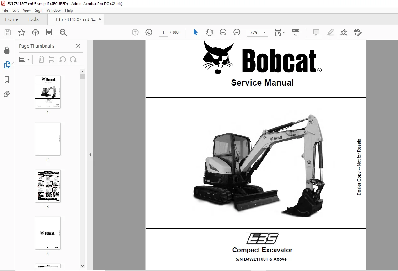
S/N B3WZ11001 & Above
Description
Bobcat E35 Compact Excavator Service Manual SN B3WZ11001 & Above – PDF DOWNLOAD
FILE DETAILS:
Bobcat E35 Compact Excavator Service Manual SN B3WZ11001 & Above – PDF DOWNLOAD
Language : English
Pages : 993
Downloadable : Yes
File Type : PDF
DESCRIPTION:
Bobcat E35 Compact Excavator Service Manual SN B3WZ11001 & Above – PDF DOWNLOAD
S/N B3WZ11001 & Above
IMAGES PREVIEW OF THE MANUAL:
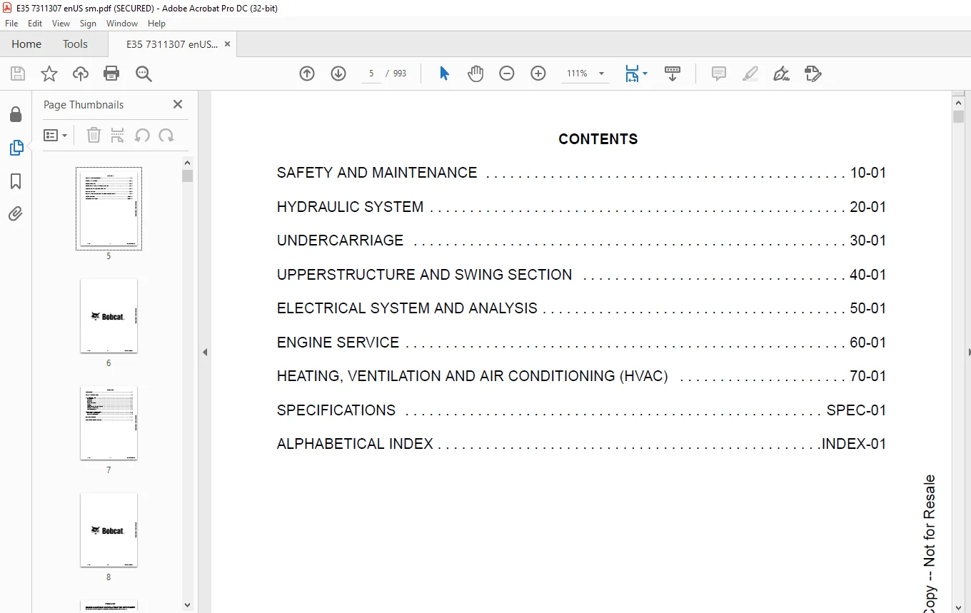
TABLE OF CONTENTS:
Bobcat E35 Compact Excavator Service Manual SN B3WZ11001 & Above – PDF DOWNLOAD
MAINTENANCE SAFETY 3
CONTENTS 5
FOREWORD 7
FOREWORD 9
SAFETY INSTRUCTIONS 11
FIRE PREVENTION 13
Maintenance 13
Operation 13
Electrical 13
Hydraulic System 13
Fueling 13
Starting 13
Spark Arrester Exhaust System 13
Welding And Grinding 14
Fire Extinguishers 14
SERIAL NUMBER LOCATIONS 15
Excavator Serial Number 15
Engine Serial Number 15
DELIVERY REPORT 16
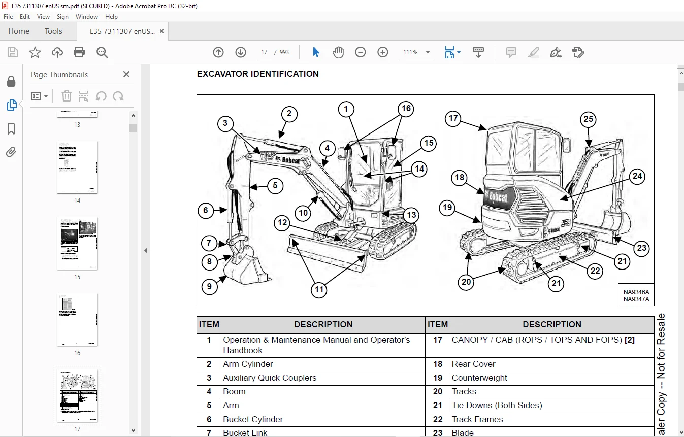
EXCAVATOR IDENTIFICATION 17
SAFETY AND MAINTENANCE 19
LIFTING AND BLOCKING THE EXCAVATOR 23
Procedure 23
LIFTING THE EXCAVATOR 25
Procedure 25
OPERATOR CAB (ROPS / TOPS) 27
Description 27
Cab Door 28
Front Window 29
Front Wiper 30
Window Washer Reservoir 30
Right Side Window 31
OPERATOR CANOPY (ROPS / TOPS) 33
Description 33
TRANSPORTING THE EXCAVATOR ON A TRAILER 35
Loading And Unloading 35
Fastening 35
TAILGATE 37
Opening And Closing 37
Adjusting The Latch 37
RIGHT SIDE COVER 39
Opening And Closing 39
SERVICE SCHEDULE 41
Maintenance Intervals 41
AIR CLEANER SERVICE 43
Daily Check 43
Replacing The Filters 43
CAB FILTERS 47
Cleaning And Maintenance 47
ENGINE COOLING SYSTEM 49
Cleaning 49
Checking Level 50
Removing And Replacing Coolant 51
FUEL SYSTEM 53
Fuel Specifications 53
Biodiesel Blend Fuel 53
Filling The Fuel Tank 54
Fuel Filters 55
Removing Air From The Fuel System 56
Draining The Fuel Tank 56
ENGINE LUBRICATION SYSTEM 57
Checking And Adding Engine Oil 57
Engine Oil Chart 57
Removing And Replacing Oil And Filter 58
HYDRAULIC SYSTEM 59
Checking And Adding Hydraulic Fluid 59
Hydraulic / Hydrostatic Fluid Chart 60
Removing And Replacing Hydraulic Filters 60
Removing And Replacing Hydraulic Fluid 62
LUBRICATING THE EXCAVATOR 65
Lubrication Locations 65
PIVOT PINS 69
Inspection And Maintenance 69
TRAVEL MOTOR 71
Checking And Adding Oil 71
Removing And Replacing Oil 71
EMERGENCY EXIT 73
Right Side Rear Window 73
Front Window 73
SEAT BELT 75
Inspection And Maintenance 75
CONTROL CONSOLE LOCKOUTS 77
Inspection And Maintenance 77
TOWING THE EXCAVATOR 79
Procedure 79
REMOTE START TOOL KIT – MEL1563 81
Remote Start Tool Kit – MEL1563 81
Service Tool Harness Control – MEL1565 82
Service Tool Harness Communicator – MEL1566 83
REMOTE START TOOL (SERVICE TOOL) KIT – 7217666 85
Description 85
Remote Start Tool (Service Tool) – 7022042 86
Excavator Service Tool Harness – 6689747 87
Computer Service Tool Harness – 6689746 88
HYDRAULIC SYSTEM 89
HYDRAULIC / HYDROSTATIC SCHEMATICS 95
HYDRAULIC SYSTEM INFORMATION 97
Glossary Of Hydraulic / Hydrostatic Symbols 97
Troubleshooting The Hydraulic Circuit 100
Troubleshooting The Cylinder Circuit 101
Troubleshooting The Swing (Upperstructure Slew) Circuit 102
Troubleshooting The Travel Circuit 103
CYLINDER (BOOM) 105
Testing 105
Removal And Installation 107
Parts Identification 110
Disassembly 111
Assembly 114
CYLINDER (ARM) 119
Testing 119
Removal And Installation 121
Parts Identification 123
Disassembly 124
Assembly 126
CYLINDER (BOOM SWING) 131
Testing 131
Removal And Installation 133
Parts Identification 135
Disassembly 136
Assembly 138
CYLINDER (BUCKET) 143
Testing 143
Removal And Installation 144
Parts Identification 146
Disassembly 147
Assembly 149
CYLINDER (BLADE) 153
Testing 153
Removal And Installation 155
Parts Identification 156
Disassembly 157
Assembly 159
CYLINDER (CLAMP) 163
Testing 163
Removal And Installation 164
Parts Identification 166
Disassembly 167
Assembly 170
CYLINDER (ANGLE BLADE) 175
Testing 175
Removal And Installation 176
Parts Identification 178
Disassembly 179
Assembly 181
CYLINDER (EXTENDABLE ARM) 185
Testing 185
Parts Identification 187
Disassembly 188
Assembly 191
VALVE (MAIN RELIEF) 195
Description 195
VALVE (PORT RELIEF) 197
Testing And Adjusting Port Relief Valve Pressure 197
VALVE (CROSS PORT RELIEF) 199
Testing 199
Removal And Installation 201
Disassembly And Assembly 201
VALVE (PILOT PRESSURE RELIEF) 203
Testing And Adjusting The Pilot Pressure Relief Valve 203
HYDRAULIC CONTROL VALVE 205
Description 205
Removal And Installation 205
Parts Identification 209
Disassembly 210
Assembly 216
Inlet Valve Section Disassembly And Assembly 219
Boom Swing Valve Section Disassembly And Assembly 221
Slew Valve Section Disassembly And Assembly 224
Blade Valve Section Disassembly And Assembly 225
Right And Left Travel Valve Section Disassembly And Assembly 228
Boom Valve Section Disassembly And Assembly 230
Auxiliary, Arm, Bucket And Angle Blade Valve Section Disassembly And Assembly 234
Outlet Valve Section Disassembly And Assembly 236
HYDRAULIC PUMP 239
Hydraulic Pump Work Sheet 239
Pump Testing 241
Description 249
Removal And Installation 249
Coupler Removal And Installation 250
Hydraulic Pump Startup 251
Gear Pump Disassembly And Assembly 252
Piston Pump Parts Identification 254
Piston Pump Disassembly And Assembly 255
MANIFOLD ASSEMBLY / ACCUMULATOR (WITHOUT ANGLE BLADE) 267
Description 267
Removal And Installation 267
Parts Identification 269
Disassembly And Assembly 270
MANIFOLD ASSEMBLY / ACCUMULATOR (WITH ANGLE BLADE) 277
Description 277
Removal And Installation 277
Parts Identification 279
Disassembly And Assembly 280
TRAVEL MOTOR 287
Description 287
Removal And Installation 287
Parts Identification Hydraulic Motor 288
Parts Identification Gear Reduction Hub 289
Disassembly 290
Assembly 304
SWIVEL JOINT (LATER MODELS) 319
Removal And Installation 319
Parts Identification Angle Blade Swivel 321
Parts Identification Straight Blade Swivel 322
Disassembly And Assembly 323
SWIVEL JOINT (EARLIER MODELS) 327
Removal And Installation 327
Parts Identification Angle Blade Swivel 329
Parts Identification Straight Blade Swivel 330
Disassembly And Assembly 331
SWING MOTOR 333
Removal And Installation 333
Parts Identification 334
Disassembly And Assembly 335
SWING MOTOR (DRIVE CARRIER) 341
Removal And Installation 341
Parts Identification 342
Disassembly And Assembly 343
CONTROL PATTERN SELECTOR VALVE 349
Removal And Installation 349
Parts Identification 350
Disassembly And Assembly 351
RIGHT CONTROL LEVER (JOYSTICK) 353
Testing 353
Handle Removal And Installation 354
Joystick Assembly Removal And Installation 356
Parts Identification 357
Disassembly 358
Assembly 363
LEFT CONTROL LEVER (JOYSTICK) 369
Testing 369
Handle Removal And Installation 370
Joystick Assembly Removal And Installation 372
Parts Identification 373
Disassembly 374
Assembly 379
HYDRAULIC FILTER MOUNT 385
Removal And Installation 385
HYDRAULIC RESERVOIR 387
Removal And Installation 387
OIL COOLER 389
Removal And Installation 389
DIRECT TO TANK VALVE 391
Removal And Installation 391
BLADE CONTROL LEVER 393
Handle Removal And Installation 393
Removal And Installation 395
Parts Identification 396
Disassembly And Assembly 397
CASE DRAIN FILTER MOUNT 401
Removal And Installation 401
TRAVEL CONTROL VALVE 403
Removal And Installation 403
Parts Identification 404
Disassembly And Assembly 405
REMOVING AIR FROM THE HYDRAULIC SYSTEM 411
Procedure 411
HYDRAULIC X-CHANGE MANIFOLD (EARLIER MODELS) 413
Removal And Installation 413
Parts Identification 414
Disassembly And Assembly 415
HYDRAULIC X-CHANGE MANIFOLD (LATER MODELS) 421
Removal And Installation 421
Parts Identification 422
Disassembly And Assembly 423
SECONDARY AUXILIARY VALVE 429
Removal And Installation 429
Parts Identification 431
Disassembly And Assembly 432
VALVE (BOOM LOCK) 435
Removal And Installation 435
VALVE (ARM LOCK) 437
Removal And Installation 437
UNDERCARRIAGE 439
BLADE 441
Removal And Installation 441
BLADE (ANGLE) 443
Removal And Installation 443
Cutting Edge Removal And Installation 444
TRACK UNDERCARRIAGE COMPONENTS (RUBBER TRACK) 445
Description 445
Track Lug Height 445
Checking Tension 446
Adjusting Tension 448
Removal And Installation 449
Idler Removal And Installation 451
Idler Parts Identification 452
Idler Disassembly 453
Idler Assembly 455
Track Tensioner Removal And Installation 458
Track Tensioner Parts Identification 459
Track Tensioner Disassembly And Assembly 460
Roller Removal And Installation 462
Sprocket Removal And Installation 462
TRACK UNDERCARRIAGE COMPONENTS (STEEL TRACK) 463
Description 463
Checking Tension 464
Adjusting Tension 466
Track Removal And Installation 467
Idler Removal And Installation 470
Idler Parts Identification 471
Idler Disassembly 472
Idler Assembly 474
Track Tensioner Removal And Installation 477
Track Tensioner Cylinder Parts Identification 478
Track Tensioner Disassembly And Assembly 479
Roller Removal And Installation 481
Sprocket Removal And Installation 482
Guide Plate Removal And Installation 482
TRACK MAINTENANCE 483
Track Damage Identification 483
SWING CIRCLE GEAR 495
Swing Bearing Removal 495
Swing Bearing Installation 496
UPPERSTRUCTURE AND SWING SECTION 497
UPPERSTRUCTURE 501
Removal 501
Installation 503
ROPS CANOPY 505
Removal And Installation 505
CAB 509
Removal And Installation 509
Door Removal And Installation 512
Front Window Removal And Installation 513
Front Window Disassembly And Assembly 514
Front Window Adjustment 516
Glass Removal 518
Glass Installation 519
SEAT 525
Removal And Installation 525
RIGHT CONSOLE 527
Console Cover Removal And Installation 527
LEFT CONSOLE 531
Lower Console Cover Removal And Installation 531
Upper Console Cover Removal And Installation 532
Compression Spring Removal And Installation 535
Lock Lever Removal And Installation 537
Console Removal And Installation 537
LEFT UPPERSTRUCTURE COVER 539
Removal And Installation 539
RIGHT UPPERSTRUCTURE COVER 541
Removal And Installation 541
COUNTERWEIGHT 543
Removal And Installation 543
Add On Counterweight Removal And Installation 547
TRAVEL LEVERS AND PEDALS 549
Removal And Installation 549
Disassembly And Assembly 549
FLOOR MAT 551
Removal And Installation 551
FUEL TANK 553
Removal And Installation 553
Fuel Tank Fitting Removal And Installation 554
HORN 555
Removal And Installation 555
SWING FRAME 557
Removal And Installation 557
Boom Swing Frame Hose Routing 560
Bushing Removal 561
Bushing Installation 562
BOOM 563
Removal And Installation 563
ARM (STANDARD AND LONG) 565
Removal And Installation 565
Arm To Boom Bushing Removal And Installation 566
Arm To Bucket And Bucket Link Bushing Removal And Installation 567
ARM (EXTENDABLE) 569
Removal And Installation 569
Arm To Boom Bushing Removal And Installation 570
Arm To Bucket Bushing Removal And Installation 571
Disassembly And Assembly 572
Shimming Procedure 580
BUCKET 581
Bucket Teeth Removal And Installation 581
Bucket Side Cutting Edge Removal And Installation 582
CLAMP 583
Removal And Installation 583
TAILGATE 585
Removal And Installation 585
Disassembly And Assembly 586
X-CHANGE 589
Removal And Installation 589
Disassembly 590
Assembly 591
X-CHANGE (HYDRAULIC) (EARLIER MODELS) 593
Removal And Installation 593
Parts Identification 595
Disassembly 596
Assembly 601
X-CHANGE (HYDRAULIC) (LATER MODELS) 609
Removal And Installation 609
Parts Identification 611
Disassembly 612
Assembly 618
Expansion Plug Installation 626
QUICK COUPLER (KLAC™ SYSTEM) 627
Troubleshooting 627
Daily Inspection 627
Removal And Installation 628
Parts Identification 630
Disassembly 631
Assembly 633
QUICK COUPLER (LEHNHOFF® SYSTEM) 635
Troubleshooting 635
Daily Inspection 635
Removal (MS03 And MS08) 636
Installation (MS03 And MS08) 637
Parts Identification (MS03) 638
Disassembly And Assembly (MS03) 639
Parts Identification (MS08) 640
Disassembly (MS08) 641
Assembly (MS08) 645
QUICK COUPLER (PIN GRABBER) 649
Troubleshooting 649
Daily Inspection 650
Removal And Installation 651
Parts Identification 652
Disassembly And Assembly 653
RIGHT SIDE COVER 657
Removal And Installation 657
Latch Removal And Installation 657
LEFT SIDE COVER 659
Removal And Installation 659
TOOL BOX 661
Removal And Installation 661
ELECTRICAL SYSTEM AND ANALYSIS 663
ELECTRICAL SCHEMATICS 665
ELECTRICAL SYSTEM INFORMATION 700
Troubleshooting Chart 700
Description 701
Fuse And Relay Location / Identification 701
BATTERY 704
Servicing 704
Maintaining Battery Charge Level 704
Battery Service During Machine Storage 704
Battery Testing 705
Battery Charging 705
Removal And Installation 706
Using A Booster Battery (Jump Starting) 707
ALTERNATOR 708
Belt Adjustment 708
Belt Replacement 708
Charging System Inspection 709
Alternator Voltage Testing 710
Low Voltage Testing 710
High Voltage Testing 711
Removal And Installation 712
Parts Identification 714
STARTER 716
Testing 716
Removal And Installation 717
Parts Identification 718
LIGHTS 720
Removal And Installation 720
Boom Light Removal And Installation 721
Boom Light Bulb Replacement 721
MAGNETIC LOCKOUT SENSOR 722
Removal And Installation 722
FUEL LEVEL SENDER 724
Removal And Installation 724
Testing 725
DIAGNOSTIC SERVICE CODES 726
Viewing Service Codes 726
Service Codes List 727
CONTROL PANEL SETUP 734
Panel Setup (Deluxe Instrument Panel) 734
Password Setup (Keyless Start Panel) 740
Password Setup (Deluxe Instrument Panel) 741
Maintenance Clock 743
INSTRUMENT PANEL 748
Removal And Installation 748
CONTROLLER 750
Description 750
Auxiliary Controller Removal And Installation 750
Gateway Controller Removal And Installation 752
KEY SWITCH 754
Removal And Installation 754
WIPER MOTOR 756
Removal And Installation 756
MOTION ALARM SYSTEM 758
Description 758
Inspecting 758
Adjusting Switch Position 759
SERVICE PC (LAPTOP COMPUTER) 760
Connecting The Remote Start Tool 760
Connecting Remote Start Tool (Service Tool) 760
SHUT-OFF SWITCH 762
Description 762
Removal And Installation 763
TRAVEL MOTOR AUTO-SHIFT 764
Auto-Shift Drive System (If Equipped) 764
Troubleshooting 765
ENGINE SPEED CONTROL 766
Removal And Installation 766
AUTO IDLE PRESSURE SENSOR 768
Description 768
Removal And Installation 769
BOBCAT MACHINE IQ WIRELESS COMMUNICATIONS 770
Description 770
Controller Removal And Installation 770
Antenna Removal And Installation 773
Procedure 774
ENGINE SERVICE 776
ENGINE INFORMATION 780
Description 780
Specifications 781
Sensor Location 783
Torque Values 789
Troubleshooting 791
Engine Removal And Installation 793
Compression – Testing 801
Injector Signal – Testing 803
DIESEL OXIDATION CATALYST (DOC) 806
Removal And Installation 806
AIR CLEANER 808
Housing Removal And Installation 808
ENGINE COOLING SYSTEM 810
Radiator Removal And Installation 810
Fan Removal And Installation 814
Water Pump Removal And Installation 815
Thermostat Housing Removal And Installation 816
Testing The Thermostat 817
FUEL SYSTEM 818
Description 818
Transfer Pump / High Pressure Pump Removal And Installation 819
Fuel Cooler Removal And Installation 823
Fuel Bypass Valve Removal And Installation 824
Fuel Recirculation Valve Removal and Installation 825
Fuel Injector Removal And Installation 826
Injector Coding 828
Removing Air From The Fuel System 830
LUBRICATION SYSTEM 832
Description 832
Oil Pan Removal And Installation 833
Oil Pump Removal And Installation 834
Oil Pump Relief Valve Description 834
Oil Pump Relief Valve Removal And Installation 834
Oil Cooler Removal And Installation 835
Oil Filter Head Removal And Installation 835
Oil Cooler Bypass Description 836
Oil Cooler Bypass Removal And Installation 836
CYLINDER HEAD 838
Glow Plugs Testing 838
Glow Plug Removal And Installation 839
Valve Clearance Adjustment 840
Cylinder Head Removal And Installation 842
Cylinder Head Disassembly And Assembly 846
Cylinder Head Inspection 847
Cylinder Head Top Clearance 848
Valve Step Height 849
Valve Stem Height 849
Valve Guide 850
Valve 850
Valve Spring 851
Rocker Arm Shaft Disassembly And Assembly 852
Rocker Arm Shaft Inspection 853
Push Rod Inspection 853
CRANKSHAFT AND PISTONS 854
Piston And Connecting Rod Removal And Installation 854
Piston And Connecting Rod Inspection 855
Crankshaft Removal And Installation 857
Cylinder Block Inspection 860
Crankshaft Inspection 862
Connecting Rod Inspection 862
Engine Component Class 863
CAMSHAFT 866
Removal And Installation 866
Inspecting 867
GEARCASE 870
Gearcase Cover Removal And Installation 870
Gear Backlash 871
Gear Timing 872
Idle Gear Removal And Installation 873
Idle Gear Inspection 873
TURBOCHARGER 874
Description 874
Removal And Installation 874
Inspection 876
FLYWHEEL AND HOUSING 878
Hydraulic Pump Coupler Removal And Installation 878
Flywheel Removal And Installation 880
Ring Gear Removal And Installation 880
EXHAUST GAS RECIRCULATION (EGR) SYSTEM 882
Valve Removal And Installation 882
Cooler Removal And Installation 882
INTERCOOLER 884
Description 884
Removal And Installation 884
HEATING, VENTILATION AND AIR CONDITIONING (HVAC) 886
AIR CONDITIONING SYSTEM FLOW 888
Description 888
Chart 889
Components 890
Safety Equipment 893
REGULAR MAINTENANCE 894
Cab Filters 894
Air Conditioning Compressor Belt Adjustment 895
Air Conditioning Compressor Belt Replacement 895
Condenser 896
Air Conditioning Lubrication 896
Evaporator / Heater Coil 896
Air Conditioning Service Chart 898
TROUBLESHOOTING 900
Blower Motor Does Not Operate 900
Blower Motor Operates Normally, But Air Flow Is Insufficient 900
Insufficient Cooling Although Air Flow And Compressor Operation Are Normal 900
The Compressor Operates Improperly Or Not At All 900
Gauge Pressure Related Troubleshooting 901
Temperature / Pressure Chart 902
Poor A/C Performance 903
HVAC Repair And Leaks 903
Electrical System 904
Engine Coolant Bypassing The Heater Valve 906
SYSTEM CHARGING AND RECLAMATION 908
Refrigerant Identification 908
Reclamation And Charging With Recovery / Charging Unit 910
COMPRESSOR 912
Removal And Installation 912
Oil 913
Oil Check 914
CONDENSER 916
Removal And Installation 916
RECEIVER / DRIER 918
Receiver / Drier Removal And Installation 918
Pressure Switch Removal And Installation 919
EVAPORATOR / HEATER UNIT 920
Removal And Installation 920
THERMOSTAT 924
Description 924
Removal And Installation 925
EXPANSION VALVE 928
Removal And Installation 928
EVAPORATOR COIL 930
Removal And Installation 930
HEATER COIL 932
Removal And Installation 932
BLOWER FAN 934
Removal And Installation 934
HEATER VALVE 936
Removal And Installation 936
HVAC DUCT 938
Removal And Installation 938
AUTO HVAC 940
Description 940
ATM Removal And Installation 940
ATM Diagnostic Codes 941
Blower Fan Drive Assembly Removal And Installation 942
De-Icing Sensor Removal And Installation 943
Inside And After Coil Sensor Testing 943
SPECIFICATIONS 946
EXCAVATOR SPECIFICATIONS 948
Machine Dimensions 948
Machine Dimensions – Standard Arm 949
Machine Dimensions – Long Arm 950
Machine Dimensions – Extendable Arm 951
Machine Dimensions – Angle Blade 952
Rated Lift Capacity – Standard Arm 953
Rated Lift Capacity – Standard Arm With Additional Counterweight 954
Rated Lift Capacity – Long Arm 955
Rated Lift Capacity – Extendable Arm 956
Performance 957
Engine 957
Controls 958
Hydraulic System 959
Hydraulic Cylinders 960
Hydraulic Cycle Times 960
Drive System 961
Slew System 961
Undercarriage 961
Electrical 961
Capacities 962
Tracks 962
Ground Pressure 962
TECHNICAL SERVICE GUIDE SPECIFICATIONS 964
Engine 964
Engine Torques 964
Cooling System 964
Excavator Torques 964
TORQUE SPECIFICATION FOR BOLTS 966
Torque For General SAE Bolts 966
Torque For General Metric Bolts 967
HYDRAULIC CONNECTION SPECIFICATIONS 968
O-ring Face Seal Connection 968
Straight Thread O-ring Fitting 968
Tubelines And Hoses 969
Flare Fitting 969
O-ring Flare Fitting 970
Port Seal Fitting 972
Push To Connect Fittings 973
HYDRAULIC FLUID SPECIFICATIONS 976
Specifications 976
CONVERSIONS 978
Decimal And Millimeter Equivalent Chart 978
U S To Metric Conversion Chart 979
SERVICE TOOLS REQUIRED 980
Remote Start Tools 980
Hydraulic Tools 981
Engine Tools 984
Electrical Tools 986
General Tools 986
HVAC Tools 987
ALPHABETICAL INDEX 988
SERVICE SCHEDULE SYMBOLS 992
Questions? Email us: [email protected]
https://vimeo.com/841776137?share=copy
PLEASE NOTE:
- This is the SAME exact manual used by your dealers to fix your vehicle.
- The same can be yours in the next 2-3 mins as you will be directed to the download page immediately after paying for the manual.
- Any queries / doubts regarding your purchase, please feel free to contact [email protected]
S.M