Bobcat E35 Compact Excavator Service Manual SNB3Y211001 & Above – PDF DOWNLOAD
$34.95
Bobcat E35 Compact Excavator Service Manual SNB3Y211001 & Above – PDF DOWNLOAD
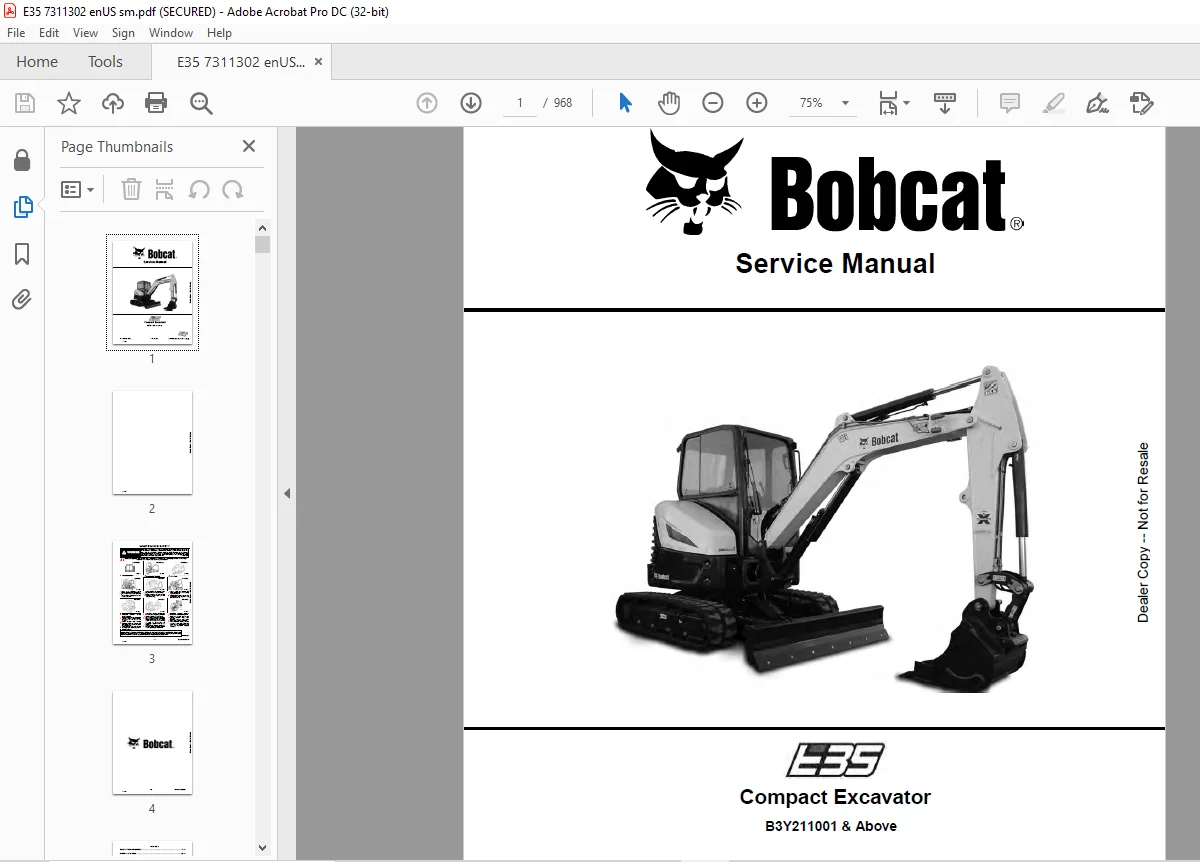
B3Y211001 & Above
Description
Bobcat E35 Compact Excavator Service Manual SNB3Y211001 & Above – PDF DOWNLOAD
FILE DETAILS:
Bobcat E35 Compact Excavator Service Manual SNB3Y211001 & Above – PDF DOWNLOAD
Language : English
Pages : 968
Downloadable : Yes
File Type : PDF
DESCRIPTION:
B3Y211001 & Above
Bobcat E35 Compact Excavator Service Manual SNB3Y211001 & Above – PDF DOWNLOAD
FOREWORD
This manual is for the Bobcat excavator mechanic. It provides necessary servicing and adjustment procedures for the Bobcat excavator and its component parts and systems. Refer to the Operation & Maintenance Manual for operating instructions, starting procedure, daily checks, etc.
SAFETY INSTRUCTIONS
Instructions are necessary before operating or servicing machine. Read and understand the Operation & Maintenance Manual, Operator’s Handbook and signs (decals) on machine. Follow warnings and instructions in the manuals when making repairs, adjustments or servicing. Check for correct function after adjustments, repairs or service. Untrained operators and failure to follow instructions can cause injury or death.
The following publications provide information on the safe use and maintenance of the Bobcat machine and attachments:
- The Delivery Report is used to assure that complete instructions have been given to the new owner and that the machine is in safe operating condition.
- The Operation & Maintenance Manual delivered with the machine or attachment contains operating information as well as routine maintenance and service procedures. It is a part of the machine and can be stored in a container provided on the machine. Replacement Operation & Maintenance Manuals can be ordered from your Bobcat dealer.
- Machine signs (decals) instruct on the safe operation and care of your Bobcat machine or attachment. The signs and their locations are shown in the Operation & Maintenance Manual. Replacement signs are available from your Bobcat dealer.
- An Operator’s Handbook fastened to the operator cab. It’s brief instructions are convenient to the operator. The handbook is available from your dealer in an English edition or one of many other languages. See your Bobcat dealer for more information on translated versions.
- The AEM Safety Manual delivered with the machine gives general safety information.
- The Service Manual and Parts Manual are available from your dealer for use by mechanics to do shoptype service and repair work.
IMAGES PREVIEW OF THE MANUAL:
TABLE OF CONTENTS:
Bobcat E35 Compact Excavator Service Manual SNB3Y211001 & Above – PDF DOWNLOAD
MAINTENANCE SAFETY 3
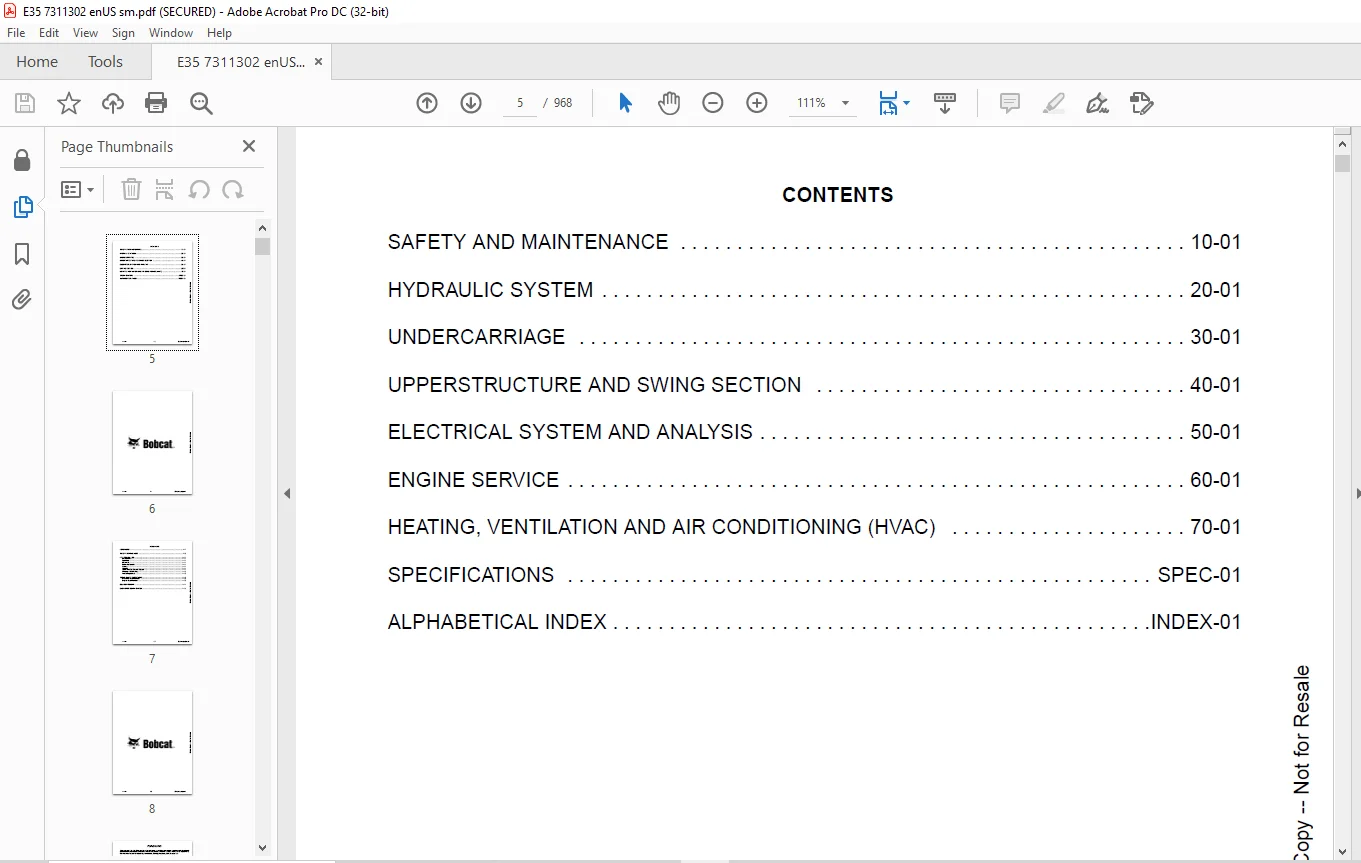
CONTENTS 5
FOREWORD 7
FOREWORD 9
SAFETY INSTRUCTIONS 11
FIRE PREVENTION 13
Maintenance 13
Operation 13
Electrical 13
Hydraulic System 13
Fueling 13
Starting 13
Spark Arrester Exhaust System 13
Welding And Grinding 14
Fire Extinguishers 14
SERIAL NUMBER LOCATIONS 15
Excavator Serial Number 15
Engine Serial Number 15
DELIVERY REPORT 16
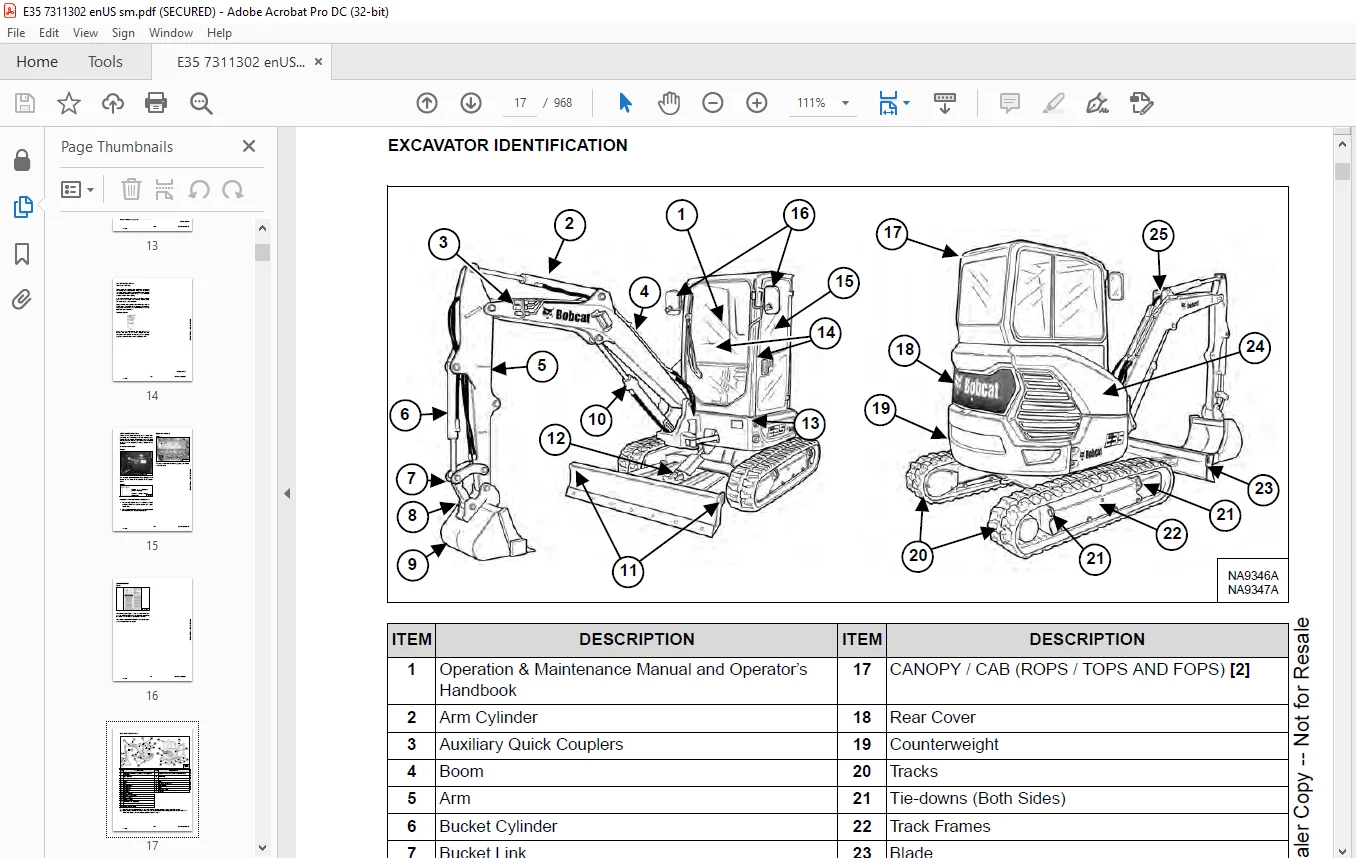
EXCAVATOR IDENTIFICATION 17
SAFETY AND MAINTENANCE 19
LIFTING AND BLOCKING THE EXCAVATOR 23
Procedure 23
LIFTING THE EXCAVATOR 25
Procedure 25
OPERATOR CAB (ROPS / TOPS) 27
Description 27
Cab Door 28
Front Window 29
Front Wiper 30
Window Washer Reservoir 30
Right Side Windows 31
OPERATOR CANOPY (ROPS / TOPS) 33
Description 33
TRANSPORTING THE EXCAVATOR ON A TRAILER 35
Loading And Unloading 35
Fastening 35
TAILGATE 37
Opening And Closing 37
Adjusting The Latch 37
RIGHT SIDE COVER 39
Opening And Closing 39
SERVICE SCHEDULE 41
Maintenance Intervals 41
AIR CLEANER SERVICE 43
Daily Check 43
Replacing The Filter Elements 43
CAB FILTERS 45
Cleaning And Maintenance 45
ENGINE COOLING SYSTEM 47
Cleaning 47
Checking Level 49
Removing And Replacing Coolant 50
FUEL SYSTEM 51
Fuel Specifications 51
Biodiesel Blend Fuel 51
Filling The Fuel Tank 52
Fuel Filters 53
Draining The Fuel Tank 53
Removing Air From The Fuel System 54
ENGINE LUBRICATION SYSTEM 55
Checking And Adding Engine Oil 55
Engine Oil Chart 55
Removing And Replacing Oil And Filter 56
HYDRAULIC SYSTEM 57
Checking And Adding Hydraulic Fluid 57
Hydraulic / Hydrostatic Fluid Chart 58
Removing And Replacing Hydraulic Filters 59
Removing And Replacing Hydraulic Fluid 60
LUBRICATING THE EXCAVATOR 63
Lubrication Locations 63
PIVOT PINS 67
Inspection And Maintenance 67
TRAVEL MOTOR 69
Checking And Adding Oil 69
Removing And Replacing Oil 69
SPARK ARRESTER MUFFLER 71
Cleaning Procedure 71
EMERGENCY EXIT 73
Right Side Rear Window 73
Front Window 73
SEAT BELT 75
Inspection And Maintenance 75
CONTROL CONSOLE LOCKOUTS 77
Inspection And Maintenance 77
TOWING THE EXCAVATOR 79
Procedure 79
REMOTE START TOOL KIT – MEL1563 81
Remote Start Tool Kit – MEL1563 81
Service Tool Harness Control – MEL1565 82
Service Tool Harness Communicator – MEL1566 83
REMOTE START TOOL (SERVICE TOOL) KIT – 7217666 85
Description 85
Remote Start Tool (Service Tool) – 7022042 86
Excavator Service Tool Harness – 6689747 87
Computer Service Tool Harness – 6689746 88
HYDRAULIC SYSTEM 89
HYDRAULIC / HYDROSTATIC SCHEMATICS 95
HYDRAULIC SYSTEM INFORMATION 97
Glossary Of Hydraulic / Hydrostatic Symbols 97
Troubleshooting The Hydraulic Circuit 100
Troubleshooting The Cylinder Circuit 101
Troubleshooting The Swing (Upperstructure Slew) Circuit 102
Troubleshooting The Travel Circuit 103
CYLINDER (BOOM) 105
Testing 105
Removal And Installation 107
Parts Identification 110
Disassembly 111
Assembly 114
CYLINDER (ARM) 119
Testing 119
Removal And Installation 121
Parts Identification 123
Disassembly 124
Assembly 126
CYLINDER (BOOM SWING) 131
Testing 131
Removal And Installation 133
Parts Identification 135
Disassembly 136
Assembly 138
CYLINDER (BUCKET) 143
Testing 143
Removal And Installation 144
Parts Identification 146
Disassembly 147
Assembly 149
CYLINDER (BLADE) 153
Testing 153
Removal And Installation 155
Parts Identification 156
Disassembly 157
Assembly 159
CYLINDER (CLAMP) 163
Testing 163
Removal And Installation 164
Parts Identification 166
Disassembly 167
Assembly 170
CYLINDER (ANGLE BLADE) 175
Testing 175
Removal And Installation 176
Parts Identification 178
Disassembly 179
Assembly 181
CYLINDER (EXTENDABLE ARM) 185
Testing 185
Parts Identification 187
Disassembly 188
Assembly 191
VALVE (MAIN RELIEF) 195
Description 195
VALVE (PORT RELIEF) 197
Testing And Adjusting Port Relief Valve Pressure 197
VALVE (CROSS PORT RELIEF) 199
Testing 199
Removal And Installation 201
Disassembly And Assembly 201
VALVE (PILOT PRESSURE RELIEF) 203
Testing And Adjusting The Pilot Pressure Relief Valve 203
HYDRAULIC CONTROL VALVE 205
Description 205
Removal And Installation 205
Parts Identification 210
Disassembly 211
Assembly 217
Inlet Valve Section Disassembly And Assembly 221
Boom Swing Valve Section Disassembly And Assembly 223
Slew Valve Section Disassembly And Assembly 225
Blade Valve Section Disassembly And Assembly 226
Right And Left Travel Valve Section Disassembly And Assembly 229
Boom Valve Section Disassembly And Assembly 231
Auxiliary, Arm, Bucket And Angle Blade Valve Section Disassembly And Assembly 235
Outlet Valve Section Disassembly And Assembly 237
HYDRAULIC PUMP 239
Hydraulic Pump Work Sheet 239
Pump Testing 241
Description 249
Removal And Installation 249
Coupler Removal And Installation 250
Hydraulic Pump Startup 251
Gear Pump Disassembly And Assembly 252
Piston Pump Parts Identification 254
Piston Pump Disassembly And Assembly 255
MANIFOLD ASSEMBLY / ACCUMULATOR (WITHOUT ANGLE BLADE) 267
Description 267
Removal And Installation 267
Parts Identification 269
Disassembly And Assembly 270
MANIFOLD ASSEMBLY / ACCUMULATOR (WITH ANGLE BLADE) 277
Description 277
Removal And Installation 277
Parts Identification 279
Disassembly And Assembly 280
TRAVEL MOTOR 287
Description 287
Removal And Installation 287
Parts Identification Hydraulic Motor 288
Parts Identification Gear Reduction Hub 289
Disassembly 290
Assembly 304
SWIVEL JOINT (LATER MODELS) 321
Removal And Installation 321
Parts Identification Angle Blade Swivel 323
Parts Identification Straight Blade Swivel 324
Disassembly And Assembly 325
SWIVEL JOINT (EARLIER MODELS) 329
Removal And Installation 329
Parts Identification 331
Disassembly And Assembly 332
SWING MOTOR 335
Removal And Installation 335
Parts Identification 336
Disassembly And Assembly 337
SWING MOTOR (DRIVE CARRIER) 343
Removal And Installation 343
Parts Identification 344
Disassembly And Assembly 345
CONTROL PATTERN SELECTOR VALVE 351
Removal And Installation 351
Parts Identification 352
Disassembly And Assembly 353
RIGHT CONTROL LEVER (JOYSTICK) 355
Testing 355
Handle Removal And Installation 356
Joystick Assembly Removal And Installation 358
Parts Identification 359
Disassembly 360
Assembly 365
LEFT CONTROL LEVER (JOYSTICK) 371
Testing 371
Handle Removal And Installation 372
Joystick Assembly Removal And Installation 374
Parts Identification 375
Disassembly 376
Assembly 381
HYDRAULIC FILTER MOUNT 387
Removal And Installation 387
HYDRAULIC RESERVOIR 389
Removal And Installation 389
OIL COOLER 391
Removal And Installation 391
DIRECT TO TANK VALVE 393
Removal And Installation 393
BLADE CONTROL LEVER 395
Handle Removal And Installation 395
Removal And Installation 397
Parts Identification 398
Disassembly And Assembly 399
CASE DRAIN FILTER MOUNT 403
Removal And Installation 403
TRAVEL CONTROL VALVE 405
Removal And Installation 405
Parts Identification 406
Disassembly And Assembly 407
REMOVING AIR FROM THE HYDRAULIC SYSTEM 413
Procedure 413
HYDRAULIC X-CHANGE MANIFOLD 415
Removal And Installation 415
Parts Identification 416
Disassembly And Assembly 417
SECONDARY AUXILIARY VALVE 423
Removal And Installation 423
Parts Identification 425
Disassembly And Assembly 426
VALVE (BOOM LOCK) 429
Removal And Installation 429
VALVE (ARM LOCK) 431
Removal And Installation 431
UNDERCARRIAGE 433
BLADE 435
Removal And Installation 435
BLADE (ANGLE) 437
Removal And Installation 437
Cutting Edge Removal And Installation 438
TRACK UNDERCARRIAGE COMPONENTS (RUBBER TRACK) 439
Description 439
Track Lug Height 439
Checking Tension 440
Adjusting Tension 442
Removal And Installation 443
Idler Removal And Installation 445
Parts Identification 446
Idler Disassembly 447
Idler Assembly 449
Track Tensioner Removal And Installation 452
Track Tensioner Parts Identification 453
Track Tensioner Disassembly And Assembly 454
Roller Removal And Installation 456
Sprocket Removal And Installation 457
TRACK UNDERCARRIAGE COMPONENTS (STEEL TRACK) 459
Description 459
Checking Tension 460
Adjusting Tension 462
Track Removal And Installation 464
Idler Removal And Installation 467
Idler Parts Identification 468
Idler Disassembly 469
Idler Assembly 471
Track Tensioner Disassembly And Assembly 474
Track Tensioner Parts Identification 475
Track Tensioner Disassembly And Assembly 476
Roller Removal And Installation 478
Sprocket Removal And Installation 479
Guide Plate Removal And Installation 479
TRACK MAINTENANCE 481
Track Damage Identification 481
SWING CIRCLE GEAR 493
Swing Bearing Removal 493
Swing Bearing Installation 494
UPPERSTRUCTURE AND SWING SECTION 495
UPPERSTRUCTURE 499
Removal 499
Installation 501
ROPS CANOPY 503
Removal And Installation 503
CAB 507
Removal And Installation 507
Door Removal And Installation 510
Front Window Removal And Installation 511
Front Window Disassembly And Assembly 512
Front Window Adjustment 514
Glass Removal 516
Glass Installation 517
SEAT 523
Removal And Installation 523
RIGHT CONSOLE 525
Console Cover Removal And Installation 525
LEFT CONSOLE 531
Lower Console Cover Removal And Installation 531
Upper Console Cover Removal And Installation 532
Compression Spring Removal And Installation 535
Lock Lever Removal And Installation 537
Console Removal And Installation 537
LEFT UPPERSTRUCTURE COVER 539
Removal And Installation 539
RIGHT UPPERSTRUCTURE COVER 541
Removal And Installation 541
COUNTERWEIGHT 543
Removal And Installation 543
Add On Counterweight Removal And Installation 547
TRAVEL LEVERS AND PEDALS 549
Removal And Installation 549
Disassembly And Assembly 549
FLOOR MAT 551
Removal And Installation 551
FUEL TANK 553
Removal And Installation (Canopy Equipped Excavator) 553
Removal And Installation (Cab Equipped Excavator) 554
Fuel Tank Fitting Removal And Installation 556
HORN 557
Removal And Installation 557
SWING FRAME 559
Removal And Installation 559
Boom Swing Frame Hose Routing 563
Bushing Removal 564
Bushing Installation 565
BOOM 567
Removal And Installation 567
ARM (STANDARD AND LONG) 569
Removal And Installation 569
Arm To Boom Bushing Removal And Installation 570
Arm To Bucket And Bucket Link Bushing Removal And Installation 571
ARM (EXTENDABLE) 573
Removal And Installation 573
Arm To Boom Bushing Removal And Installation 574
Arm To Bucket Bushing Removal And Installation 575
Disassembly And Assembly 576
Shimming Procedure 584
BUCKET 585
Bucket Teeth Removal And Installation 585
Bucket Side Cutting Edge Removal And Installation 586
CLAMP 587
Removal And Installation 587
TAILGATE 589
Removal And Installation 589
Disassembly And Assembly 590
X-CHANGE 593
Removal And Installation 593
Disassembly 594
Assembly 595
X-CHANGE (HYDRAULIC) (EARLIER MODELS) 597
Removal And Installation 597
Parts Identification 599
Disassembly 600
Assembly 605
X-CHANGE (HYDRAULIC) (LATER MODELS) 613
Removal And Installation 613
Parts Identification 615
Disassembly 616
Assembly 622
Expansion Plug Installation 630
QUICK COUPLER (KLAC™ SYSTEM) 631
Troubleshooting 631
Daily Inspection 631
Removal And Installation 632
Parts Identification 634
Disassembly 635
Assembly 636
QUICK COUPLER (LEHNHOFF® SYSTEM) 639
Troubleshooting 639
Daily Inspection 639
Removal (MS03 And MS08) 640
Installation (MS03 And MS08) 641
Parts Identification (MS03) 642
Disassembly And Assembly (MS03) 643
Parts Identification (MS08) 644
Disassembly (MS08) 645
Assembly (MS08) 648
QUICK COUPLER (PIN GRABBER) 653
Troubleshooting 653
Daily Inspection 654
Removal And Installation 655
Parts Identification 656
Disassembly And Assembly 657
RIGHT SIDE COVER 661
Removal And Installation 661
Latch Removal And Installation 661
LEFT SIDE COVER 663
Removal And Installation 663
TOOL BOX 665
Removal And Installation 665
ELECTRICAL SYSTEM AND ANALYSIS 667
ELECTRICAL SCHEMATICS 669
ELECTRICAL SYSTEM INFORMATION 703
Troubleshooting Chart 703
Description 704
Fuse And Relay Location / Identification 704
BATTERY 707
Servicing 707
Maintaining Battery Charge Level 707
Battery Service During Machine Storage 707
Battery Testing 708
Battery Charging 708
Removal And Installation 709
Using A Booster Battery (Jump Starting) 710
ALTERNATOR 711
Belt Adjustment 711
Belt Replacement 711
Charging System Inspection 712
Alternator Voltage Testing 713
Low Voltage Testing 713
High Voltage Testing 714
Removal And Installation 715
Parts Identification 717
STARTER 719
Testing 719
Removal And Installation 720
Parts Identification 721
LIGHTS 723
Removal And Installation 723
Boom Light Removal And Installation 724
Boom Light Bulb Replacement 724
MAGNETIC LOCKOUT SENSOR 725
Removal And Installation 725
FUEL LEVEL SENDER 727
Removal And Installation 727
Testing 728
DIAGNOSTIC SERVICE CODES 729
Viewing Service Codes 729
Service Codes List 730
CONTROL PANEL SETUP 733
Panel Setup (Deluxe Instrument Panel) 733
Password Setup (Keyless Start Panel) 739
Password Setup (Deluxe Instrument Panel) 740
Maintenance Clock 742
INSTRUMENT PANEL 745
Removal And Installation 745
CONTROLLER 747
Description 747
Auxiliary Controller Removal And Installation 747
Gateway Controller Removal And Installation 749
KEY SWITCH 751
Removal And Installation 751
WIPER MOTOR 753
Removal And Installation 753
MOTION ALARM SYSTEM 755
Description 755
Inspecting 755
Adjusting Switch Position 756
SERVICE PC (LAPTOP COMPUTER) 757
Connecting The Remote Start Tool 757
Connecting Remote Start Tool (Service Tool) 757
SHUT-OFF SWITCH 759
Description 759
Removal And Installation 759
TRAVEL MOTOR AUTO-SHIFT 761
Auto-Shift Drive System (If Equipped) 761
Troubleshooting 762
BOBCAT MACHINE IQ WIRELESS COMMUNICATIONS 763
Description 763
Controller Removal And Installation 763
Antenna Removal And Installation 766
Procedure 767
ENGINE SERVICE 769
ENGINE INFORMATION 771
Description 771
Specifications 772
Crankshaft Re-grind Data 778
Torque For Kubota® Metric Bolts 779
Troubleshooting 780
Engine Removal And Installation 781
Compression – Testing 788
ENGINE SPEED CONTROL 789
Removal And Installation 789
Calibration 790
Actuator Removal And Installation 793
MUFFLER 795
Removal And Installation 795
AIR CLEANER 797
Removal And Installation 797
ENGINE COOLING SYSTEM 799
Radiator Removal And Installation 799
Fan Removal And Installation 802
Water Pump Removal And Installation 803
Water Pump Disassembly And Assembly 803
Thermostat Housing Removal And Installation 804
Thermostat – Testing 804
LUBRICATION SYSTEM 805
Oil Pan Removal And Installation 805
Oil Pump Removal And Installation 806
Oil Pump Inspection 806
Engine Oil Pressure – Testing 807
FUEL SYSTEM 809
Fuel Shutoff Solenoid – Testing 809
Fuel Shut-off Solenoid Removal And Installation 810
Fuel Injection Pump – Testing 811
Fuel Injection Pump Removal And Installation 812
Fuel Injection Pump – Timing 815
Fuel Camshaft Removal And Installation 817
Fuel Camshaft Governor 818
Fuel Injector Removal And Installation 819
Fuel Injector Nozzle Pressure – Testing 822
Nozzle Spray Condition 823
Valve Seat Tightness 823
CYLINDER HEAD 825
Glow Plugs – Testing 825
Glow Plugs Removal And Installation 826
Valve Clearance Adjustment 827
Valve Timing – Inspecting 827
Cylinder Head Removal And Installation 828
Cylinder Head Disassembly And Assembly 831
Cylinder Head – Servicing 832
Cylinder Head Top Clearance 832
Valve Guide – Inspecting 833
Valve Guide Removal And Installation 834
Reconditioning The Valve And Valve Seat 835
Valve Spring 836
Valve Tappets 837
Rocker Arm And Shaft – Inspecting 838
Push Rod Alignment – Inspecting 838
CRANKSHAFT AND PISTONS 839
Piston And Connecting Rod Removal And Installation 839
Piston And Connecting Rod – Servicing 841
Cylinder Bore – Inspecting 843
Connecting Rod Alignment 843
Crankshaft Gear Removal And Installation 844
Crankshaft And Bearings Removal And Installation 845
Crankshaft And Bearings – Servicing 847
CAMSHAFT AND TIMING GEARS 851
Timing Gearcase Cover Removal And Installation 851
Timing Gears Backlash – Inspecting 854
Idle Gear And Camshaft Removal And Installation 855
Camshaft – Servicing 857
Idle Gear And Shaft – Servicing 858
FLYWHEEL AND HOUSING 859
Hydraulic Pump Coupler Removal And Installation 859
Flywheel Removal And Installation 861
Flywheel Ring Gear 861
HEATING, VENTILATION AND AIR CONDITIONING (HVAC) 863
AIR CONDITIONING SYSTEM FLOW 865
Description 865
Chart 866
Components 867
Safety Equipment 870
REGULAR MAINTENANCE 871
Cab Filters 871
Air Conditioning Compressor Belt Adjustment 872
Air Conditioning Compressor Belt Replacement 872
Condenser 873
Air Conditioning Lubrication 873
Evaporator / Heater Coil 873
Air Conditioning Service Chart 875
TROUBLESHOOTING 877
Blower Motor Does Not Operate 877
Blower Motor Operates Normally, But Air Flow Is Insufficient 877
Insufficient Cooling Although Air Flow And Compressor Operation Are Normal 877
The Compressor Operates Improperly Or Not At All 877
Gauge Pressure Related Troubleshooting 878
Temperature / Pressure Chart 879
Poor A/C Performance 880
HVAC Repair And Leaks 880
Electrical System 881
Engine Coolant Bypassing The Heater Valve 883
SYSTEM CHARGING AND RECLAMATION 885
Refrigerant Identification 885
Reclamation And Charging With Recovery / Charging Unit 887
COMPRESSOR 889
Removal And Installation 889
Oil 890
Oil Check 891
CONDENSER 893
Removal And Installation 893
RECEIVER / DRIER 895
Receiver / Drier Removal And Installation 895
Pressure Switch Removal And Installation 896
EVAPORATOR / HEATER UNIT 897
Removal And Installation 897
THERMOSTAT 901
Description 901
Removal And Installation 902
EXPANSION VALVE 905
Removal And Installation 905
EVAPORATOR COIL 907
Removal And Installation 907
HEATER COIL 909
Removal And Installation 909
BLOWER FAN 911
Removal And Installation 911
HEATER VALVE 913
Removal And Installation 913
HVAC DUCT 915
Removal And Installation 915
AUTO HVAC 917
Description 917
ATM Removal And Installation 917
ATM Diagnostic Codes 918
Blower Fan Drive Assembly Removal And Installation 919
De-Icing Sensor Removal And Installation 920
Inside And After Coil Sensor Testing 920
SPECIFICATIONS 923
EXCAVATOR SPECIFICATIONS 925
Machine Dimensions 925
Machine Dimensions – Standard Arm 926
Machine Dimensions – Long Arm 927
Machine Dimensions – Extendable Arm 928
Machine Dimensions – Angle Blade 929
Rated Lift Capacity – Standard Arm 930
Rated Lift Capacity – Standard Arm With Additional Counterweight 931
Rated Lift Capacity – Long Arm 932
Rated Lift Capacity – Extendable Arm 933
Performance 934
Controls 934
Engine 935
Hydraulic System 935
Hydraulic Cylinders 936
Hydraulic Cycle Times 936
Drive System 936
Slew System 936
Undercarriage 936
Electrical 937
Capacities 937
Tracks 938
Ground Pressure 938
TECHNICAL SERVICE GUIDE SPECIFICATIONS 939
Engine 939
Engine Torques 939
Cooling System 939
Excavator Torques 939
TORQUE SPECIFICATION FOR BOLTS 941
Torque For General SAE Bolts 941
Torque For General Metric Bolts 942
HYDRAULIC CONNECTION SPECIFICATIONS 943
O-ring Face Seal Connection 943
Straight Thread O-ring Fitting 943
Tubelines And Hoses 944
Flare Fitting 944
O-ring Flare Fitting 945
Port Seal Fitting 947
Push To Connect Fittings 948
HYDRAULIC FLUID SPECIFICATIONS 951
Specifications 951
CONVERSIONS 953
Decimal And Millimeter Equivalent Chart 953
U S To Metric Conversion Chart 954
SERVICE TOOLS REQUIRED 955
Remote Start Tools 955
Hydraulic Tools 956
Engine Tools 959
Electrical Tools 961
General Tools 961
HVAC Tools 962
ALPHABETICAL INDEX 963
SERVICE SCHEDULE SYMBOLS 967
Need help? Contact: [email protected]
https://vimeo.com/841768193?share=copy
PLEASE NOTE:
- This is the SAME manual used by the dealers to troubleshoot any faults in your vehicle. This can be yours in 2 minutes after the payment is made.
- Contact us at [email protected] should you have any queries before your purchase or that you need any other service / repair / parts operators manual.
S.M