Bobcat E35 Service Manual 6987276 (05-18) – PDF DOWNLOAD
$34.95
Bobcat E35 Service Manual 6987276 (05-18) – PDF DOWNLOAD
S/N A93K11001 & Above
S/N AC2P11001 & Above
S/N B3GR11001 & Above
S/N B3K811001 & Above
Description
Bobcat E35 Service Manual 6987276 (05-18) – PDF DOWNLOAD
FILE DETAILS:
Bobcat E35 Service Manual 6987276 (05-18) – PDF DOWNLOAD
Language : English
Pages :1022
Downloadable : Yes
File Type : PDF
Size:44.1 MB
DESCRIPTION:
Bobcat E35 Service Manual 6987276 (05-18) – PDF DOWNLOAD
S/N A93K11001 & Above
S/N AC2P11001 & Above
S/N B3GR11001 & Above
S/N B3K811001 & Above
FOREWORD
This manual is for the Bobcat excavator mechanic. It provides necessary servicing and adjustment procedures for the Bobcat excavator and its component parts and systems. Refer to the Operation & Maintenance Manual for operating instructions, starting procedure, daily checks, etc.
SAFETY INSTRUCTIONS
Instructions are necessary before operating or servicing machine. Read and understand the Operation & Maintenance Manual, Operator’s Handbook and signs (decals) on machine. Follow warnings and instructions in the manuals when making repairs, adjustments or servicing. Check for correct function after adjustments, repairs or service. Untrained operators and failure to follow instructions can cause injury or death.
The following publications provide information on the safe use and maintenance of the Bobcat machine and attachments:
- The Delivery Report is used to assure that complete instructions have been given to the new owner and that the machine is in safe operating condition.
- The Operation & Maintenance Manual delivered with the machine or attachment contains operating information as well as routine maintenance and service procedures. It is a part of the machine and can be stored in a container provided on the machine. Replacement Operation & Maintenance Manuals can be ordered from your Bobcat dealer.
- Machine signs (decals) instruct on the safe operation and care of your Bobcat machine or attachment. The signs and their locations are shown in the Operation & Maintenance Manual. Replacement signs are available from your Bobcat dealer.
- An Operator’s Handbook fastened to the operator cab. It’s brief instructions are convenient to the operator. The handbook is available from your dealer in an English edition or one of many other languages. See your Bobcat dealer for more information on translated versions.
- The AEM Safety Manual delivered with the machine gives general safety information.
- The Service Manual and Parts Manual are available from your dealer for use by mechanics to do shoptype service and repair work.
IMAGES PREVIEW OF THE MANUAL:
TABLE OF CONTENTS:
Bobcat E35 Service Manual 6987276 (05-18) – PDF DOWNLOAD
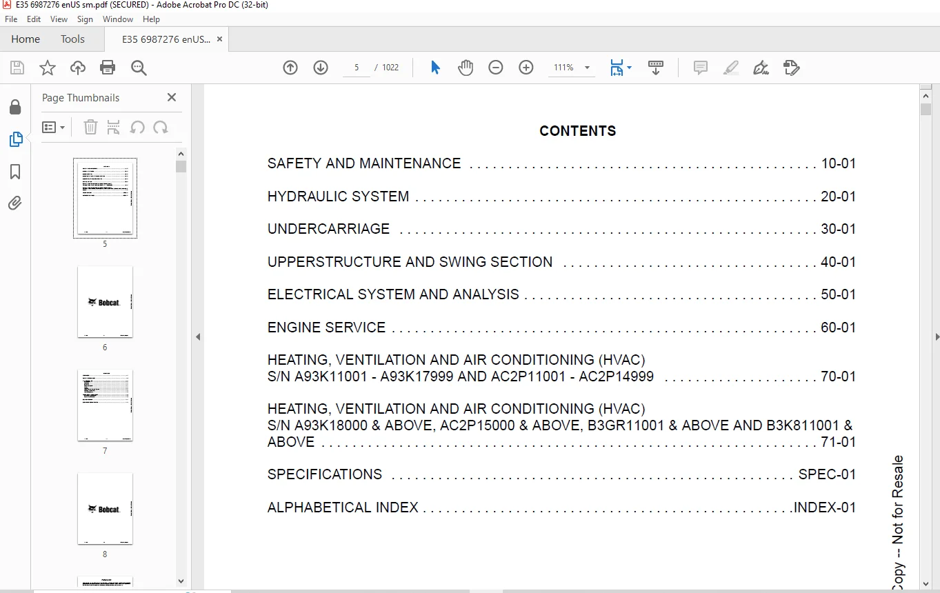
MAINTENANCE SAFETY 3
CONTENTS 5
FOREWORD 7
FOREWORD 9
SAFETY INSTRUCTIONS 11
FIRE PREVENTION 13
Maintenance 13
Operation 13
Electrical 13
Hydraulic System 13
Fueling 13
Starting 13
Spark Arrester Exhaust System 13
Welding And Grinding 14
Fire Extinguishers 14
SERIAL NUMBER LOCATIONS 15
Excavator Serial Number 15
Engine Serial Number 15
DELIVERY REPORT 16
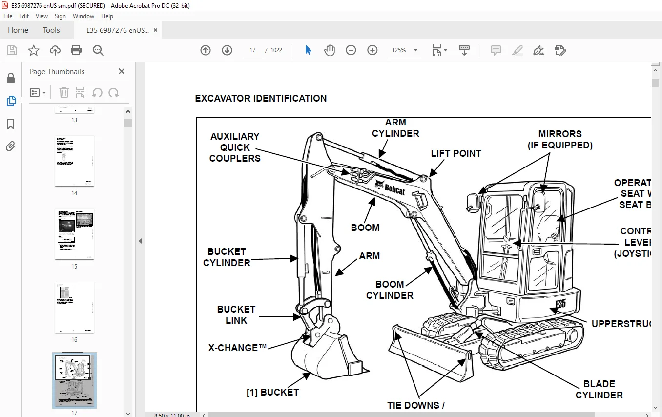
EXCAVATOR IDENTIFICATION 17
SAFETY AND MAINTENANCE 19
LIFTING AND BLOCKING THE EXCAVATOR 23
Procedure 23
LIFTING THE EXCAVATOR 25
Procedure 25
OPERATOR CAB (ROPS / TOPS) 27
Description 27
Cab Door 27
Front Window 28
Front Wiper 29
Window Washer Reservoir 29
Right Side Window 30
OPERATOR CANOPY (ROPS / TOPS) 31
Description 31
TRANSPORTING THE EXCAVATOR ON A TRAILER 33
Loading And Unloading 33
Fastening 33
TAILGATE 35
Opening And Closing 35
Adjusting The Latch 35
RIGHT SIDE COVER 37
Opening And Closing 37
SERVICE SCHEDULE 39
Maintenance Intervals 39
AIR CLEANER SERVICE 41
Daily Check 41
Replacing The Filter Elements 41
CAB FILTERS (S/N A93K11001 – A93K17999 AND AC2P11001 – AC2P14999) 43
Cleaning And Maintenance 43
CAB FILTERS (S/N A93K18000 & ABOVE, AC2P15000 & ABOVE, B3GR11001 & ABOVE AND B3K811001 & ABOVE) 45
Cleaning And Maintenance 45
ENGINE COOLING SYSTEM 47
Cleaning 47
Checking Level 48
Removing And Replacing Coolant 49
FUEL SYSTEM 51
Fuel Specifications 51
Biodiesel Blend Fuel 51
Filling The Fuel Tank 52
Fuel Filters 52
Draining The Fuel Tank 53
Removing Air From The Fuel System 54
ENGINE LUBRICATION SYSTEM 55
Checking And Adding Engine Oil 55
Oil Chart 55
Removing And Replacing Oil And Filter 56
HYDRAULIC SYSTEM 57
Checking And Adding Hydraulic Fluid 57
Hydraulic / Hydrostatic Fluid Chart 58
Removing And Replacing Hydraulic Filters 58
Removing And Replacing Hydraulic Fluid 60
LUBRICATION OF THE HYDRAULIC EXCAVATOR 63
Lubrication Locations 63
PIVOT PINS 67
Inspection And Maintenance 67
TRAVEL MOTOR 69
Checking And Adding Oil 69
Removing And Replacing Oil 69
SPARK ARRESTER MUFFLER 71
Cleaning Procedure 71
EMERGENCY EXIT 73
Right Side Rear Window 73
Front Window 73
SEAT BELT 75
Inspection And Maintenance 75
CONTROL CONSOLE LOCKOUTS 77
Inspection And Maintenance 77
TOWING THE EXCAVATOR 79
Procedure 79
REMOTE START TOOL KIT – MEL1563 81
Remote Start Tool – MEL1563 81
Service Tool Harness Control – MEL1565 82
Service Tool Harness Communicator – MEL1566 83
REMOTE START TOOL (SERVICE TOOL) KIT – 7217666 85
Description 85
Remote Start Tool (Service Tool) – 7022042 86
Excavator Service Tool Harness – 6689747 87
Computer Service Tool Harness – 6689746 88
HYDRAULIC SYSTEM 89
HYDRAULIC / HYDROSTATIC SCHEMATICS 95
HYDRAULIC SYSTEM INFORMATION 103
Glossary Of Hydraulic / Hydrostatic Symbols 103
Troubleshooting The Hydraulic Circuit 106
Troubleshooting The Cylinder Circuit 107
Troubleshooting The Swing (Upperstructure Slew) Circuit 108
Troubleshooting The Travel Circuit 109
CYLINDER (BOOM) (S/N A93K13096 & ABOVE, AC2P13032 & ABOVE, B3GR11001 & ABOVE, AND B3K811001 & ABOVE) 111
Testing 111
Removal And Installation 113
Parts Identification 116
Disassembly 117
Assembly 120
CYLINDER (BOOM) (S/N A93K13095 & BELOW, AC2P13031 & BELOW) 125
Testing 125
Removal And Installation 127
Parts Identification 130
Disassembly 131
Assembly 134
CYLINDER (ARM) 139
Testing 139
Removal And Installation 141
Parts Identification 143
Disassembly 144
Assembly 146
CYLINDER (BOOM SWING) 151
Testing 151
Removal And Installation 153
Parts Identification 156
Disassembly 157
Assembly 159
CYLINDER (BUCKET) 163
Testing 163
Removal And Installation 165
Parts Identification 167
Disassembly 168
Assembly 170
CYLINDER (BLADE) 173
Testing 173
Removal And Installation 175
Parts Identification 176
Disassembly 177
Assembly 179
CYLINDER (CLAMP) 183
Testing 183
Removal And Installation 184
Parts Identification 186
Disassembly 187
Assembly 190
CYLINDER (ANGLE BLADE) 195
Testing 195
Removal And Installation 196
Parts Identification 198
Disassembly 199
Assembly 201
CYLINDER (EXTENDABLE ARM) 205
Testing 205
Parts Identification 207
Disassembly 208
Assembly 211
VALVE (MAIN RELIEF) 215
Description 215
VALVE (PORT RELIEF) 217
Testing And Adjusting 217
VALVE (CROSS PORT RELIEF) 219
Testing 219
Removal And Installation 221
Disassembly And Assembly 222
VALVE (PILOT PRESSURE RELIEF) 223
Testing And Adjusting 223
HYDRAULIC CONTROL VALVE 225
Description 225
Removal And Installation 225
Parts Identification 229
Disassembly 230
Assembly 236
Inlet Valve Section Disassembly And Assembly 240
Boom Swing Valve Section Disassembly And Assembly 242
Slew Valve Section Disassembly And Assembly 245
Blade Valve Section Disassembly And Assembly 246
Right And Left Travel Valve Section Disassembly And Assembly 249
Boom Valve Section Disassembly And Assembly 251
Auxiliary, Arm, Bucket And Angle Blade Valve Section Disassembly And Assembly 255
Outlet Valve Section Disassembly And Assembly 257
HYDRAULIC PUMP 259
Hydraulic Pump Work Sheet 259
Pump Testing 261
Description 269
Removal And Installation 269
Coupler Removal And Installation 270
Hydraulic Pump Startup 271
Gear Pump Disassembly And Assembly 272
Piston Pump Parts Identification 274
Piston Pump Disassembly And Assembly 275
MANIFOLD ASSEMBLY / ACCUMULATOR (WITHOUT ANGLE BLADE) 287
Description 287
Removal And Installation 287
Parts Identification 289
Disassembly And Assembly 290
MANIFOLD ASSEMBLY / ACCUMULATOR (WITH ANGLE BLADE) 297
Description 297
Removal And Installation 297
Parts Identification 299
Disassembly And Assembly 300
TRAVEL MOTOR 307
Removal And Installation 307
Parts Identification Hydraulic Motor 308
Parts Identification Gear Reduction Hub 309
Disassembly 310
Assembly 324
SWIVEL JOINT 341
Removal And Installation 341
Parts Identification 343
Disassembly And Assembly 344
SWING MOTOR 347
Removal And Installation 347
Parts Identification 348
Disassembly And Assembly 349
SWING MOTOR (DRIVE CARRIER) 357
Removal And Installation 357
Parts Identification 358
Disassembly And Assembly 359
CONTROL PATTERN SELECTOR VALVE 365
Removal And Installation 365
Parts Identification 366
Disassembly And Assembly 367
RIGHT CONTROL LEVER (JOYSTICK) (S/N A93K11001 – A93K17999 AND AC2P11001 – AC2P14999) 369
Testing 369
Handle Removal And Installation 370
Joystick Assembly Removal And Installation 372
Parts Identification 373
Disassembly 374
Assembly 379
RIGHT CONTROL LEVER (JOYSTICK) (S/N A93K18001 & ABOVE, AC2P15001 & ABOVE, B3GR11001 & ABOVE AND B3K811001 & ABOVE) 385
Testing 385
Handle Removal And Installation 386
Joystick Assembly Removal And Installation 388
Parts Identification 389
Disassembly 390
Assembly 394
LEFT CONTROL LEVER (JOYSTICK) (S/N A93K11001 – A93K17999 AND AC2P11001 – AC2P14999) 399
Testing 399
Handle Removal And Installation 400
Joystick Assembly Removal And Installation 402
Parts Identification 403
Disassembly 404
Assembly 409
LEFT CONTROL LEVER (JOYSTICK) (S/N A93K18001 & ABOVE, A2CP15001 & ABOVE, B3GR11001 & ABOVE AND B3K811001 & ABOVE) 415
Testing 415
Handle Removal And Installation 416
Joystick Assembly Removal And Installation 418
Parts Identification 419
Disassembly 420
Assembly 424
HYDRAULIC FILTER MOUNT 429
Removal And Installation 429
HYDRAULIC RESERVOIR 431
Removal And Installation 431
OIL COOLER 433
Removal And Installation 433
DIRECT TO TANK VALVE 435
Removal And Installation 435
BLADE CONTROL LEVER 437
Handle Removal And Installation 437
Removal And Installation 439
Parts Identification 441
Disassembly And Assembly 442
CASE DRAIN FILTER MOUNT 447
Removal And Installation 447
TRAVEL CONTROL VALVE 449
Removal And Installation 449
Parts Identification 450
Disassembly And Assembly 451
REMOVING AIR FROM THE HYDRAULIC SYSTEM 457
Procedure 457
HYDRAULIC X-CHANGE MANIFOLD (EARLY MODELS) 459
Removal And Installation 459
Parts Identification 460
Disassembly And Assembly 461
HYDRAULIC X-CHANGE MANIFOLD (LATER MODELS) 465
Removal And Installation 465
Parts Identification 466
Disassembly And Assembly 467
SECONDARY AUXILIARY VALVE (EARLY MODELS) 473
Removal And Installation 473
Parts Identification 475
Disassembly And Assembly 476
SECONDARY AUXILIARY VALVE (LATER MODELS) 481
Removal And Installation 481
Parts Identification 483
VALVE (BOOM LOCK) 487
Removal And Installation 487
VALVE (ARM LOCK) 489
Removal And Installation 489
UNDERCARRIAGE 491
BLADE 493
Removal And Installation 493
ANGLE BLADE 495
Removal And Installation 495
TRACK UNDERCARRIAGE COMPONENTS (RUBBER TRACK) 497
Description 497
Track Lug Height 497
Checking Tension 498
Adjusting Tension 499
Track Removal And Installation 501
Idler Removal And Installation 502
Parts Identification 503
Idler Disassembly 504
Idler Assembly 506
Track Tensioner Removal And Installation 509
Track Tensioner Parts Identification 510
Track Tensioner Disassembly And Assembly 511
Roller Removal And Installation 513
Sprocket Removal And Installation 514
TRACK UNDERCARRIAGE COMPONENTS (STEEL TRACK) 515
Description 515
Checking Tension 516
Adjusting Tension 517
Track Removal And Installation 519
Idler Removal And Installation 522
Idler Parts Identification 523
Idler Disassembly 524
Idler Assembly 526
Track Tensioner Disassembly And Assembly 529
Track Tensioner Cylinder Parts Identification 530
Track Tensioner Disassembly And Assembly 531
Roller Removal And Installation 533
Sprocket Removal And Installation 534
Guide Plate Removal And Installation 534
TRACK MAINTENANCE 535
Track Damage Identification 535
SWING CIRCLE GEAR 547
Swing Bearing Removal 547
Swing Bearing Installation 548
UPPERSTRUCTURE AND SWING SECTION 549
UPPERSTRUCTURE 553
Removal 553
Installation 555
ROPS CANOPY 557
Removal And Installation 557
CAB 561
Removal And Installation 561
Door Removal And Installation 564
Front Window Removal And Installation 565
Right Side Rear Sliding Window Removal And Installation 566
Right Side Front Sliding Window Removal And Installation 566
Right Side Front And Rear Sliding Window Weather Strip Removal And Installation 567
Right Side Front And Rear Sliding Window Wiper Strip Removal And Installation 567
Glass Removal 568
Glass Installation 569
SEAT 575
Removal And Installation 575
Seat Mount Removal And Installation 576
RIGHT CONSOLE (S/N A93K11001 – A93K17999 AND AC2P11001 – AC2P14999) 577
Console Cover Removal And Installation 577
RIGHT CONSOLE (S/N A93K18000 & ABOVE, AC2P15000 & ABOVE, B3GR11001 & ABOVE AND B3K811001 & ABOVE) 583
Console Cover Removal And Installation 583
LEFT CONSOLE 589
Lower Console Cover Removal And Installation 589
Upper Console Cover Removal And Installation 590
Compression Spring Removal And Installation 593
Lock Lever Removal And Installation 595
Console Removal And Installation 595
LEFT UPPERSTRUCTURE COVER 597
Removal And Installation 597
RIGHT UPPERSTRUCTURE COVER 599
Removal And Installation 599
COUNTERWEIGHT 601
Removal And Installation 601
Long Arm Counterweight Removal And Installation 604
TRAVEL LEVERS AND PEDALS 605
Removal And Installation 605
Disassembly And Assembly 606
FLOOR MAT 607
Removal And Installation 607
FUEL TANK 609
Removal And Installation (Canopy Equipped Excavator) 609
Removal And Installation (Cab Equipped Excavator) 610
HORN 613
Removal And Installation 613
SWING FRAME 615
Removal And Installation 615
Boom Swing Frame Hose Routing 619
Bushing Removal 620
Bushing Installation 621
BOOM 623
Removal And Installation 623
ARM (STANDARD AND LONG) 625
Removal And Installation 625
Arm To Boom Bushing Removal And Installation 626
Arm To Bucket And Bucket Link Bushing Removal And Installation 627
ARM (EXTENDABLE) 629
Removal And Installation 629
Arm To Boom Bushing Removal And Installation 630
Arm To Bucket Bushing Removal And Installation 631
Disassembly And Assembly 632
Shimming Procedure 640
BUCKET 641
Bucket Teeth Removal And Installation 641
Bucket Side Cutting Edge Removal And Installation 642
CLAMP 643
Removal And Installation 643
TAILGATE 645
Removal And Installation 645
Latch Removal And Installation 646
X-CHANGE 647
Removal And Installation 647
Disassembly 649
Assembly 650
X-CHANGE (HYDRAULIC) 653
Removal And Installation 653
Parts Identification 655
Disassembly 656
Assembly 661
QUICK COUPLER (KLAC™ SYSTEM) 669
Troubleshooting 669
Daily Inspection 669
Removal And Installation 670
Parts Identification 672
Disassembly 673
Assembly 674
QUICK COUPLER (LEHNHOFF® SYSTEM) 677
Troubleshooting 677
Daily Inspection 677
Removal (MS03 And MS08) 678
Installation (MS03 And MS08) 679
Parts Identification (MS03) 680
Disassembly And Assembly (MS03) 681
Parts Identification (MS08) 682
Disassembly (MS08) 683
Assembly (MS08) 686
QUICK COUPLER (PIN GRABBER) 691
Troubleshooting 691
Daily Inspection 692
Removal And Installation 692
Parts Identification 694
Disassembly And Assembly 695
RIGHT SIDE COVER 699
Removal And Installation 699
Latch Removal And Installation 700
Latch Adjustment 701
TOOL BOX 703
Removal And Installation 703
ELECTRICAL SYSTEM AND ANALYSIS 705
ELECTRICAL SCHEMATICS 707
ELECTRICAL SYSTEM INFORMATION 715
Troubleshooting Chart 715
Description 716
Fuse And Relay Location / Identification 716
BATTERY 719
Servicing 719
Removal And Installation 720
Using A Booster Battery (Jump Starting) 721
ALTERNATOR 723
Belt Adjustment 723
Belt Replacement 723
Charging System Inspection 724
Alternator Voltage Testing 725
Low Voltage Testing 725
High Voltage Testing 726
Removal And Installation 726
Parts Identification 728
STARTER 729
Testing 729
Removal And Installation 730
Parts Identification 731
LIGHTS 733
Removal And Installation 733
Boom Light Removal And Installation 734
Boom Light Bulb Replacement 734
MAGNETIC LOCKOUT SENSOR 735
Removal And Installation 735
FUEL LEVEL SENDER 737
Removal And Installation 737
Testing 738
DIAGNOSTICS SERVICE CODES (S/N A93K11001 – A93K17999 AND AC2P11001 – AC2P14999) 739
Service Codes List 739
DIAGNOSTIC SERVICE CODES (S/N A93K1800 & ABOVE, AC2P1500 & ABOVE, B3GR11001 & ABOVE, B3K811001 & ABOVE) 741
Viewing Service Codes 741
Service Codes List 742
DELUXE INSTRUMENT PANEL SETUP (S/N A93K11001 – A93K17999 AND AC2P11001 – AC2P14999) 745
Passwords 745
Password Entry (For Starting And Operating The Machine) 745
Changing The Operator Password 745
Password Lockout Feature 746
Job Clock 746
RPM 746
CONTROL PANEL SETUP (S/N A93K18000 & ABOVE, AC2P15000 & ABOVE, B3GR11001 & ABOVE AND B3K811001 & ABOVE) 747
Panel Setup (Deluxe Instrument Panel) 747
Password Setup (Keyless Start Panel) 754
Password Setup (Deluxe Instrument Panel) 756
Maintenance Clock 758
INSTRUMENT PANEL / CONTROLLER (S/N A93K11001 – A93K17999 AND AC2P11001 – AC2P14999) 761
Removal And Installation 761
INSTRUMENT PANEL (S/N A93K18000 & ABOVE, AC2P15000 & ABOVE, B3GR11001 & ABOVE AND B3K811001 & ABOVE) 763
Removal And Installation 763
CONTROLLER (S/N A93K18000 & ABOVE, AC2P15000 & ABOVE, B3GR11001 & ABOVE AND B3K811001 & ABOVE) (GATEWAY AND AUXILIARY) 765
Description 765
Gateway Controller Removal And Installation 765
Auxiliary Controller Removal And Installation 766
KEY SWITCH 767
Removal And Installation 767
WIPER MOTOR 769
Removal And Installation 769
MOTION ALARM SYSTEM 771
Description 771
Inspecting 771
Adjusting Switch Position 772
SERVICE PC (LAPTOP COMPUTER) 773
Connecting The Remote Start Tool 773
Connecting Remote Start Tool (Service Tool) 773
Operation 774
SHUT-OFF SWITCH 775
Description 775
Removal And Installation 776
ENGINE SERVICE 779
ENGINE INFORMATION 781
Description 781
Specifications 782
Crankshaft Re-Grind Data 788
Torque For Kubota® Metric Bolts 789
Troubleshooting 790
Engine Removal And Installation 791
Compression – Checking 797
ENGINE SPEED CONTROL 799
Removal And Installation 799
Auto Idle Description 799
Auto Idle Controller Removal And Installation 800
Calibration 801
Actuator Removal And Installation 804
MUFFLER 807
Removal And Installation 807
AIR CLEANER 809
Housing Removal And Installation 809
ENGINE COOLING SYSTEM 811
Radiator Removal And Installation 811
Fan Removal And Installation 814
Water Pump Removal And Installation 815
Water Pump Disassembly And Assembly 815
Thermostat Housing Removal And Installation 816
Thermostat – Testing 816
LUBRICATION SYSTEM 817
Oil Pan Removal And Installation 817
Oil Pump Removal And Installation 817
Oil Pump Inspection 818
Engine Oil Pressure – Testing 819
FUEL SYSTEM 821
Fuel Shutoff Solenoid – Checking 821
Fuel Shut-off Solenoid Removal And Installation 822
Fuel Injection Pump – Checking 823
Fuel Injection Pump Removal And Installation 824
Fuel Injection Pump – Timing 827
Fuel Camshaft Removal And Installation 829
Fuel Camshaft Governor 830
Fuel Injector Removal And Installation 831
Fuel Injector Nozzle Pressure – Checking 833
Nozzle Spray Condition 834
Valve Seat Tightness 834
CYLINDER HEAD 835
Glow Plugs – Testing 835
Glow Plugs Removal And Installation 836
Valve Clearance Adjustment 837
Valve Timing – Checking 837
Cylinder Head Removal And Installation 838
Cylinder Head Disassembly And Assembly 841
Cylinder Head – Servicing 842
Cylinder Head Top Clearance 842
Valve Guide – Checking 843
Valve Guide Removal And Installation 844
Reconditioning The Valve And Valve Seat 845
Valve Spring 846
Valve Tappets 847
Rocker Arm And Shaft – Checking 848
Push Rod Alignment – Checking 848
CRANKSHAFT AND PISTONS 849
Piston And Connecting Rod Removal And Installation 849
Piston And Connecting Rod – Servicing 851
Cylinder Bore – Checking 853
Connecting Rod Alignment 853
Crankshaft Gear Removal And Installation 854
Crankshaft And Bearings Removal And Installation 855
Crankshaft And Bearings – Servicing 857
CAMSHAFT AND TIMING GEARS 861
Timing Gearcase Cover Removal And Installation 861
Timing Gears Backlash – Checking 863
Idle Gear And Camshaft Removal And Installation 864
Camshaft – Servicing 866
Idle Gear And Shaft – Servicing 867
FLYWHEEL AND HOUSING 869
Hydraulic Pump Coupler Removal And Installation 869
Flywheel Removal And Installation 871
Flywheel Ring Gear 871
HEATING, VENTILATION AND AIR CONDITIONING (HVAC) S/N A93K11001 – A93K17999 AND AC2P11001 – AC2P14999 873
AIR CONDITIONING SYSTEM FLOW 875
Description 875
Chart 876
Components 877
Safety Equipment 880
REGULAR MAINTENANCE 881
Cab Filters 881
Fan Belt Adjustment 882
Fan Belt Replacement 882
Condenser 884
Air Conditioning Lubrication 884
Evaporator / Heater Coil 884
Air Conditioning Service Chart 885
TROUBLESHOOTING 887
Blower Motor Does Not Operate 887
Blower Motor Operates Normally, But Air Flow Is Insufficient 887
Insufficient Cooling Although Air Flow And Compressor Operation Are Normal 887
The Compressor Operates Improperly Or Not At All 887
Gauge Pressure Related Troubleshooting 888
Temperature / Pressure Chart 889
Poor A/C Performance 890
HVAC Repair And Leaks 890
Electrical System 891
Engine Coolant Bypassing The Heater Valve 893
SYSTEM CHARGING AND RECLAMATION 895
Refrigerant Identification 895
Reclamation And Charging With Recovery / Charging Unit 897
COMPRESSOR 899
Removal And Installation 899
Oil 902
Oil Check 903
CONDENSER 905
Removal And Installation 905
RECEIVER / DRIER 907
Receiver / Drier Removal And Installation 907
Pressure Relief Valve Removal And Installation 908
Pressure Switch Removal And Installation 908
EVAPORATOR / HEATER UNIT 909
Removal And Installation 909
THERMOSTAT 911
Description 911
Removal And Installation 912
EXPANSION VALVE 915
Removal And Installation 915
EVAPORATOR COIL 917
Removal And Installation 917
HEATER COIL 919
Removal And Installation 919
BLOWER FAN 921
Removal And Installation 921
HEATER VALVE 923
Removal And Installation 923
HVAC DUCT 925
Removal And Installation 925
HEATING, VENTILATION AND AIR CONDITIONING (HVAC) S/N A93K18000 & ABOVE, AC2P15000 & ABOVE, B3GR11001 & ABOVE AND B3K811001 & ABOVE 927
AIR CONDITIONING SYSTEM FLOW 929
Description 929
Chart 930
Components 931
Safety Equipment 934
REGULAR MAINTENANCE 935
Cab Filters 935
Air Conditioning Compressor Belt Adjustment 936
Air Conditioning Compressor Belt Replacement 936
Condenser 937
Air Conditioning Lubrication 937
Evaporator / Heater Coil 937
Air Conditioning Service Chart 939
TROUBLESHOOTING 941
Blower Motor Does Not Operate 941
Blower Motor Operates Normally, But Air Flow Is Insufficient 941
Insufficient Cooling Although Air Flow And Compressor Operation Are Normal 941
The Compressor Operates Improperly Or Not At All 941
Gauge Pressure Related Troubleshooting 942
Temperature / Pressure Chart 943
Poor A/C Performance 944
HVAC Repair And Leaks 944
Electrical System 945
Engine Coolant Bypassing The Heater Valve 947
SYSTEM CHARGING AND RECLAMATION 949
Refrigerant Identification 949
Reclamation And Charging With Recovery / Charging Unit 951
COMPRESSOR 953
Removal And Installation 953
Oil 955
Oil Check 956
CONDENSER 959
Removal And Installation 959
RECEIVER / DRIER 961
Receiver / Drier Removal And Installation 961
Pressure Relief Valve Removal And Installation 962
Pressure Switch Removal And Installation 962
EVAPORATOR / HEATER UNIT 963
Removal And Installation 963
THERMOSTAT 965
Description 965
Removal And Installation 966
EXPANSION VALVE 969
Removal And Installation 969
EVAPORATOR COIL 971
Removal And Installation 971
HEATER COIL 973
Removal And Installation 973
BLOWER FAN 975
Removal And Installation 975
HEATER VALVE 977
Removal And Installation 977
HVAC DUCT 979
Removal And Installation 979
SPECIFICATIONS 981
EXCAVATOR SPECIFICATIONS 983
Excavator Machine Dimensions 983
Excavator Machine Dimensions – Standard Arm 984
Excavator Machine Dimensions – Long Arm 985
Excavator Machine Dimensions – Extendable Arm 986
Excavator Machine Dimensions – Angle Blade 987
Performance 988
Controls 988
Engine 989
Hydraulic System 989
Hydraulic Cylinders 990
Hydraulic Cycle Times 990
Drive System 990
Slew System 990
Undercarriage 990
Electrical 991
Capacities 991
Tracks 991
Ground Pressure 992
TECHNICAL SERVICE GUIDE SPECIFICATIONS 993
Engine 993
Engine Torques 993
Cooling System 993
Excavator Torques 993
TORQUE SPECIFICATION FOR BOLTS 995
Torque For General SAE Bolts 995
Torque For General Metric Bolts 996
HYDRAULIC CONNECTION SPECIFICATIONS 997
O-ring Face Seal Connection 997
Straight Thread O-ring Fitting 997
Tubelines And Hoses 998
Flare Fitting 998
O-ring Flare Fitting 999
Port Seal Fitting 1001
Push To Connect Fittings 1002
HYDRAULIC FLUID SPECIFICATIONS 1005
Specifications 1005
CONVERSIONS 1007
Decimal And Millimeter Equivalent Chart 1007
U S To Metric Conversion Chart 1008
SERVICE TOOLS REQUIRED 1009
Remote Start Tools 1009
Hydraulic Tools 1010
Engine Tools 1013
Electrical Tools 1015
HVAC Tools 1015
ALPHABETICAL INDEX 1017
Customer Support: [email protected]
https://vimeo.com/841752256?share=copy
PLEASE NOTE:
- This is the SAME exact manual used by your dealers to fix your vehicle.
- The same can be yours in the next 2-3 mins as you will be directed to the download page immediately after paying for the manual.
- Any queries / doubts regarding your purchase, please feel free to contact [email protected]
s.m