Bobcat E35i Compact Excavator Service Manual SN AUYM11001 & Above – PDF DOWNLOAD
$34.95
Bobcat E35i Compact Excavator Service Manual SN AUYM11001 & Above – PDF DOWNLOAD
S/N AUYM11001 & Above
Description
Bobcat E35i Compact Excavator Service Manual SN AUYM11001 & Above – PDF DOWNLOAD
FILE DETAILS:
Bobcat E35i Compact Excavator Service Manual SN AUYM11001 & Above – PDF DOWNLOAD
Language : English
Pages :917
Downloadable : Yes
File Type : PDF
DESCRIPTION:
Bobcat E35i Compact Excavator Service Manual SN AUYM11001 & Above – PDF DOWNLOAD
S/N AUYM11001 & Above
FOREWORD
This manual is for the Bobcat excavator mechanic. It provides necessary servicing and adjustment procedures for the Bobcat excavator and its component parts and systems. Refer to the Operation & Maintenance Manual for operating instructions, starting procedure, daily checks, etc.
SAFETY INSTRUCTIONS
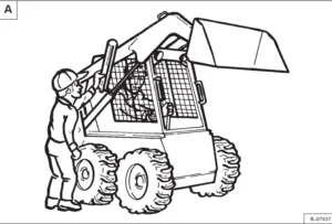
Instructions are necessary before operating or servicing machine. Read and understand the Operation & Maintenance Manual, Operator’s Handbook and signs (decals) on machine. Follow warnings and instructions in the manuals when making repairs, adjustments or servicing. Check for correct function after adjustments, repairs or service. Untrained operators and failure to follow instructions can cause injury or death.
The following publications provide information on the safe use and maintenance of the Bobcat machine and attachments:
- The Delivery Report is used to assure that complete instructions have been given to the new owner and that the machine is in safe operating condition.
- The Operation & Maintenance Manual delivered with the machine or attachment contains operating information as well as routine maintenance and service procedures. It is a part of the machine and can be stored in a container provided on the machine. Replacement Operation & Maintenance Manuals can be ordered from your Bobcat dealer.
- Machine signs (decals) instruct on the safe operation and care of your Bobcat machine or attachment. The signs and their locations are shown in the Operation & Maintenance Manual. Replacement signs are available from your Bobcat dealer.
- An Operator’s Handbook fastened to the operator cab. It’s brief instructions are convenient to the operator. The handbook is available from your dealer in an English edition or one of many other languages. See your Bobcat dealer for more information on translated versions.
- The AEM Safety Manual delivered with the machine gives general safety information.
- The Service Manual and Parts Manual are available from your dealer for use by mechanics to do shoptype service and repair work.
IMAGES PREVIEW OF THE MANUAL:
TABLE OF CONTENTS:
Bobcat E35i Compact Excavator Service Manual SN AUYM11001 & Above – PDF DOWNLOAD
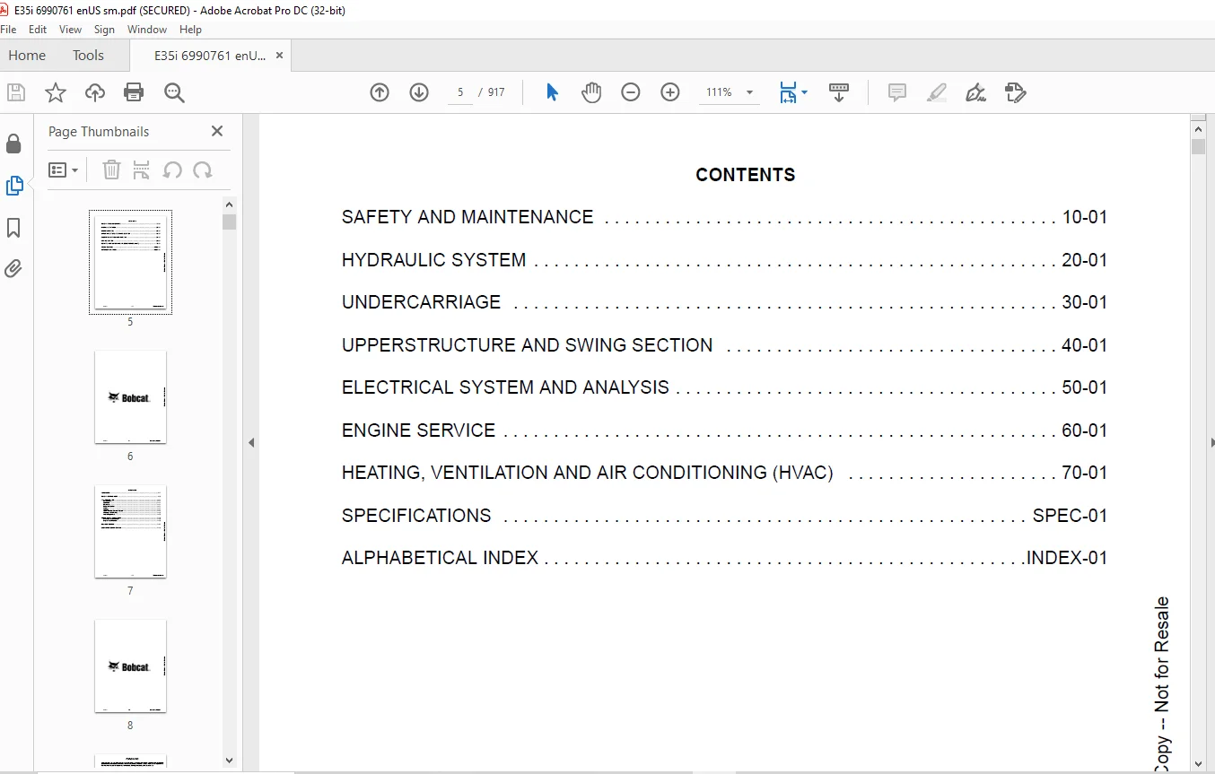
MAINTENANCE SAFETY 3
CONTENTS 5
FOREWORD 7
FOREWORD 9
SAFETY INSTRUCTIONS 11
FIRE PREVENTION 13
Maintenance 13
Operation 13
Electrical 13
Hydraulic System 13
Fueling 13
Starting 13
Spark Arrester Exhaust System 13
Welding And Grinding 14
Fire Extinguishers 14
SERIAL NUMBER LOCATIONS 15
Excavator Serial Number 15
Engine Serial Number 15
DELIVERY REPORT 16
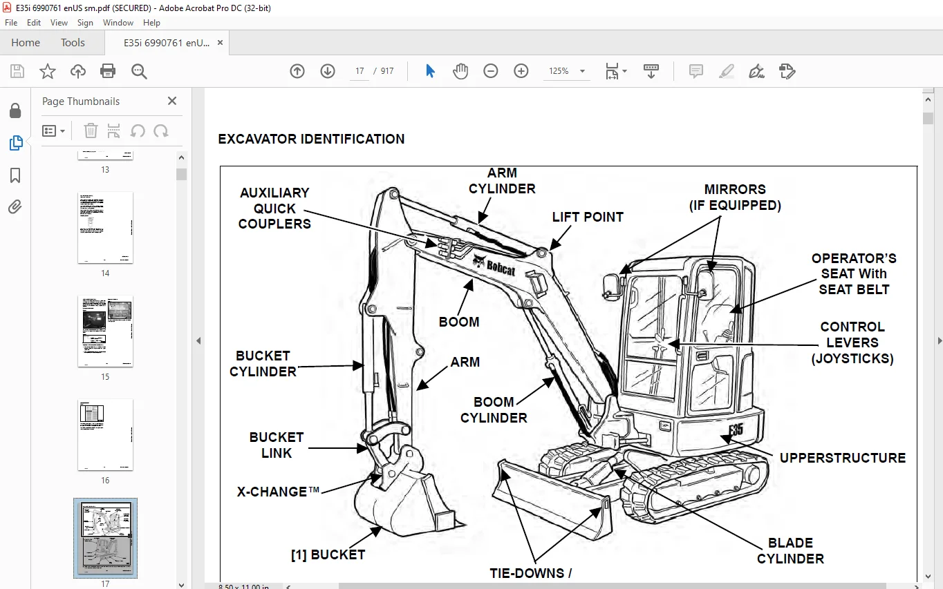
EXCAVATOR IDENTIFICATION 17
SAFETY AND MAINTENANCE 19
LIFTING AND BLOCKING THE EXCAVATOR 23
Procedure 23
LIFTING THE EXCAVATOR 25
Procedure 25
OPERATOR CAB (ROPS / TOPS) 27
Description 27
Cab Door 28
Front Window 29
Front Wiper 30
Window Washer Reservoir 30
Right Side Window 31
OPERATOR CANOPY (ROPS / TOPS) 33
Description 33
TRANSPORTING THE EXCAVATOR ON A TRAILER 35
Loading And Unloading 35
Fastening 35
TAILGATE 37
Opening And Closing 37
Adjusting The Latch 37
RIGHT SIDE COVER 39
Opening And Closing 39
SERVICE SCHEDULE 41
Maintenance Intervals 41
AIR CLEANER SERVICE 43
Daily Check 43
Replacing The Filter Elements 43
CAB FILTERS 45
Cleaning And Maintenance 45
ENGINE COOLING SYSTEM 47
Cleaning 47
Checking Level 48
Removing And Replacing Coolant 49
FUEL SYSTEM 51
Fuel Specifications 51
Biodiesel Blend Fuel 51
Filling The Fuel Tank 52
Fuel Filters 52
Draining The Fuel Tank 53
Removing Air From The Fuel System 54
ENGINE LUBRICATION SYSTEM 55
Checking And Adding Engine Oil 55
Engine Oil Chart 55
Removing And Replacing Oil And Filter 56
HYDRAULIC SYSTEM 57
Checking And Adding Hydraulic Fluid 57
Hydraulic / Hydrostatic Fluid Chart 58
Removing And Replacing Hydraulic Filters 58
Removing And Replacing Hydraulic Fluid 60
LUBRICATING THE EXCAVATOR 63
Lubrication Locations 63
PIVOT PINS 67
Inspection And Maintenance 67
TRAVEL MOTOR 69
Checking And Adding Oil 69
Removing And Replacing Oil 69
SPARK ARRESTER MUFFLER 71
Cleaning Procedure 71
EMERGENCY EXIT 73
Right Side Rear Window 73
Front Window 73
SEAT BELT 75
Inspection And Maintenance 75
CONTROL CONSOLE LOCKOUTS 77
Inspection And Maintenance 77
TOWING THE EXCAVATOR 79
Procedure 79
REMOTE START TOOL KIT – MEL1563 81
Remote Start Tool Kit – MEL1563 81
Service Tool Harness Control – MEL1565 82
Service Tool Harness Communicator – MEL1566 83
REMOTE START TOOL (SERVICE TOOL) KIT – 7217666 85
Description 85
Remote Start Tool (Service Tool) – 7022042 86
Excavator Service Tool Harness – 6689747 87
Computer Service Tool Harness – 6689746 88
HYDRAULIC SYSTEM 89
HYDRAULIC / HYDROSTATIC SCHEMATICS 95
HYDRAULIC SYSTEM INFORMATION 97
Glossary Of Hydraulic / Hydrostatic Symbols 97
Troubleshooting The Hydraulic Circuit 100
Troubleshooting The Cylinder Circuit 101
Troubleshooting The Swing (Upperstructure Slew) Circuit 102
Troubleshooting The Travel Circuit 103
CYLINDER (BOOM) 105
Testing 105
Removal And Installation 107
Parts Identification 110
Disassembly 111
Assembly 114
CYLINDER (ARM) 119
Testing 119
Removal And Installation 121
Parts Identification 123
Disassembly 124
Assembly 126
CYLINDER (BOOM SWING) 131
Testing 131
Removal And Installation 133
Parts Identification 136
Disassembly 137
Assembly 139
CYLINDER (BUCKET) 143
Testing 143
Removal And Installation 144
Parts Identification 146
Disassembly 147
Assembly 149
CYLINDER (BLADE) 153
Testing 153
Removal And Installation 155
Parts Identification 156
Disassembly 157
Assembly 159
CYLINDER (CLAMP) 163
Testing 163
Removal And Installation 164
Parts Identification 166
Disassembly 167
Assembly 170
CYLINDER (ANGLE BLADE) 175
Testing 175
Removal And Installation 176
Parts Identification 178
Disassembly 179
Assembly 181
CYLINDER (EXTENDABLE ARM) 185
Testing 185
Parts Identification 187
Disassembly 188
Assembly 191
VALVE (MAIN RELIEF) 195
Description 195
VALVE (PORT RELIEF) 197
Testing And Adjusting Port Relief Valve Pressure 197
VALVE (CROSS PORT RELIEF) 199
Testing 199
Removal And Installation 201
Cross Port Relief Valve Disassembly And Assembly 201
VALVE (PILOT PRESSURE RELIEF) 203
Testing And Adjusting The Pilot Pressure Relief Valve 203
HYDRAULIC CONTROL VALVE 205
Description 205
Removal And Installation 205
Parts Identification 210
Disassembly 211
Assembly 217
Inlet Valve Section Disassembly And Assembly 221
Boom Swing Valve Section Disassembly And Assembly 223
Slew Valve Section Disassembly And Assembly 226
Blade Valve Section Disassembly And Assembly 227
Right And Left Travel Valve Section Disassembly And Assembly 230
Boom Valve Section Disassembly And Assembly 232
Auxiliary, Arm, Bucket And Angle Blade Valve Section Disassembly And Assembly 236
Outlet Valve Section Disassembly And Assembly 238
HYDRAULIC PUMP 241
Hydraulic Pump Work Sheet 241
Pump Testing 243
Description 251
Removal And Installation 251
Coupler Removal And Installation 252
Hydraulic Pump Startup 253
Gear Pump Disassembly And Assembly 254
Piston Pump Parts Identification 256
Piston Pump Disassembly And Assembly 257
MANIFOLD ASSEMBLY / ACCUMULATOR (WITHOUT ANGLE BLADE) 269
Description 269
Removal And Installation 269
Parts Identification 271
Disassembly And Assembly 272
MANIFOLD ASSEMBLY / ACCUMULATOR (WITH ANGLE BLADE) 279
Description 279
Removal And Installation 279
Parts Identification 281
Disassembly And Assembly 282
TRAVEL MOTOR 289
Removal And Installation 289
Parts Identification Hydraulic Motor 290
Parts Identification Gear Reduction Hub 291
Disassembly 292
Assembly 306
SWIVEL JOINT 323
Removal And Installation 323
Parts Identification 325
Disassembly And Assembly 326
SWING MOTOR 329
Removal And Installation 329
Parts Identification 330
Disassembly And Assembly 331
SWING MOTOR (DRIVE CARRIER) 337
Removal And Installation 337
Parts Identification 338
Disassembly And Assembly 339
CONTROL PATTERN SELECTOR VALVE 345
Removal And Installation 345
Parts Identification 346
Disassembly And Assembly 347
RIGHT CONTROL LEVER (JOYSTICK) 349
Testing 349
Handle Removal And Installation 350
Joystick Assembly Removal And Installation 352
Parts Identification 353
Disassembly 354
Assembly 359
LEFT CONTROL LEVER (JOYSTICK) 365
Testing 365
Handle Removal And Installation 366
Joystick Assembly Removal And Installation 368
Parts Identification 369
Disassembly 370
Assembly 375
HYDRAULIC FILTER MOUNT 381
Removal And Installation 381
HYDRAULIC RESERVOIR 383
Removal And Installation 383
OIL COOLER 385
Removal And Installation 385
DIRECT TO TANK VALVE 387
Removal And Installation 387
BLADE CONTROL LEVER 389
Handle Removal And Installation 389
Removal And Installation 391
Parts Identification 393
Disassembly And Assembly 394
CASE DRAIN FILTER MOUNT 399
Removal And Installation 399
TRAVEL CONTROL VALVE 401
Removal And Installation 401
Parts Identification 402
Disassembly And Assembly 403
REMOVING AIR FROM THE HYDRAULIC SYSTEM 409
Procedure 409
HYDRAULIC X-CHANGE MANIFOLD (EARLIER MODELS) 411
Removal And Installation 411
Parts Identification 412
Disassembly And Assembly 413
HYDRAULIC X-CHANGE MANIFOLD (LATER MODELS) 417
Removal And Installation 417
Parts Identification 418
Disassembly And Assembly 419
SECONDARY AUXILIARY VALVE (EARLIER MODELS) 425
Removal And Installation 425
Parts Identification 427
Disassembly And Assembly 428
SECONDARY AUXILIARY VALVE (LATER MODELS) 433
Removal And Installation 433
Parts Identification 435
Disassembly And Assembly 436
VALVE (BOOM LOCK) 439
Removal And Installation 439
VALVE (ARM LOCK) 441
Removal And Installation 441
UNDERCARRIAGE 443
BLADE 445
Removal And Installation 445
BLADE (ANGLE) 447
Removal And Installation 447
TRACK UNDERCARRIAGE COMPONENTS (RUBBER TRACK) 449
Description 449
Track Lug Height 449
Checking Tension 450
Adjusting Tension 451
Track Removal And Installation 453
Idler Removal And Installation 455
Parts Identification 456
Idler Disassembly 457
Idler Assembly 459
Track Tensioner Removal And Installation 462
Track Tensioner Parts Identification 463
Track Tensioner Disassembly And Assembly 464
Roller Removal And Installation 466
Sprocket Removal And Installation 467
TRACK UNDERCARRIAGE COMPONENTS (STEEL TRACK) 469
Description 469
Checking Tension 470
Adjusting Tension 471
Track Removal And Installation 473
Idler Removal And Installation 476
Idler Parts Identification 477
Idler Disassembly 478
Idler Assembly 480
Track Tensioner Disassembly And Assembly 483
Track Tensioner Parts Identification 484
Track Tensioner Disassembly And Assembly 485
Roller Removal And Installation 487
Sprocket Removal And Installation 488
Guide Plate Removal And Installation 488
TRACK MAINTENANCE 489
Track Damage Identification 489
SWING CIRCLE GEAR 501
Swing Bearing Removal 501
Swing Bearing Installation 502
UPPERSTRUCTURE AND SWING SECTION 503
UPPERSTRUCTURE 507
Removal 507
Installation 509
ROPS CANOPY 511
Removal And Installation 511
CAB 515
Removal And Installation 515
Door Removal And Installation 518
Front Window Removal And Installation 519
Front Window Disassembly And Assembly 520
Front Window Adjustment 521
Right Side Rear Sliding Window Removal And Installation 523
Right Side Front Sliding Window Removal And Installation 523
Right Side Front And Rear Sliding Window Weather Strip Removal And Installation 524
Right Side Front And Rear Sliding Window Wiper Strip Removal And Installation 524
Glass Removal 525
Glass Installation 526
SEAT 531
Removal And Installation 531
Seat Mount Removal And Installation 532
RIGHT CONSOLE 533
Console Cover Removal And Installation 533
LEFT CONSOLE 539
Lower Console Cover Removal And Installation 539
Upper Console Cover Removal And Installation 540
Compression Spring Removal And Installation 543
Lock Lever Removal And Installation 545
Console Removal And Installation 545
LEFT UPPERSTRUCTURE COVER 547
Removal And Installation 547
RIGHT UPPERSTRUCTURE COVER 549
Removal And Installation 549
COUNTERWEIGHT 551
Removal And Installation 551
Long Arm Counterweight Removal And Installation 554
TRAVEL LEVERS AND PEDALS 555
Removal And Installation 555
Disassembly And Assembly 556
FLOOR MAT 557
Removal And Installation 557
FUEL TANK 559
Removal And Installation (Canopy Equipped Excavator) 559
Removal And Installation (Cab Equipped Excavator) 560
Fuel Tank Fitting Removal And Installation 562
HORN 563
Removal And Installation 563
SWING FRAME 565
Removal And Installation 565
Boom Swing Frame Hose Routing 568
Bushing Removal 569
Bushing Installation 570
BOOM 571
Removal And Installation 571
ARM (STANDARD AND LONG) 573
Removal And Installation 573
Arm To Boom Bushing Removal And Installation 574
Arm To Bucket And Bucket Link Bushing Removal And Installation 575
ARM (EXTENDABLE) 577
Removal And Installation 577
Arm To Boom Bushing Removal And Installation 578
Arm To Bucket Bushing Removal And Installation 579
Disassembly And Assembly 580
Shimming Procedure 588
BUCKET 589
Bucket Teeth Removal And Installation 589
Bucket Side Cutting Edge Removal And Installation 590
CLAMP 591
Removal And Installation 591
TAILGATE 593
Removal And Installation 593
Latch Removal And Installation 594
X-CHANGE 595
Removal And Installation 595
Disassembly 596
Assembly 597
X-CHANGE (HYDRAULIC) 599
Removal And Installation 599
Parts Identification 601
Disassembly 602
Assembly 607
QUICK COUPLER (KLAC™ SYSTEM) 615
Troubleshooting 615
Daily Inspection 615
Removal And Installation 616
Parts Identification 618
Disassembly 619
Assembly 620
QUICK COUPLER (LEHNHOFF® SYSTEM) 623
Troubleshooting 623
Daily Inspection 623
Removal (MS03 And MS08) 624
Installation (MS03 And MS08) 625
Parts Identification (MS03) 626
Disassembly And Assembly (MS03) 627
Parts Identification (MS08) 628
Disassembly (MS08) 629
Assembly (MS08) 632
QUICK COUPLER (PIN GRABBER) 637
Troubleshooting 637
Daily Inspection 638
Removal And Installation 639
Parts Identification 640
Disassembly And Assembly 641
RIGHT SIDE COVER 645
Removal And Installation 645
Latch Removal And Installation 646
Latch Adjustment 647
TOOL BOX 649
Removal And Installation 649
ELECTRICAL SYSTEM AND ANALYSIS 651
ELECTRICAL SCHEMATICS 653
ELECTRICAL SYSTEM INFORMATION 660
Troubleshooting Chart 660
Description 661
Fuse And Relay Location / Identification 661
BATTERY 664
Servicing 664
Removal And Installation 665
Using A Booster Battery (Jump Starting) 666
ALTERNATOR 668
Belt Adjustment 668
Belt Replacement 668
Charging System Inspection 669
Alternator Voltage Testing 670
Low Voltage Testing 670
High Voltage Testing 671
Removal And Installation 672
Parts Identification 674
STARTER 676
Testing 676
Removal And Installation 677
Parts Identification 678
LIGHTS 680
Removal And Installation 680
Boom Light Removal And Installation 681
Boom Light Bulb Replacement 681
MAGNETIC LOCKOUT SENSOR 682
Removal And Installation 682
FUEL LEVEL SENDER 684
Removal And Installation 684
Testing 685
DIAGNOSTIC SERVICE CODES 686
Viewing Service Codes 686
Service Codes List 687
CONTROL PANEL SETUP 690
Panel Setup (Deluxe Instrument Panel) 690
Password Setup (Keyless Start Panel) 696
Password Setup (Deluxe Instrument Panel) 697
Maintenance Clock 699
INSTRUMENT PANEL 702
Removal And Installation 702
CONTROLLER 704
Description 704
Gateway Controller Removal and Installation 704
Auxiliary Controller Removal And Installation 706
KEY SWITCH 708
Removal And Installation 708
WIPER MOTOR 710
Removal And Installation 710
MOTION ALARM SYSTEM 712
Description 712
Inspecting 712
Adjusting Switch Position 713
SERVICE PC (LAPTOP COMPUTER) 714
Connecting The Remote Start Tool 714
Connecting Remote Start Tool (Service Tool) 714
SHUT-OFF SWITCH 716
Description 716
Removal And Installation 717
TRAVEL MOTOR AUTO-SHIFT 720
Auto-Shift Drive System (If Equipped) 720
Troubleshooting 721
ENGINE SERVICE 724
ENGINE INFORMATION 726
Description 726
Specifications 727
Crankshaft Re-Grind Data 733
Torque For Kubota Metric Bolts 734
Troubleshooting 735
Engine Removal And Installation 736
Compression – Testing 743
ENGINE SPEED CONTROL 744
Removal And Installation 744
Auto Idle Controller Removal And Installation 745
Calibration 746
Actuator Removal And Installation 749
MUFFLER 752
Removal And Installation 752
AIR CLEANER 754
Removal And Installation 754
ENGINE COOLING SYSTEM 756
Radiator Removal And Installation 756
Fan Removal And Installation 759
Water Pump Removal And Installation 760
Water Pump Disassembly And Assembly 761
Thermostat Housing Removal And Installation 762
Thermostat – Testing 763
LUBRICATION SYSTEM 764
Oil Pan Removal And Installation 764
Oil Pump Removal And Installation 765
Oil Pump Inspection 765
Engine Oil Pressure – Testing 766
FUEL SYSTEM 768
Fuel Shutoff Solenoid – Testing 768
Fuel Shut-off Solenoid Removal And Installation 769
Fuel Injection Pump – Testing 770
Fuel Injection Pump Removal And Installation 771
Fuel Injection Pump – Timing 774
Fuel Camshaft Removal And Installation 776
Fuel Camshaft Governor 777
Fuel Injector Removal And Installation 778
Fuel Injector Nozzle Pressure – Testing 781
Nozzle Spray Condition 782
Valve Seat Tightness 782
CYLINDER HEAD 784
Glow Plugs – Testing 784
Glow Plugs Removal And Installation 785
Valve Clearance Adjustment 786
Valve Timing – Inspecting 786
Cylinder Head Removal And Installation 787
Cylinder Head Disassembly And Assembly 790
Cylinder Head – Servicing 791
Cylinder Head Top Clearance 791
Valve Guide – Inspecting 792
Valve Guide Removal And Installation 793
Reconditioning The Valve And Valve Seat 794
Valve Spring 795
Valve Tappets 796
Rocker Arm And Shaft – Inspecting 797
Push Rod Alignment – Inspecting 797
CRANKSHAFT AND PISTONS 798
Piston And Connecting Rod Removal And Installation 798
Piston And Connecting Rod – Servicing 800
Cylinder Bore – Inspecting 802
Connecting Rod Alignment 803
Crankshaft Gear Removal And Installation 804
Crankshaft And Bearings Removal And Installation 805
Crankshaft And Bearings – Servicing 808
CAMSHAFT AND TIMING GEARS 812
Timing Gearcase Cover Removal And Installation 812
Timing Gears Backlash – Inspecting 815
Idle Gear And Camshaft Removal And Installation 816
Camshaft – Servicing 818
Idle Gear And Shaft – Servicing 819
FLYWHEEL AND HOUSING 820
Hydraulic Pump Coupler Removal And Installation 820
Flywheel Removal And Installation 822
Flywheel Ring Gear 822
HEATING, VENTILATION AND AIR CONDITIONING (HVAC) 824
AIR CONDITIONING SYSTEM FLOW 826
Description 826
Chart 827
Components 828
Safety Equipment 831
REGULAR MAINTENANCE 832
Cab Filters 832
Air Conditioning Compressor Belt Adjustment 833
Air Conditioning Compressor Belt Replacement 833
Condenser 834
Air Conditioning Lubrication 834
Evaporator / Heater Coil 835
Air Conditioning Service Chart 836
TROUBLESHOOTING 838
Blower Motor Does Not Operate 838
Blower Motor Operates Normally, But Air Flow Is Insufficient 838
Insufficient Cooling Although Air Flow And Compressor Operation Are Normal 838
The Compressor Operates Improperly Or Not At All 838
Gauge Pressure Related Troubleshooting 839
Temperature / Pressure Chart 840
Poor A/C Performance 841
HVAC Repair And Leaks 841
Electrical System 842
Engine Coolant Bypassing The Heater Valve 844
SYSTEM CHARGING AND RECLAMATION 846
Refrigerant Identification 846
Reclamation And Charging With Recovery / Charging Unit 848
COMPRESSOR 850
Removal And Installation 850
Oil 851
Oil Check 852
CONDENSER 854
Removal And Installation 854
RECEIVER / DRIER 856
Receiver / Drier Removal And Installation 856
Pressure Switch Removal And Installation 857
EVAPORATOR / HEATER UNIT 858
Removal And Installation 858
THERMOSTAT 860
Description 860
Removal And Installation 861
EXPANSION VALVE 864
Removal And Installation 864
EVAPORATOR COIL 866
Removal And Installation 866
HEATER COIL 868
Removal And Installation 868
BLOWER FAN 870
Removal And Installation 870
HEATER VALVE 872
Removal And Installation 872
HVAC DUCT 874
Removal And Installation 874
SPECIFICATIONS 876
E35i EXCAVATOR SPECIFICATIONS 878
Excavator Machine Dimensions 878
Excavator Machine Dimensions – Standard Arm 879
Excavator Machine Dimensions – Long Arm 880
Excavator Machine Dimensions – Extendable Arm 881
Excavator Machine Dimensions – Angle Blade 882
Performance 883
Controls 883
Engine 884
Hydraulic System 884
Hydraulic Cylinders 885
Hydraulic Cycle Times 885
Drive System 885
Slew System 885
Undercarriage 885
Electrical 886
Capacities 886
Tracks 887
Ground Pressure 887
TECHNICAL SERVICE GUIDE SPECIFICATIONS 888
Engine 888
Engine Torques 888
Cooling System 888
Excavator Torques 888
TORQUE SPECIFICATION FOR BOLTS 890
Torque For General SAE Bolts 890
Torque For General Metric Bolts 891
HYDRAULIC CONNECTION SPECIFICATIONS 892
O-ring Face Seal Connection 892
Straight Thread O-ring Fitting 892
Tubelines And Hoses 893
Flare Fitting 893
O-ring Flare Fitting 894
Port Seal Fitting 896
Push To Connect Fittings 897
HYDRAULIC FLUID SPECIFICATIONS 900
Specifications 900
CONVERSIONS 902
Decimal And Millimeter Equivalent Chart 902
U S To Metric Conversion Chart 903
SERVICE TOOLS REQUIRED 904
Remote Start Tools 904
Hydraulic Tools 905
Engine Tools 908
Electrical Tools 910
General Tools 910
HVAC Tools 911
ALPHABETICAL INDEX 912
Questions? Email us: [email protected]
https://vimeo.com/841770074?share=copy
PLEASE NOTE:
- This is the SAME exact manual used by your dealers to fix your vehicle.
- The same can be yours in the next 2-3 mins as you will be directed to the download page immediately after paying for the manual.
- Any queries / doubts regarding your purchase, please feel free to contact [email protected]
s.m