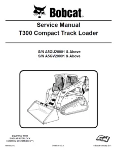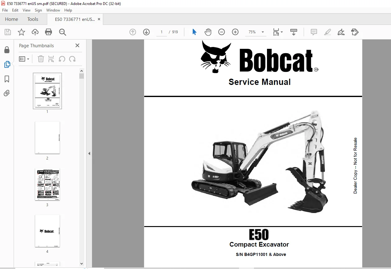
Bobcat E40 Compact Excavator Service Manual SN B4GP11001 & Above – PDF DOWNLOAD
$33.95
Bobcat E40 Compact Excavator Service Manual SN B4GP11001 & Above – PDF DOWNLOAD
S/N B4GP11001 & Above
Description
Bobcat E40 Compact Excavator Service Manual SN B4GP11001 & Above – PDF DOWNLOAD
FILE DETAILS:
Bobcat E40 Compact Excavator Service Manual SN B4GP11001 & Above – PDF DOWNLOAD
Language : English
Pages :919
Downloadable : Yes
File Type : PDF
DESCRIPTION:
S/N B4GP11001 & Above
Bobcat E40 Compact Excavator Service Manual SN B4GP11001 & Above – PDF DOWNLOAD
FOREWORD
This manual is for the Bobcat excavator mechanic. It provides necessary servicing and adjustment procedures for the Bobcat excavator and its component parts and systems. Refer to the Operation & Maintenance Manual for operating instructions, starting procedure, daily checks, etc.
SAFETY INSTRUCTIONS
Instructions are necessary before operating or servicing machine. Read and understand the Operation & Maintenance Manual, Operator’s Handbook and signs (decals) on machine. Follow warnings and instructions in the manuals when making repairs, adjustments or servicing. Check for correct function after adjustments, repairs or service. Untrained operators and failure to follow instructions can cause injury or death.
The following publications provide information on the safe use and maintenance of the Bobcat machine and attachments:
- The Delivery Report is used to assure that complete instructions have been given to the new owner and that the machine is in safe operating condition.
- The Operation & Maintenance Manual delivered with the machine or attachment contains operating information as well as routine maintenance and service procedures. It is a part of the machine and can be stored in a container provided on the machine. Replacement Operation & Maintenance Manuals can be ordered from your Bobcat dealer.
- Machine signs (decals) instruct on the safe operation and care of your Bobcat machine or attachment. The signs and their locations are shown in the Operation & Maintenance Manual. Replacement signs are available from your Bobcat dealer.
- An Operator’s Handbook fastened to the operator cab. It’s brief instructions are convenient to the operator. The handbook is available from your dealer in an English edition or one of many other languages. See your Bobcat dealer for more information on translated versions.
- The AEM Safety Manual delivered with the machine gives general safety information.
- The Service Manual and Parts Manual are available from your dealer for use by mechanics to do shoptype service and repair work.
IMAGES PREVIEW OF THE MANUAL:
TABLE OF CONTENTS:
Bobcat E40 Compact Excavator Service Manual SN B4GP11001 & Above – PDF DOWNLOAD
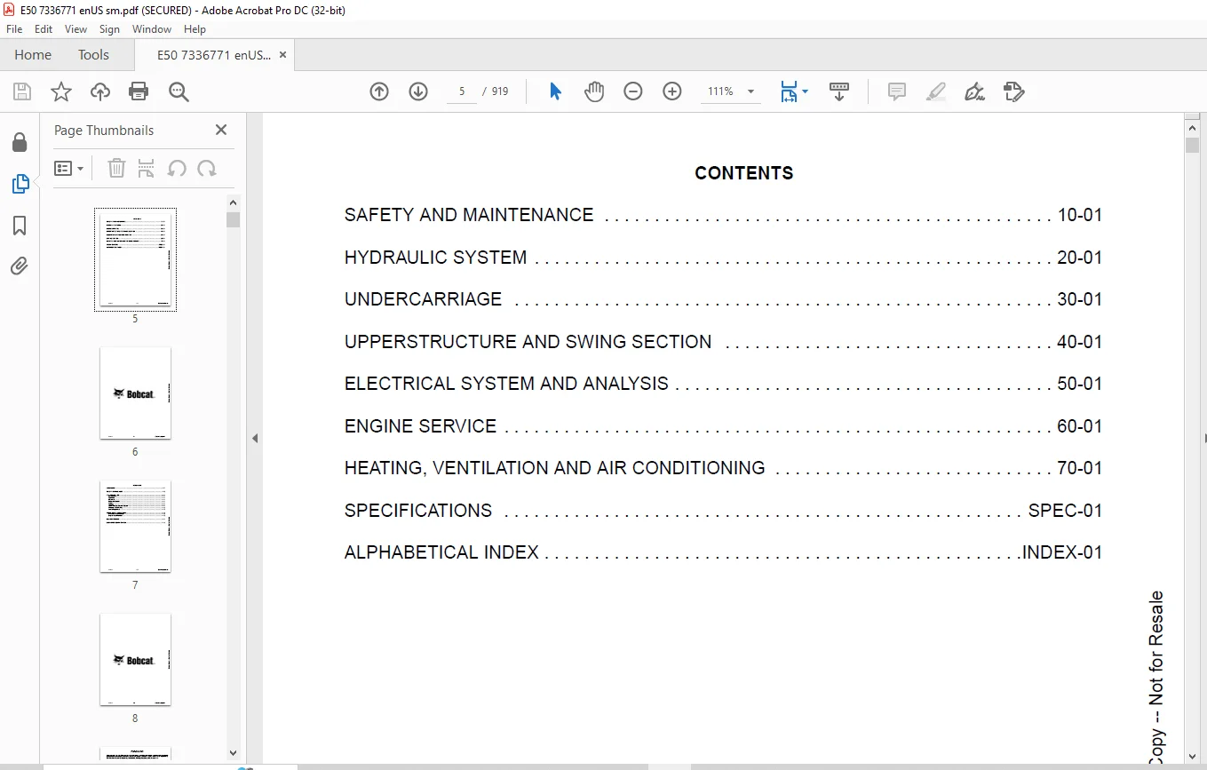
MAINTENANCE SAFETY 3
CONTENTS 5
FOREWORD 7
FOREWORD 9
SAFETY INSTRUCTIONS 11
FIRE PREVENTION 13
Maintenance 13
Operation 13
Electrical 13
Hydraulic System 13
Fueling 13
Starting 13
Spark Arrester Exhaust System 13
Welding And Grinding 14
Fire Extinguishers 14
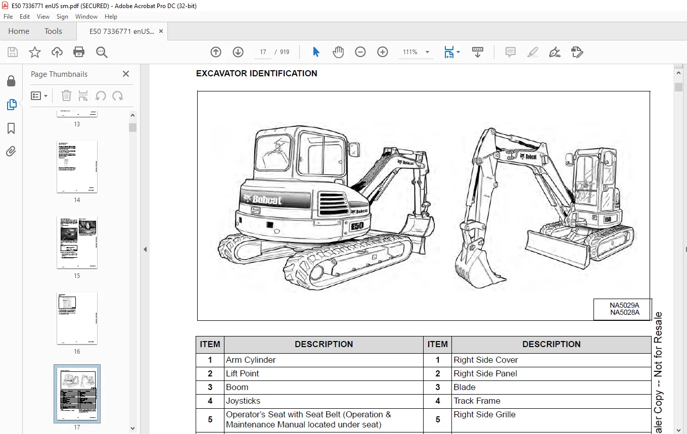
SERIAL NUMBER LOCATIONS 15
Excavator Serial Number 15
Engine Serial Number 15
DELIVERY REPORT 16
EXCAVATOR IDENTIFICATION 17
SAFETY AND MAINTENANCE 19
LIFTING AND BLOCKING THE EXCAVATOR 21
Procedure 21
LIFTING THE EXCAVATOR 23
Procedure 23
OPERATOR CAB (ROPS / TOPS / FOPS) 25
Description 25
Cab Door 26
Front Window 27
Front Wiper 28
Window Washer Reservoir 28
Right Side Windows 29
OPERATOR CANOPY (ROPS / TOPS / FOPS) 31
Description 31
TRANSPORTING THE EXCAVATOR ON A TRAILER 33
Loading And Unloading 33
Fastening 34
TAILGATE 35
Opening And Closing 35
Adjusting The Latch 35
RIGHT SIDE COVER 37
Opening And Closing 37
SERVICE SCHEDULE 39
Maintenance Intervals 39
Service Schedule 39
AIR CLEANER SERVICE 43
Replacing The Filter Elements 43
CAB FILTERS 45
Cleaning And Maintenance 45
ENGINE COOLING SYSTEM 47
Cleaning 47
Checking Level 48
Removing And Replacing Coolant (Cab Models) 49
Removing And Replacing Coolant (Canopy Models) 50
FUEL SYSTEM 53
Fuel Specifications 53
Biodiesel Blend Fuel 53
Filling The Fuel Tank 54
Fuel Filters 55
Draining The Fuel Tank 57
Replacing The Fuel Pre-Filter 58
Replacing The Fuel Tank Vent Filter 59
ENGINE LUBRICATION SYSTEM 61
Checking And Adding Engine Oil 61
Engine Oil Chart 61
Removing And Replacing Oil And Filter 62
HYDRAULIC SYSTEM 63
Checking And Adding Hydraulic Oil 63
Hydraulic / Hydrostatic Fluid Chart 64
Removing And Replacing The Hydraulic Filters 64
Removing And Replacing The Hydraulic Fluid 66
MACHINE LUBRICATION 69
Grease Fitting Locations 69
PIVOT PINS 71
Inspection And Maintenance 71
TRAVEL MOTOR 73
Checking And Adding Oil 73
Removing And Replacing Oil 73
EMERGENCY EXIT 75
Right Side Rear Window 75
Front Window 75
SEAT BELT 77
Inspection And Maintenance 77
CONTROL CONSOLE LOCKOUTS 79
Inspection And Maintenance 79
TOWING THE EXCAVATOR 81
Procedure 81
REMOTE START TOOL (SERVICE TOOL) KIT – 7217666 83
Description 83
Remote Start Tool (Service Tool) – 7022042 84
Excavator Service Tool Harness – 6689747 85
Computer Service Tool Harness – 6689746 86
HYDRAULIC SYSTEM 87
HYDRAULIC / HYDROSTATIC SCHEMATICS 93
HYDRAULIC SYSTEM INFORMATION 95
Glossary Of Hydraulic / Hydrostatic Symbols 95
Troubleshooting The Hydraulic Circuit 98
Troubleshooting The Cylinder Circuit 99
Troubleshooting The Swing (Upperstructure Slew) Circuit 100
Troubleshooting The Travel Circuit 101
CYLINDER (BOOM) 103
Testing 103
Removal And Installation 105
Parts Identification 108
Disassembly 109
Assembly 112
CYLINDER (ARM) 117
Testing 117
Removal And Installation 119
Parts Identification 121
Disassembly 122
Assembly 124
CYLINDER (BOOM SWING) 129
Testing 129
Removal And Installation 131
Parts Identification 133
Disassembly 134
Assembly 136
CYLINDER (BUCKET) 139
Testing 139
Removal And Installation 141
Parts Identification 143
Disassembly 144
Assembly 146
CYLINDER (BLADE) 149
Testing 149
Removal And Installation 151
Parts Identification 152
Disassembly 153
Assembly 155
CYLINDER (CLAMP) 159
Testing 159
Removal And Installation 160
Parts Identification 162
Disassembly 163
Assembly 165
CYLINDER (ANGLE BLADE) 169
Testing 169
Removal And Installation 170
Parts Identification 172
Disassembly 173
Assembly 175
VALVE (MAIN RELIEF) 179
Testing And Adjusting 179
VALVE (PORT RELIEF) 181
Testing And Adjusting 181
VALVE (CROSS PORT RELIEF) 183
Testing And Adjusting 183
Removal And Installation 186
VALVE (PRESSURE REDUCING) 187
Testing And Adjusting 187
HYDRAULIC CONTROL VALVE 189
Description 189
Removal And Installation 189
Parts Identification 193
Disassembly And Assembly 194
Inlet Valve Section Disassembly And Assembly 198
Boom Swing Valve Section Disassembly And Assembly 201
Slew Valve Section Disassembly And Assembly 204
Blade Valve Section Disassembly And Assembly 207
Right And Left Travel Valve Section Disassembly And Assembly 210
Angle Blade Valve Section Disassembly And Assembly 213
Boom, Auxiliary, Arm, And Bucket Valve Section Disassembly And Assembly 216
HYDRAULIC PUMP 219
Hydraulic Pump Work Sheet 219
Pump Testing 222
Removal And Installation 231
Coupler Removal And Installation 232
Hydraulic Pump Startup 233
Torque Limiter Assembly Parts Identification 234
Torque Limiter Assembly Removal And Installation 235
Torque Limiter Valve Assembly Disassembly And Assembly 235
Pump Control Parts Identification 236
Pump Control Removal And Installation 237
Pump Control Disassembly And Assembly 237
MANIFOLD ASSEMBLY / ACCUMULATOR (WITHOUT ANGLE BLADE) 245
Description 245
Removal And Installation 245
Parts Identification 247
Disassembly And Assembly 248
MANIFOLD ASSEMBLY / ACCUMULATOR (WITH ANGLE BLADE) 255
Description 255
Removal And Installation 255
Parts Identification 257
Disassembly And Assembly 258
TRAVEL MOTOR 265
Removal And Installation 265
Parts Identification Hydraulic Motor 266
Parts Identification Gear Reduction Hub 267
Disassembly 268
Assembly 276
SWIVEL JOINT 285
Removal And Installation 285
Parts Identification Straight Blade Swivel 287
Disassembly And Assembly 288
SWIVEL JOINT (WITH ANGLE BLADE) 291
Removal And Installation 291
Parts Identification Angle Blade Swivel 293
Disassembly And Assembly 294
SWING MOTOR 297
Removal And Installation 297
Parts Identification 299
Disassembly And Assembly 300
SWING MOTOR (DRIVE CARRIER) 309
Removal And Installation 309
Parts Identification 310
Disassembly And Assembly 311
CONTROL PATTERN SELECTOR VALVE 317
Removal And Installation 317
Parts Identification 318
Disassembly And Assembly 319
RIGHT CONTROL LEVER (JOYSTICK) 321
Testing 321
Handle Removal And Installation 322
Joystick Assembly Removal And Installation 324
Parts Identification 325
Disassembly 326
Assembly 330
LEFT CONTROL LEVER (JOYSTICK) 335
Testing 335
Handle Removal And Installation 336
Joystick Assembly Removal And Installation 338
Parts Identification 339
Disassembly 340
Assembly 344
HYDRAULIC FILTER MOUNT 349
Removal And Installation 349
HYDRAULIC RESERVOIR 351
Removal And Installation 351
OIL COOLER 353
Description 353
Removal And Installation 353
BLADE CONTROL LEVER 355
Handle Removal And Installation 355
Removal And Installation 356
Parts Identification 357
Disassembly And Assembly 358
CASE DRAIN FILTER MOUNT 363
Removal And Installation 363
TRAVEL CONTROL VALVE 365
Removal And Installation 365
Parts Identification 366
Disassembly And Assembly 367
REMOVING AIR FROM THE HYDRAULIC SYSTEM 373
Procedure 373
MANIFOLD (HYDRAULIC X-CHANGE) 375
Removal And Installation 375
Parts Identification 376
Disassembly And Assembly 377
MANIFOLD (PIN GRABBER) 383
Removal And Installation 383
Parts Identification 384
Disassembly And Assembly 385
SECONDARY AUXILIARY VALVE 387
Removal And Installation 387
Parts Identification 389
Disassembly And Assembly 390
VALVE (BOOM LOCK) 393
Removal And Installation 393
VALVE (ARM LOCK) 395
Removal And Installation 395
UNDERCARRIAGE 397
BLADE 399
Removal And Installation 399
BLADE (ANGLE) 401
Removal And Installation 401
Cutting Edge Removal And Installation 402
TRACK UNDERCARRIAGE COMPONENTS (RUBBER TRACK) 403
Description 403
Track Lug Height 403
Checking / Adjusting Tension 404
Track Removal And Installation 406
Idler Removal And Installation 407
Idler Parts Identification 408
Idler Disassembly 409
Idler Assembly 411
Track Tensioner Removal And Installation 414
Track Tensioner Parts Identification 415
Track Tensioner Disassembly And Assembly 416
Roller Removal And Installation 418
Sprocket Removal And Installation 419
TRACK UNDERCARRIAGE COMPONENTS (STEEL TRACK) 421
Description 421
Checking / Adjusting Tension 422
Track Removal 424
Track Installation 427
Idler Removal And Installation 429
Idler Parts Identification 430
Idler Disassembly 431
Idler Assembly 433
Track Tensioner Removal And Installation 436
Track Tensioner Parts Identification 437
Track Tensioner Disassembly And Assembly 438
Roller Removal And Installation 440
Sprocket Removal And Installation 441
Guide Plate Removal And Installation 441
TRACK MAINTENANCE 443
Track Damage Identification 443
SWING CIRCLE GEAR 455
Swing Bearing Removal 455
Swing Bearing Installation 456
UPPERSTRUCTURE AND SWING SECTION 457
UPPERSTRUCTURE 461
Removal 461
Installation 463
ROPS CANOPY 465
Removal And Installation 465
CAB 469
Removal And Installation 469
Door Removal And Installation 473
Door Latch Removal And Installation 474
Hold Open Latch Removal And Installation 476
Front Window Removal And Installation 478
Front Window Disassembly And Assembly 479
Front Window Adjustment 481
Right Side Rear Sliding Window Removal And Installation 483
Glass Removal 484
SEAT 487
Removal And Installation 487
RIGHT CONSOLE 489
Console Cover Removal And Installation 489
LEFT CONSOLE 493
Lower Console Cover Removal And Installation 493
Upper Console Cover Removal And Installation 493
Compression Spring Removal And Installation 496
Lock Lever Removal And Installation 498
Console Removal And Installation 498
LEFT UPPERSTRUCTURE COVER 499
Removal And Installation 499
RIGHT UPPERSTRUCTURE COVER 501
Removal And Installation 501
COUNTERWEIGHT 503
Removal And Installation 503
Add-On Counterweight Removal And Installation 506
TRAVEL LEVERS AND PEDALS 507
Removal And Installation 507
Disassembly And Assembly 508
FLOORPLATE 509
Removal And Installation 509
FUEL TANK 511
Removal And Installation 511
HORN 513
Removal And Installation 513
SWING FRAME 515
Removal And Installation 515
Boom Swing Frame Hose Routing 518
Bushing Removal 519
Bushing Installation 520
BOOM 521
Removal And Installation 521
STANDARD AND LONG ARM 523
Removal And Installation 523
Arm To Boom Bushing Removal And Installation 524
Arm To Bucket And Bucket Link Bushing Removal And Installation 525
BUCKET 527
Bucket Teeth Removal And Installation 527
Bucket Side Cutting Edge Removal And Installation 528
CLAMP 529
Removal And Installation 529
TAILGATE 531
Removal And Installation 531
Latch Removal And Installation 532
X-CHANGE 533
Removal And Installation 533
Disassembly 534
Assembly 535
X-CHANGE (HYDRAULIC) 537
Removal And Installation 537
Parts Identification 539
Disassembly 540
Assembly 545
QUICK COUPLER (KLAC™ SYSTEM) 553
Troubleshooting 553
Daily Inspection 553
Removal And Installation 554
Parts Identification 556
Disassembly 557
Assembly 559
QUICK COUPLER (GERMAN STYLE) 561
Troubleshooting 561
Daily Inspection 561
Removal (MS03 And MS08) 562
Installation (MS03 And MS08) 563
Parts Identification (MS03) 564
Disassembly And Assembly (MS03) 565
Parts Identification (MS08) 566
Disassembly (MS08) 567
Assembly (MS08) 570
QUICK COUPLER (PIN GRABBER) 575
Troubleshooting 575
Daily Inspection 576
Removal And Installation 576
Parts Identification 578
Disassembly And Assembly 579
RIGHT SIDE COVER 581
Removal And Installation 581
Latch Removal And Installation 582
TOOL BOX 583
Removal And Installation 583
LEFT SIDE GRILLE 585
Removal And Installation 585
LEFT SIDE PANEL 587
Removal And Installation 587
RIGHT SIDE GRILLE 589
Removal And Installation 589
ELECTRICAL SYSTEM AND ANALYSIS 591
ELECTRICAL SCHEMATICS 593
ELECTRICAL SYSTEM INFORMATION 614
Troubleshooting Chart 614
Description 615
Fuse And Relay Location / Identification 615
BATTERY 618
Servicing 618
Maintaining Battery Charge Level 618
Battery Service During Machine Storage 618
Battery Testing 619
Battery Charging 619
Removing And Installing 620
Using A Booster Battery (Jump Starting) 621
ALTERNATOR 622
Belt Adjustment 622
Belt Replacement 622
Charging System Inspection 624
Alternator Voltage Testing 625
Low Voltage Testing 625
High Voltage Testing 626
Removal And Installation 627
Parts Identification 628
STARTER 630
Testing 630
Removal And Installation 631
Parts Identification 632
LIGHTS 634
Removal And Installation 634
Boom Light Removal And Installation 636
Boom Light Bulb Replacement 637
MAGNETIC LOCKOUT SENSOR 638
Removal And Installation 638
FUEL LEVEL SENDER 640
Removal And Installation 640
Testing 642
DIAGNOSTIC SERVICE CODES 644
Viewing Service Codes 644
Service Codes List 646
CONTROL PANEL SETUP 656
Panel Setup (Touch Display) 656
STANDARD DISPLAY 668
Removal And Installation 668
TOUCH DISPLAY 670
Removal And Installation 670
Controller Display Removal And Installation 670
CONTROLLER (GATEWAY AND AUXILIARY) 672
Description 672
Gateway Controller Removal And Installation 672
Auxiliary Controller Removal And Installation 673
ENGINE CONTROL UNIT (ECU) 674
Description 674
Cleaning 675
Removal And Installation 676
KEY SWITCH 680
Removal And Installation 680
WIPER MOTOR 682
Removal And Installation 682
MOTION ALARM SYSTEM 684
Description 684
Inspecting 684
Switch Removal And Installation 685
SERVICE PC (LAPTOP COMPUTER) 686
Connecting The Remote Start Tool 686
Connecting Remote Start Tool (Service Tool) 686
SHUT-OFF SWITCH (IF EQUIPPED) 688
Description 688
Removal And Installation 689
TRAVEL MOTOR AUTO-SHIFT 690
Auto-Shift Drive System 690
Troubleshooting 691
AUTO IDLE PRESSURE SENSOR 694
Description 694
Removal And Installation 695
BOBCAT MACHINE IQ WIRELESS COMMUNICATIONS 696
Description 696
ENGINE SERVICE 700
ENGINE INFORMATION 704
Description 704
Specifications 705
Sensor Location 707
Torque Values 709
Troubleshooting 711
Engine Removal And Installation 713
Compression – Testing (Using Glow Plug Compression Adapter) 721
Compression – Testing (Using Injector Compression Adapter) 723
Injector Signal – Testing 725
Injector Signal – Testing (In-Line) 727
DIESEL OXIDATION CATALYST (DOC) 730
Removal And Installation 730
AIR CLEANER 732
Housing Removal And Installation 732
ENGINE COOLING SYSTEM 734
Description 734
Radiator Cooling Package Removal And Installation 735
Fan Removal And Installation 738
Water Pump Removal And Installation 739
Thermostat Housing Removal And Installation 740
Testing The Thermostat 740
LUBRICATION SYSTEM 742
Description 742
Oil Pan Removal And Installation 743
Oil Pump Removal And Installation 744
Oil Pump Relief Valve Description 745
Oil Pump Relief Valve Removal And Installation 745
Oil Cooler / Oil Filter Module Removal And Installation 745
Oil Cooler / Oil Filter Module Disassembly and Assembly 746
FUEL SYSTEM 748
Description 748
Transfer Pump / High Pressure Pump Removal And Installation 749
Fuel Injector Removal And Installation 751
Lift Pump Removal And Installation 754
Fuel Filter Housing Removal And Installation 755
CYLINDER HEAD 758
Glow Plugs Testing 758
Glow Plug Removal And Installation 759
Cylinder Head Removal And Installation 760
Cylinder Head Disassembly And Assembly 765
Cylinder Head Inspection 766
Cylinder Head Top Clearance 767
Valve Step Height 768
Valve Stem Height 768
Valve Guide 769
Valve 769
Valve Spring 770
Rocker Arm Shaft Disassembly And Assembly 771
Rocker Arm Shaft Inspection 772
Push Rod Inspection 772
CRANKSHAFT AND PISTONS 774
Piston And Connecting Rod Removal And Installation 774
Piston And Connecting Rod Inspection 775
Crankshaft Removal And Installation 777
Cylinder Block Inspection 780
Crankshaft Inspection 782
Connecting Rod Inspection 782
Engine Component Class 783
CAMSHAFT 786
Removal And Installation 786
Inspecting 787
GEARCASE 790
Gearcase Cover Removal And Installation 790
Gear Backlash 791
Gear Timing 792
Idle Gear Removal And Installation 793
Idle Gear Inspection 793
TURBOCHARGER 794
Description 794
Removal And Installation 795
Inspection 796
FLYWHEEL AND HOUSING 798
Hydraulic Pump Coupler Removal And Installation 798
Flywheel Removal And Installation 800
Ring Gear Removal And Installation 800
EXHAUST GAS RECIRCULATION (EGR) SYSTEM 802
EGR Valve Removal And Installation 802
EGR Cooler Removal And Installation 803
INTERCOOLER 804
Description 804
Removal And Installation 804
HEATING, VENTILATION AND AIR CONDITIONING 806
AIR CONDITIONING SYSTEM FLOW 808
Description 808
Chart 809
Components 810
Safety Equipment 813
REGULAR MAINTENANCE 814
Cab Filters 814
Air Conditioning Compressor Belt Adjustment 815
Air Conditioning Compressor Belt Replacement 815
Condenser 816
Air Conditioning Lubrication 816
Evaporator / Heater Coil 816
Air Conditioning Service Chart 818
TROUBLESHOOTING 820
Blower Motor Does Not Operate 820
Blower Motor Operates Normally, But Air Flow Is Insufficient 820
Insufficient Cooling Although Air Flow And Compressor Operation Are Normal 820
The Compressor Operates Improperly Or Not At All 820
Gauge Pressure Related Troubleshooting 821
Temperature / Pressure Chart 822
Poor A/C Performance 823
HVAC Repair And Leaks 823
Electrical System 824
Engine Coolant Bypassing The Heater Valve 826
SYSTEM CHARGING AND RECLAMATION 828
Refrigerant Identification 828
Reclamation And Charging With Recovery / Charging Unit 830
COMPRESSOR 832
Removal And Installation 832
Oil 833
Oil Check 834
CONDENSER 836
Removal And Installation 836
RECEIVER / DRIER 838
Receiver / Drier Removal And Installation 838
Pressure Switch Removal And Installation 839
EVAPORATOR / HEATER UNIT 840
Removal And Installation 840
THERMOSTAT 842
Description 842
Removal And Installation 843
AIR SENSOR 846
Location 846
Inside And After Air Sensor Removal And Installation 847
EXPANSION VALVE 848
Removal And Installation 848
EVAPORATOR COIL 850
Removal And Installation 850
AUTO EVAPORATOR COIL 852
Removal And Installation 852
HEATER COIL 854
Removal And Installation 854
AUTO HEATER COIL 856
Removal And Installation 856
BLOWER FAN 858
Removal And Installation 858
AUTO BLOWER FAN 860
Removal And Installation 860
HEATER VALVE 862
Removal And Installation 862
Control Panel 864
Removal And Installation 864
HVAC DUCT 866
Removal And Installation 866
AUTO HVAC 868
Description 868
ATM Removal And Installation 868
ATM Diagnostic Codes 869
Blower Fan Drive Assembly Removal And Installation 870
De-Icing Sensor Removal And Installation 871
Inside And After Coil Sensor Testing 871
SPECIFICATIONS 874
EXCAVATOR SPECIFICATIONS 876
Machine Dimensions 876
Performance 882
Controls 882
Engine 883
Hydraulic System 884
Hydraulic Cylinders 885
Hydraulic Cycle Times 885
Electrical 886
Drive System 886
Slew System 886
Undercarriage 886
Capacities 887
Tracks 887
Ground Pressure 887
TECHNICAL SERVICE GUIDE SPECIFICATIONS 888
Engine 888
Engine Torques 888
Cooling System 888
Excavator Torques 888
TORQUE SPECIFICATION FOR BOLTS 890
Torque For General SAE Bolts 890
Torque For General Metric Bolts 891
HYDRAULIC CONNECTION SPECIFICATIONS 892
O-ring Face Seal Connection 892
Straight Thread O-ring Fitting 892
Tubelines And Hoses 893
Flare Fitting 893
O-ring Flare Fitting 894
Port Seal Fitting 896
Push To Connect Fittings 897
HYDRAULIC FLUID SPECIFICATIONS 900
Specifications 900
CONVERSIONS 902
Decimal And Millimeter Equivalent Chart 902
U S To Metric Conversion Chart 903
SERVICE TOOLS REQUIRED 904
Remote Start Tools 904
Hydraulic Tools 905
Engine Tools 908
Electrical Tools 910
General Tools 911
HVAC Tools 912
ALPHABETICAL INDEX 914
Questions? Email us: [email protected]
https://vimeo.com/841774531?share=copy
PLEASE NOTE:
- This is the SAME MANUAL used by the dealerships to diagnose your vehicle
- No waiting for couriers / posts as this is a PDF manual and you can download it within 2 minutes time once you make the payment.
- Your payment is all safe and the delivery of the manual is INSTANT – You will be taken to the DOWNLOAD PAGE.
- So have no hesitations whatsoever and write to us about any queries you may have : heydownloadss @gmail.com
S.M