Bobcat E42 Compact Excavator Service Manual – PDF DOWNLOAD
$35.95
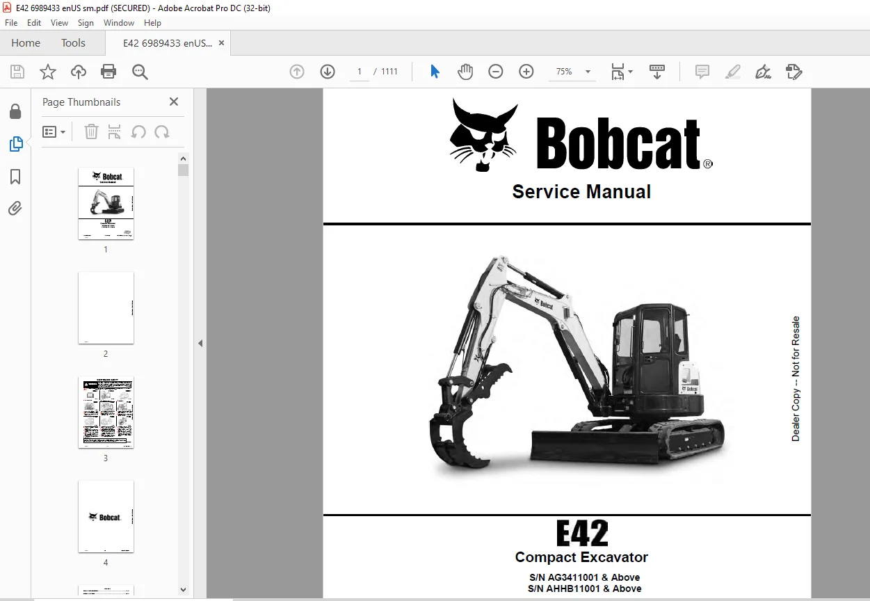
Bobcat E42 Compact Excavator Service Manual – PDF DOWNLOAD
S/N AG3411001 & Above
S/N AHHB11001 & Above
Description
Bobcat E42 Compact Excavator Service Manual – PDF DOWNLOAD
FILE DETAILS:
Bobcat E42 Compact Excavator Service Manual – PDF DOWNLOAD
Language : English
Pages :1111
Downloadable : Yes
File Type : PDF
DESCRIPTION:
Bobcat E42 Compact Excavator Service Manual – PDF DOWNLOAD
FOREWORD
This manual is for the Bobcat excavator mechanic. It provides necessary servicing and adjustment procedures for the Bobcat excavator and its component parts and systems. Refer to the Operation & Maintenance Manual for operating instructions, starting procedure, daily checks, etc.
SAFETY INSTRUCTIONS
Instructions are necessary before operating or servicing machine. Read and understand the Operation & Maintenance Manual, Operator’s Handbook and signs (decals) on machine. Follow warnings and instructions in the manuals when making repairs, adjustments or servicing. Check for correct function after adjustments, repairs or service. Untrained operators and failure to follow instructions can cause injury or death.
The following publications provide information on the safe use and maintenance of the Bobcat machine and attachments:
- The Delivery Report is used to assure that complete instructions have been given to the new owner and that the machine is in safe operating condition.
- The Operation & Maintenance Manual delivered with the machine or attachment contains operating information as well as routine maintenance and service procedures. It is a part of the machine and can be stored in a container provided on the machine. Replacement Operation & Maintenance Manuals can be ordered from your Bobcat dealer.
- Machine signs (decals) instruct on the safe operation and care of your Bobcat machine or attachment. The signs and their locations are shown in the Operation & Maintenance Manual. Replacement signs are available from your Bobcat dealer.
- An Operator’s Handbook fastened to the operator cab. It’s brief instructions are convenient to the operator. The handbook is available from your dealer in an English edition or one of many other languages. See your Bobcat dealer for more information on translated versions.
- The AEM Safety Manual delivered with the machine gives general safety information.
- The Service Manual and Parts Manual are available from your dealer for use by mechanics to do shoptype service and repair work.
IMAGES PREVIEW OF THE MANUAL:
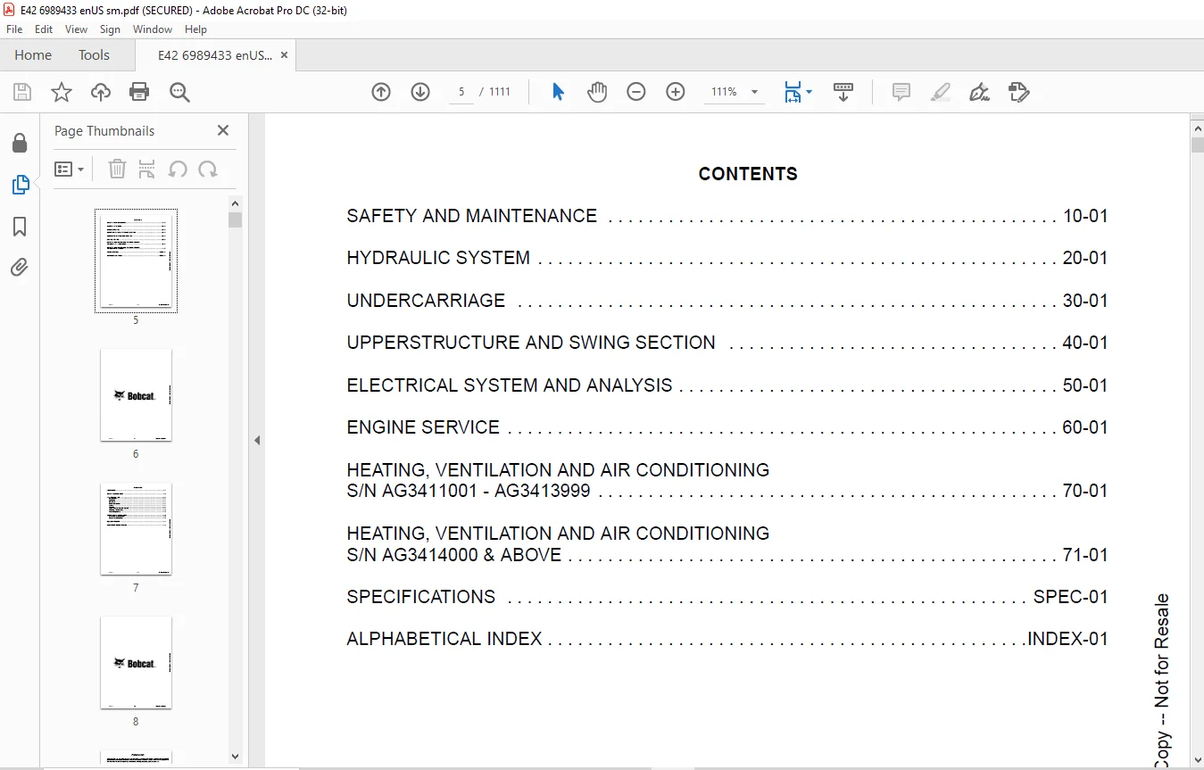
TABLE OF CONTENTS:
Bobcat E42 Compact Excavator Service Manual – PDF DOWNLOAD
MAINTENANCE SAFETY 3
CONTENTS 5
FOREWORD 7
FOREWORD 9
SAFETY INSTRUCTIONS 11
FIRE PREVENTION 13
Maintenance 13
Operation 13
Electrical 13
Hydraulic System 13
Fueling 13
Starting 13
Spark Arrester Exhaust System 13
Welding And Grinding 14
Fire Extinguishers 14
SERIAL NUMBER LOCATIONS 15
Excavator Serial Number 15
Engine Serial Number 15
DELIVERY REPORT 16
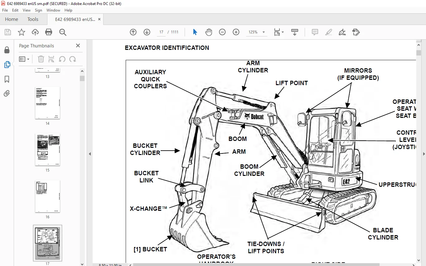
EXCAVATOR IDENTIFICATION 17
SAFETY AND MAINTENANCE 19
LIFTING AND BLOCKING THE EXCAVATOR 23
Procedure 23
LIFTING THE EXCAVATOR 25
Procedure 25
OPERATOR CAB (ROPS / TOPS) 27
Description 27
Cab Door 28
Front Window 29
Front Wiper 30
Window Washer Reservoir 30
Right Side Windows 31
Heating, Ventilation, And Air Conditioning Ducting 33
OPERATOR CANOPY (ROPS / TOPS) 35
Description 35
TRANSPORTING THE EXCAVATOR ON A TRAILER 37
Loading And Unloading 37
Fastening 37
TAILGATE 39
Opening And Closing 39
Adjusting The Latch 39
RIGHT SIDE COVER 41
Opening And Closing 41
SERVICE SCHEDULE 43
Maintenance Intervals 43
AIR CLEANER SERVICE 45
Daily Check 45
Replacing The Filters 45
CAB FILTERS (S/N AG3411001 – AG3413999) 47
Cleaning And Maintenance 47
CAB FILTERS (S/N AG3414000 & ABOVE) 49
Cleaning And Maintenance 49
ENGINE COOLING SYSTEM 51
Cleaning 51
Checking Level 52
Removing And Replacing Coolant 53
FUEL SYSTEM 55
Fuel Specifications 55
Biodiesel Blend Fuel 55
Filling The Fuel Tank 56
Fuel Filters 57
Draining The Fuel Tank 57
Removing Air From The Fuel System 58
ENGINE LUBRICATION SYSTEM 59
Checking And Adding Engine Oil 59
Engine Oil Chart 59
Removing And Replacing Oil And Filter 60
HYDRAULIC SYSTEM 61
Checking And Adding Hydraulic Oil 61
Hydraulic / Hydrostatic Fluid Chart 62
Removing And Replacing The Hydraulic Filters 62
Removing And Replacing The Hydraulic Fluid 64
LUBRICATING THE EXCAVATOR (EARLIER MODELS) 65
Lubrication Locations 65
LUBRICATING THE EXCAVATOR (LATER MODELS) 69
Lubrication Locations 69
PIVOT PINS 73
Inspection And Maintenance 73
TRAVEL MOTOR 75
Checking And Adding Oil 75
Removing And Replacing Oil 75
SPARK ARRESTER MUFFLER 77
Cleaning Procedure 77
EMERGENCY EXIT 79
Right Side Rear Window 79
Front Window 79
SEAT BELT 81
Inspection And Maintenance 81
CONTROL CONSOLE LOCKOUTS 83
Inspection And Maintenance 83
TOWING THE EXCAVATOR 85
Procedure 85
REMOTE START TOOL KIT – MEL1563 87
Remote Start Tool – MEL1563 87
Service Tool Harness Communicator – MEL1566 89
REMOTE START TOOL (SERVICE TOOL) KIT – 7217666 91
Description 91
Remote Start Tool (Service Tool) – 7022042 92
Excavator Service Tool Harness – 6689747 93
Computer Service Tool Harness – 6689746 94
HYDRAULIC SYSTEM 95
HYDRAULIC / HYDROSTATIC SCHEMATICS 101
HYDRAULIC SYSTEM INFORMATION 107
Glossary Of Hydraulic / Hydrostatic Symbols 107
Troubleshooting The Hydraulic Circuit 110
Troubleshooting The Cylinder Circuit 111
Troubleshooting The Swing (Upperstructure Slew) Circuit 112
Troubleshooting The Travel Circuit 113
CYLINDER (BOOM) (S/N AG3411031 & ABOVE, AHHB11002 & ABOVE) 115
Testing 115
Removal And Installation 117
Parts Identification 120
Disassembly 121
Assembly 124
CYLINDER (BOOM) (S/N AG3411030 & BELOW, AHHB11001 & BELOW) 129
Testing 129
Removal And Installation 131
Parts Identification 134
Disassembly 135
Assembly 138
CYLINDER (ARM) 143
Testing 143
Removal And Installation 145
Parts Identification 147
Disassembly 148
Assembly 150
CYLINDER (BOOM SWING) 155
Testing 155
Removal And Installation 157
Parts Identification 160
Disassembly 161
Assembly 163
CYLINDER (BUCKET) 167
Testing 167
Removal And Installation 169
Parts Identification 171
Disassembly 172
Assembly 174
CYLINDER (BLADE) 177
Testing 177
Removal And Installation 179
Parts Identification 180
Disassembly 181
Assembly 183
CYLINDER (CLAMP) 187
Testing 187
Removal And Installation 188
Parts Identification 190
Disassembly 191
Assembly 194
CYLINDER (ANGLE BLADE) 199
Testing 199
Removal And Installation 200
Parts Identification 202
Disassembly 203
Assembly 205
CYLINDER (EXTENDABLE ARM) 209
Testing 209
Parts Identification 211
Disassembly 212
Assembly 214
VALVES (MAIN RELIEF) 219
Testing And Adjusting 219
VALVES (PORT RELIEF) 221
Testing And Adjusting Port Relief Valve Pressure 221
VALVES (CROSS PORT RELIEF) 223
Testing 223
Removal And Installation 226
Cross Port Relief Valve Disassembly And Assembly 226
VALVES (PRESSURE REDUCING) 227
Testing And Adjusting 227
HYDRAULIC CONTROL VALVE 229
Description 229
Removal And Installation 229
Parts Identification 233
Disassembly And Assembly 234
Inlet Valve Section Disassembly And Assembly 238
Boom Swing Valve Section Disassembly And Assembly 242
Slew Valve Section Disassembly And Assembly 245
Blade Valve Section Disassembly And Assembly 249
Right And Left Travel Valve Section Disassembly And Assembly 253
Angle Blade, Boom, Auxiliary, Arm And Bucket Valve Section Disassembly And Assembly 255
HYDRAULIC PUMP 259
Hydraulic Pump Work Sheet 259
Pump Testing 262
Removal And Installation 271
Coupler Removal And Installation 272
Hydraulic Pump Startup 273
Torque Limiter Assembly Parts Identification 274
Torque Limiter Assembly Removal And Installation 275
Torque Limiter Valve Assembly Disassembly And Assembly 275
Pump Control Parts Identification 276
Pump Control Removal And Installation 277
Pump Control Disassembly And Assembly 277
Parts Identification 283
Disassembly And Assembly 284
MANIFOLD ASSEMBLY / ACCUMULATOR (WITHOUT ANGLE BLADE) 293
Description 293
Removal And Installation 293
Parts Identification 295
Disassembly And Assembly 296
MANIFOLD ASSEMBLY / ACCUMULATOR (WITH ANGLE BLADE) 303
Description 303
Removal And Installation 303
Parts Identification 305
Disassembly And Assembly 306
TRAVEL MOTOR 313
Removal And Installation 313
Parts Identification Hydraulic Motor 314
Parts Identification Gear Reduction Hub 315
Disassembly 316
Assembly 326
TRAVEL MOTOR (S/N AG3416000 & Above) 339
Removal And Installation 339
Parts Identification Hydraulic Motor 340
Parts Identification Gear Reduction Hub 341
Disassembly 342
Assembly 350
SWIVEL JOINT 359
Removal And Installation 359
Parts Identification Angle Blade Swivel (S/N AG3411001 – AG3414791) 361
Parts Identification Angle Blade Swivel (AG3414792 – AG3414817) 362
Parts Identification Angle Blade Swivel (S/NAG3414818 & Above) 363
Parts Identification Straight Blade Swivel (S/N AG3411001 – AG3414790) 364
Parts Identification Straight Blade Swivel (AG3414791 – AG3414817) 365
Parts Identification Straight Blade Swivel (S/N AG3414818 & Above) 366
Disassembly And Assembly 367
SWING MOTOR (EARLIER MODEL) 369
Removal And Installation 369
Parts Identification 370
Disassembly And Assembly 371
SWING MOTOR (LATER MODEL) 379
Removal And Installation 379
Parts Identification 380
Disassembly And Assembly 381
SWING MOTOR (DRIVE CARRIER) 387
Removal And Installation 387
Parts Identification 388
Disassembly And Assembly 389
CONTROL PATTERN SELECTOR VALVE 395
Removal And Installation 395
Parts Identification 396
Disassembly And Assembly 397
RIGHT CONTROL LEVER (JOYSTICK) (S/N AG3411001 – AG3413999 AND AHHB11001 – AHHB13999) 399
Testing 399
Handle Removal And Installation 400
Joystick Assembly Removal And Installation 402
Parts Identification 403
Disassembly 404
Assembly 409
RIGHT CONTROL LEVER (JOYSTICK) (S/N AG3414001 & ABOVE AND AHHB14001 & ABOVE) 413
Testing 413
Handle Removal And Installation 414
Joystick Assembly Removal And Installation 416
Parts Identification 417
Disassembly 418
Assembly 422
LEFT CONTROL LEVER (JOYSTICK) (S/N AG3411001 – AG3413999 AND AHHB11001 – AHHB13999) 427
Testing 427
Handle Removal And Installation 428
Joystick Assembly Removal And Installation 430
Parts Identification 431
Disassembly 432
Assembly 437
LEFT CONTROL LEVER (JOYSTICK) (S/N AG3414001 & ABOVE AND AHHB14001 & ABOVE) 441
Testing 441
Handle Removal And Installation 442
Joystick Assembly Removal And Installation 444
Parts Identification 445
Disassembly 446
Assembly 450
HYDRAULIC FILTER MOUNT 455
Removal And Installation 455
HYDRAULIC RESERVOIR 457
Removal And Installation 457
OIL COOLER 459
Removal And Installation 459
DIRECT TO TANK VALVE 461
Removal And Installation 461
BLADE CONTROL LEVER 463
Handle Removal And Installation 463
Removal And Installation 465
Parts Identification 467
Disassembly And Assembly 468
CASE DRAIN FILTER MOUNT 473
Removal And Installation 473
TRAVEL CONTROL VALVE 475
Removal And Installation 475
Parts Identification 476
Disassembly And Assembly 477
REMOVING AIR FROM THE HYDRAULIC SYSTEM 483
Procedure 483
MANIFOLD (HYDRAULIC X-CHANGE) (EARLIER MODELS) 485
Removal And Installation 485
Parts Identification 486
Disassembly And Assembly 487
MANIFOLD (HYDRAULIC X-CHANGE) (LATER MODELS) 491
Removal And Installation 491
Parts Identification 492
Disassembly And Assembly 493
MANIFOLD (PIN GRABBER) 499
Removal And Installation 499
Parts Identification 500
Disassembly And Assembly 501
SECONDARY AUXILIARY VALVE (EARLIER MODELS) 503
Removal And Installation 503
Parts Identification 505
Disassembly And Assembly 506
SECONDARY AUXILIARY VALVE (LATER MODELS) 511
Removal And Installation 511
Parts Identification 513
Disassembly And Assembly 514
VALVE (BOOM LOCK) 517
Removal And Installation 517
VALVE (ARM LOCK) 519
Removal And Installation 519
UNDERCARRIAGE 521
BLADE 523
Removal And Installation 523
BLADE (ANGLE) 525
Removal And Installation 525
Cutting Edge Removal And Installation 526
TRACK UNDERCARRIAGE COMPONENTS (RUBBER TRACK) 527
Description 527
Track Lug Height 527
Checking Tension 528
Adjusting Tension 529
Track Removal And Installation 531
Idler Removal And Installation 532
Idler Parts Identification 533
Idler Disassembly 534
Idler Assembly 536
Track Tensioner Removal And Installation 539
Track Tensioner Parts Identification 540
Track Tensioner Disassembly And Assembly 541
Roller Removal And Installation 543
Sprocket Removal And Installation 544
TRACK UNDERCARRIAGE COMPONENTS (STEEL TRACK) 545
Description 545
Checking Tension 546
Adjusting Tension 547
Track Removal 549
Track Installation 552
Idler Removal And Installation 554
Idler Parts Identification 555
Idler Disassembly 556
Idler Assembly 558
Track Tensioner Removal And Installation 561
Track Tensioner Parts Identification 562
Track Tensioner Disassembly And Assembly 563
Roller Removal And Installation 565
Sprocket Removal And Installation 566
Guide Plate Removal And Installation 566
TRACK MAINTENANCE 567
Track Damage Identification 567
SWING CIRCLE GEAR 579
Swing Bearing Removal 579
Swing Bearing Installation 580
UPPERSTRUCTURE AND SWING SECTION 581
UPPERSTRUCTURE 585
Removal 585
Installation 587
ROPS CANOPY 589
Removal And Installation 589
CAB 593
Removal And Installation 593
Door Removal And Installation 596
Front Window Removal And Installation (Earlier Models) 597
Front Window Removal And Installation (Later Models) 598
Front Window Disassembly And Assembly (Later Models) 599
Front Window Adjustment (Later Models) 601
Right Side Rear Sliding Window Removal And Installation 603
Right Side Front Sliding Window Removal And Installation 603
Right Side Front And Rear Sliding Window Weather Strip Removal And Installation 604
Right Side Front And Rear Sliding Window Wiper Strip Removal And Installation 604
Glass Removal 605
Glass Installation 606
SEAT 613
Removal And Installation 613
Seat Mount Removal And Installation 614
RIGHT CONSOLE S/N AG3411001 – AG3413999 615
Console Cover Removal And Installation 615
RIGHT CONSOLE S/N AG3414000 & ABOVE 621
Console Cover Removal And Installation 621
LEFT CONSOLE 627
Lower Console Cover Removal And Installation 627
Upper Console Cover Removal And Installation 628
Compression Spring Removal And Installation 630
Lock Lever Removal And Installation 632
Console Removal And Installation 633
LEFT UPPERSTRUCTURE COVER 635
Removal And Installation 635
RIGHT UPPERSTRUCTURE COVER 637
Removal And Installation 637
COUNTERWEIGHT 639
Removal And Installation 639
Long Arm Counterweight Removal And Installation 642
TRAVEL LEVERS AND PEDALS 643
Removal And Installation 643
Disassembly And Assembly 644
FLOOR MAT 645
Removal And Installation 645
FUEL TANK 647
Removal And Installation (Canopy Equipped Excavator) 647
Removal And Installation (Cab Equipped Excavator) 648
Fuel Tank Fitting Removal And Installation 648
HORN 649
Removal And Installation 649
SWING FRAME 651
Removal And Installation 651
Boom Swing Frame Hose Routing 654
Bushing Removal 655
Bushing Installation 656
BOOM 657
Removal And Installation 657
STANDARD AND LONG ARM 659
Removal And Installation 659
Arm To Boom Bushing Removal And Installation 660
Arm To Bucket And Bucket Link Bushing Removal And Installation 661
ARM (EXTENDABLE) 663
Removal And Installation 663
Arm To Boom Bushing Removal And Installation 664
Arm To Bucket Bushing Removal And Installation 665
Disassembly And Assembly 666
Shimming Procedure 673
BUCKET 675
Bucket Teeth Removal And Installation 675
Bucket Side Cutting Edge Removal And Installation 676
CLAMP 677
Removal And Installation 677
TAILGATE 679
Removal And Installation 679
Latch Removal And Installation 680
X-CHANGE 681
Removal And Installation 681
Disassembly 683
Assembly 684
X-CHANGE (HYDRAULIC) Earlier Models 687
Removal And Installation 687
Parts Identification 689
Disassembly 690
Assembly 695
Expansion Plug Installation 703
X-CHANGE (HYDRAULIC) Later model 705
Removal And Installation 705
Parts Identification 707
Disassembly 708
Assembly 713
Expansion Plug Installation 721
QUICK COUPLER (KLAC™ SYSTEM) 723
Troubleshooting 723
Daily Inspection 723
Removal And Installation 724
Parts Identification 726
Disassembly 727
Assembly 729
QUICK COUPLER (LEHNHOFF® SYSTEM) 731
Troubleshooting 731
Daily Inspection 731
Removal (MS03 And MS08) 732
Installation (MS03 And MS08) 733
Parts Identification (MS03) 734
Disassembly And Assembly (MS03) 735
Parts Identification (MS08) 736
Disassembly (MS08) 737
Assembly (MS08) 740
QUICK COUPLER (PIN GRABBER) 745
Troubleshooting 745
Daily Inspection 746
Removal And Installation 746
Parts Identification 748
Disassembly And Assembly 749
RIGHT SIDE COVER (EARLIER MODEL) 751
Removal And Installation 751
Latch Removal And Installation 752
Latch Adjustment 753
RIGHT SIDE COVER (LATER MODEL) 755
Removal And Installation 755
Latch Removal And Installation 756
Adjustment 757
TOOL BOX 759
Removal And Installation 759
ELECTRICAL SYSTEM AND ANALYSIS 761
ELECTRICAL SCHEMATICS 765
ELECTRICAL SYSTEM INFORMATION 774
Troubleshooting Chart 774
Description 775
Fuse And Relay Location / Identification 775
BATTERY 778
Servicing 778
Using A Booster Battery (Jump Starting) 779
Removing And Installing 780
ALTERNATOR 782
Belt Adjustment 782
Belt Replacement 782
Charging System Inspection 784
Alternator Voltage Testing 785
Low Voltage Testing 785
High Voltage Testing 786
Removal And Installation 787
Parts Identification 789
STARTER 790
Testing 790
Removal And Installation 791
Parts Identification 792
LIGHTS 794
Removal And Installation 794
Boom Light Removal And Installation 795
Boom Light Bulb Replacement 795
MAGNETIC LOCKOUT SENSOR 796
Removal And Installation 796
FUEL LEVEL SENDER 798
Removal And Installation 798
Testing 799
DIAGNOSTIC SERVICE CODES (S/N AG3411001 – AG3413999) 800
Number Codes List 800
DIAGNOSTIC SERVICE CODES (S/N AG3414000 & ABOVE) 802
Viewing Service Codes 802
Number Codes List 803
DELUXE INSTRUMENT PANEL SETUP (S/N AG3411001 – AG3413999) 806
Passwords 806
Password Entry (For Starting And Operating The Machine) 806
Changing The Operator Password 806
Password Lockout Feature 807
Job Clock 807
RPM 807
CONTROL PANEL SETUP (S/N AG3414000 & ABOVE) 808
Panel Setup (Deluxe Instrument Panel) 808
Password Setup (Keyless Start Panel) 815
Password Lockout Feature 815
Password Setup (Deluxe Instrument Panel) 816
Maintenance Clock 819
INSTRUMENT PANEL / CONTROLLER (S/N AG3411001 – AG3413999) 822
Removal And Installation 822
INSTRUMENT PANEL (S/N AG3414000 & ABOVE) 824
Removal And Installation 824
CONTROLLER (S/N AG3414000 & ABOVE) (GATEWAY AND AUXILIARY) 826
Description 826
Gateway Controller Removal and Installation 826
Auxiliary Controller Removal And Installation 827
KEY SWITCH 828
Removal And Installation 828
WIPER MOTOR 830
Removal And Installation 830
MOTION ALARM SYSTEM 832
Description 832
Inspecting 832
Adjusting Switch Position 833
SERVICE PC (LAPTOP COMPUTER) 834
Connecting The Remote Start Tool 834
Connecting Remote Start Tool (Service Tool) 834
Operation 835
SHUT-OFF SWITCH 836
Description 836
Removal And Installation 837
TRAVEL MOTOR AUTO-SHIFT 840
Auto-Shift Drive System (If Equipped) 840
Troubleshooting 841
AUTO IDLE PRESSURE SENSOR 844
Description 844
Removal And Installation 845
BOBCAT MACHINE IQ WIRELESS COMMUNICATIONS 846
Description 846
Controller Removal And Installation 846
Antenna Removal And Installation 848
Procedure 850
ENGINE SERVICE 852
ENGINE INFORMATION 854
Description 854
Specifications 855
Crankshaft Re-Grind Data 861
Torque For Kubota Metric Bolts 862
Troubleshooting 863
Removal And Installation 864
Compression Checking 874
ENGINE SPEED CONTROL 876
Removal And Installation 876
Auto Idle Description 877
Auto Idle Controller Removal And Installation 878
Calibration 879
Actuator Removal And Installation 882
MUFFLER 886
Removal And Installation 886
AIR CLEANER 888
Housing Removal And Installation 888
ENGINE COOLING SYSTEM 890
Radiator Removal And Installation 890
Fan Removal And Installation 894
Water Pump Removal And Installation 895
Water Pump Disassembly And Assembly 895
Thermostat Housing Removal And Installation 896
Thermostat – Checking 896
LUBRICATION SYSTEM 898
Oil Pan Removal And Installation 898
Oil Pump Removal And Installation 899
Oil Pump Inspection 899
Engine Oil Pressure – Testing 900
FUEL SYSTEM 902
Fuel Shutoff Solenoid – Checking 902
Fuel Shut-off Solenoid Removal And Installation 903
Fuel Injection Pump – Checking 904
Fuel Injection Pump Removal And Installation 905
Fuel Injection Pump – Timing 908
Fuel Camshaft Removal And Installation 910
Fuel Camshaft Governor 911
Fuel Injector Removal And Installation 912
Fuel Injector Nozzle Pressure – Checking 914
Nozzle Spray Condition 915
Valve Seat Tightness 915
CYLINDER HEAD 916
Glow Plugs – Testing 916
Glow Plugs Removal And Installation 917
Valve Clearance Adjustment 918
Valve Timing – Checking 918
Cylinder Head Removal And Installation 919
Cylinder Head Disassembly And Assembly 922
Cylinder Head – Servicing 923
Cylinder Head Top Clearance 923
Valve Guide – Checking 924
Valve Guide Removal And Installation 925
Reconditioning The Valve And Valve Seat 926
Valve Spring 927
Valve Tappets 928
Rocker Arm And Shaft – Checking 929
Push Rod Alignment – Checking 929
CRANKSHAFT AND PISTONS 930
Piston And Connecting Rod Removal And Installation 930
Piston And Connecting Rod – Servicing 933
Cylinder Bore – Checking 935
Connecting Rod Alignment 936
Crankshaft Gear Removal And Installation 937
Crankshaft And Bearings Removal And Installation 938
Crankshaft And Bearings – Servicing 941
CAMSHAFT AND TIMING GEARS 946
Timing Gearcase Cover Removal And Installation 946
Timing Gears Backlash – Checking 949
Idle Gear And Camshaft Removal And Installation 950
Camshaft – Servicing 952
Idle Gear And Shaft – Servicing 953
FLYWHEEL AND HOUSING 954
Hydraulic Pump Coupler Removal And Installation 954
Flywheel Removal And Installation 956
Flywheel Ring Gear 956
FLYWHEEL RPM SENSOR 958
Description 958
Removal 958
Installation 958
HEATING, VENTILATION AND AIR CONDITIONING S/N AG3411001 – AG3413999 960
AIR CONDITIONING SYSTEM FLOW 962
Description 962
Chart 963
Components 964
Safety Equipment 968
REGULAR MAINTENANCE 970
Cab Filters 970
Air Conditioning Compressor Belt Adjustment 971
Air Conditioning Compressor Belt Replacement 971
Condenser 972
Air Conditioning Lubrication 972
Evaporator / Heater Coil 972
Air Conditioning Service Chart 973
TROUBLESHOOTING 974
Blower Motor Does Not Operate 974
Blower Motor Operates Normally, But Air Flow Is Insufficient 974
Insufficient Cooling Although Air Flow And Compressor Operation Are Normal 974
The Compressor Operates Improperly Or Not At All 974
Gauge Pressure Related Troubleshooting 975
Temperature / Pressure Chart 976
Poor A/C Performance 977
HVAC Repair And Leaks 978
Electrical System 979
Engine Coolant Bypassing The Heater Valve 981
SYSTEM CHARGING AND RECLAMATION 982
Refrigerant Identification 982
Reclamation And Charging With Recovery / Charging Unit 984
COMPRESSOR 986
Removal And Installation 986
Oil 988
Oil Check 989
CONDENSER 992
Removal And Installation 992
RECEIVER / DRIER 994
Receiver / Drier Removal And Installation 994
Pressure Relief Valve Removal And Installation 995
Pressure Switch Removal And Installation 995
EVAPORATOR / HEATER UNIT 996
Removal And Installation 996
THERMOSTAT 998
Description 998
Removal And Installation 999
EXPANSION VALVE 1002
Removal And Installation 1002
EVAPORATOR COIL 1004
Removal And Installation 1004
HEATER COIL 1006
Removal And Installation 1006
BLOWER FAN 1008
Removal And Installation 1008
HEATER VALVE 1010
Removal And Installation 1010
HVAC DUCT 1012
Removal And Installation 1012
HEATING, VENTILATION AND AIR CONDITIONING S/N AG3414000 & ABOVE 1014
AIR CONDITIONING SYSTEM FLOW 1016
Description 1016
Chart 1017
Components 1018
Safety Equipment 1022
REGULAR MAINTENANCE 1024
Cab Filters 1024
Air Conditioning Compressor Belt Adjustment 1026
Air Conditioning Compressor Belt Replacement 1026
Condenser 1027
Air Conditioning Lubrication 1027
Evaporator / Heater Coil 1027
Air Conditioning Service Chart 1029
TROUBLESHOOTING 1030
Blower Motor Does Not Operate 1030
Blower Motor Operates Normally, But Air Flow Is Insufficient 1030
Insufficient Cooling Although Air Flow And Compressor Operation Are Normal 1030
The Compressor Operates Improperly Or Not At All 1030
Gauge Pressure Related Troubleshooting 1031
Temperature / Pressure Chart 1032
Poor A/C Performance 1033
HVAC Repair And Leaks 1034
Electrical System 1035
Engine Coolant Bypassing The Heater Valve 1037
SYSTEM CHARGING AND RECLAMATION 1038
Refrigerant Identification 1038
Reclamation And Charging With Recovery / Charging Unit 1040
COMPRESSOR 1042
Removal And Installation 1042
Oil 1044
Oil Check 1045
CONDENSER 1048
Removal And Installation 1048
RECEIVER / DRIER 1050
Receiver / Drier Removal And Installation 1050
Pressure Relief Valve Removal And Installation 1051
Pressure Switch Removal And Installation 1051
EVAPORATOR / HEATER UNIT 1052
Removal And Installation 1052
THERMOSTAT 1054
Description 1054
Removal And Installation 1055
EXPANSION VALVE 1058
Removal And Installation 1058
EVAPORATOR COIL 1060
Removal And Installation 1060
HEATER COIL 1062
Removal And Installation 1062
BLOWER FAN 1064
Removal And Installation 1064
HEATER VALVE 1066
Removal And Installation 1066
HVAC DUCT 1068
Removal And Installation 1068
SPECIFICATIONS 1070
EXCAVATOR SPECIFICATIONS 1072
Machine Dimensions 1072
Machine Dimensions – Standard Arm 1073
Machine Dimensions – Long Arm 1074
Machine Dimensions – Extendable Arm 1075
Machine Dimensions – Angle Blade 1076
Performance 1077
Controls 1077
Engine 1078
Hydraulic System 1079
Hydraulic Cylinders 1080
Hydraulic Cycle Times 1080
Drive System 1080
Slew System 1080
Undercarriage 1080
Electrical 1081
Capacities 1081
Tracks 1081
Ground Pressure 1082
TORQUE SPECIFICATION FOR BOLTS 1084
Torque For General SAE Bolts 1084
Torque For General Metric Bolts 1085
HYDRAULIC CONNECTION SPECIFICATIONS 1086
O-ring Face Seal Connection 1086
Straight Thread O-ring Fitting 1086
Tubelines And Hoses 1087
Flare Fitting 1087
O-ring Flare Fitting 1088
Port Seal Fitting 1090
Push To Connect Fittings 1091
HYDRAULIC FLUID SPECIFICATIONS 1094
Specifications 1094
CONVERSIONS 1096
Decimal And Millimeter Equivalent Chart 1096
U S To Metric Conversion Chart 1097
SERVICE TOOLS REQUIRED 1098
Remote Start Tools 1098
Hydraulic Tools 1099
Engine Tools 1102
Electrical Tools 1104
General Tools 1104
HVAC Tools 1105
ALPHABETICAL INDEX 1106
Need help? Contact: [email protected]
https://vimeo.com/841785436?share=copy
PLEASE NOTE:
- This is the SAME manual used by the dealers to troubleshoot any faults in your vehicle. This can be yours in 2 minutes after the payment is made.
- Contact us at [email protected] should you have any queries before your purchase or that you need any other service / repair / parts operators manual.
S.M