Bobcat E42 Compact Excavator Service Manual SN B4GM11001 & Above – PDF DOWNLOAD
$34.95
Bobcat E42 Compact Excavator Service Manual SN B4GM11001 & Above – PDF DOWNLOAD
S/N B4GM11001 & Above
Description
Bobcat E42 Compact Excavator Service Manual SN B4GM11001 & Above – PDF DOWNLOAD
FILE DETAILS:
Bobcat E42 Compact Excavator Service Manual SN B4GM11001 & Above – PDF DOWNLOAD
Language : English
Pages : 943
Downloadable : Yes
File Type : PDF
DESCRIPTION:
S/N B4GM11001 & Above
Bobcat E42 Compact Excavator Service Manual SN B4GM11001 & Above – PDF DOWNLOAD
FOREWORD
This manual is for the Bobcat excavator mechanic. It provides necessary servicing and adjustment procedures for the Bobcat excavator and its component parts and systems. Refer to the Operation & Maintenance Manual for operating instructions, starting procedure, daily checks, etc.
SAFETY INSTRUCTIONS
Instructions are necessary before operating or servicing machine. Read and understand the Operation & Maintenance Manual, Operator’s Handbook and signs (decals) on machine. Follow warnings and instructions in the manuals when making repairs, adjustments or servicing. Check for correct function after adjustments, repairs or service. Untrained operators and failure to follow instructions can cause injury or death.
The following publications provide information on the safe use and maintenance of the Bobcat machine and attachments:
- The Delivery Report is used to assure that complete instructions have been given to the new owner and that the machine is in safe operating condition.
- The Operation & Maintenance Manual delivered with the machine or attachment contains operating information as well as routine maintenance and service procedures. It is a part of the machine and can be stored in a container provided on the machine. Replacement Operation & Maintenance Manuals can be ordered from your Bobcat dealer.
- Machine signs (decals) instruct on the safe operation and care of your Bobcat machine or attachment. The signs and their locations are shown in the Operation & Maintenance Manual. Replacement signs are available from your Bobcat dealer.
- An Operator’s Handbook fastened to the operator cab. It’s brief instructions are convenient to the operator. The handbook is available from your dealer in an English edition or one of many other languages. See your Bobcat dealer for more information on translated versions.
- The AEM Safety Manual delivered with the machine gives general safety information.
- The Service Manual and Parts Manual are available from your dealer for use by mechanics to do shoptype service and repair work.
IMAGES PREVIEW OF THE MANUAL:
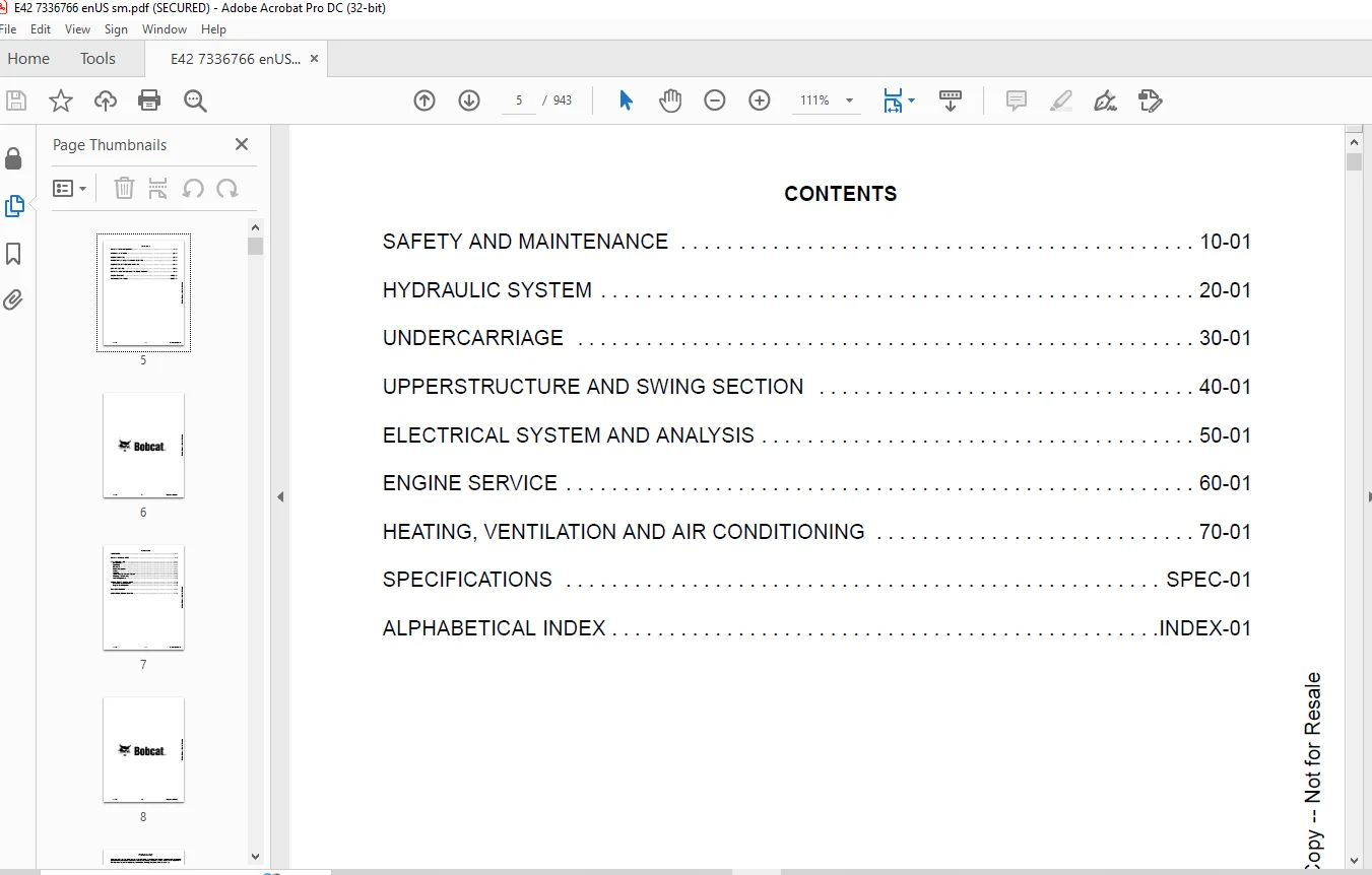
TABLE OF CONTENTS:
Bobcat E42 Compact Excavator Service Manual SN B4GM11001 & Above – PDF DOWNLOAD
MAINTENANCE SAFETY 3
CONTENTS 5
FOREWORD 7
FOREWORD 9
SAFETY INSTRUCTIONS 11
FIRE PREVENTION 13
Maintenance 13
Operation 13
Electrical 13
Hydraulic System 13
Fueling 13
Starting 13
Spark Arrester Exhaust System 13
Welding And Grinding 14
Fire Extinguishers 14
SERIAL NUMBER LOCATIONS 15
Excavator Serial Number 15
Engine Serial Number 15
DELIVERY REPORT 16
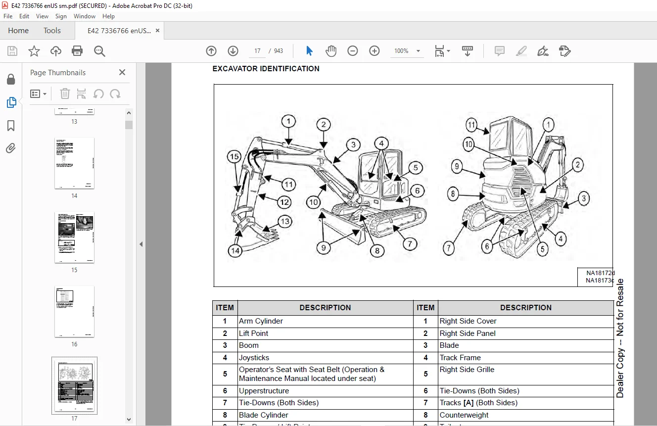
EXCAVATOR IDENTIFICATION 17
SAFETY AND MAINTENANCE 19
LIFTING AND BLOCKING THE EXCAVATOR 21
Procedure 21
LIFTING THE EXCAVATOR 23
Procedure 23
OPERATOR CAB (ROPS / TOPS / FOPS) 25
Description 25
Cab Door 26
Front Window 27
Front Wiper 28
Window Washer Reservoir 28
Right Side Windows 29
OPERATOR CANOPY (ROPS / TOPS / FOPS) 31
Description 31
TRANSPORTING THE EXCAVATOR ON A TRAILER 33
Loading And Unloading 33
Fastening 34
TAILGATE 35
Opening And Closing 35
Adjusting The Latch 35
RIGHT SIDE COVER 37
Opening And Closing 37
SERVICE SCHEDULE 39
Maintenance Intervals 39
Service Schedule 39
AIR CLEANER SERVICE 43
Replacing The Filter Elements 43
CAB FILTERS 45
Cleaning And Maintenance 45
ENGINE COOLING SYSTEM 47
Cleaning 47
Checking Level 48
Removing And Replacing Coolant (Cab Models) 49
Removing And Replacing Coolant (Canopy Models) 50
FUEL SYSTEM 53
Fuel Specifications 53
Biodiesel Blend Fuel 53
Filling The Fuel Tank 54
Fuel Filters 55
Draining The Fuel Tank 57
Replacing The Fuel Pre-Filter 58
Replacing The Fuel Tank Vent Filter 59
ENGINE LUBRICATION SYSTEM 61
Checking And Adding Engine Oil 61
Engine Oil Chart 61
Removing And Replacing Oil And Filter 62
HYDRAULIC SYSTEM 63
Checking And Adding Hydraulic Oil 63
Hydraulic / Hydrostatic Fluid Chart 64
Removing And Replacing The Hydraulic Filters 64
Removing And Replacing The Hydraulic Fluid 66
MACHINE LUBRICATION 69
Grease Fitting Locations 69
PIVOT PINS 71
Inspection And Maintenance 71
TRAVEL MOTOR 73
Checking And Adding Oil 73
Removing And Replacing Oil 73
EMERGENCY EXIT 75
Right Side Rear Window 75
Front Window 75
SEAT BELT 77
Inspection And Maintenance 77
CONTROL CONSOLE LOCKOUTS 79
Inspection And Maintenance 79
TOWING THE EXCAVATOR 81
Procedure 81
REMOTE START TOOL (SERVICE TOOL) KIT – 7217666 83
Description 83
Remote Start Tool (Service Tool) – 7022042 84
Excavator Service Tool Harness – 6689747 85
Computer Service Tool Harness – 6689746 86
HYDRAULIC SYSTEM 87
HYDRAULIC / HYDROSTATIC SCHEMATICS 93
HYDRAULIC SYSTEM INFORMATION 95
Glossary Of Hydraulic / Hydrostatic Symbols 95
Troubleshooting The Hydraulic Circuit 98
Troubleshooting The Cylinder Circuit 99
Troubleshooting The Swing (Upperstructure Slew) Circuit 100
Troubleshooting The Travel Circuit 101
CYLINDER (BOOM) 103
Testing 103
Removal And Installation 105
Parts Identification 108
Disassembly 109
Assembly 112
CYLINDER (ARM) 117
Testing 117
Removal And Installation 119
Parts Identification 121
Disassembly 122
Assembly 124
CYLINDER (BOOM SWING) 129
Testing 129
Removal And Installation 131
Parts Identification 133
Disassembly 134
Assembly 136
CYLINDER (BUCKET) 139
Testing 139
Removal And Installation 141
Parts Identification 143
Disassembly 144
Assembly 146
CYLINDER (BLADE) 149
Testing 149
Removal And Installation 151
Parts Identification 152
Disassembly 153
Assembly 155
CYLINDER (CLAMP) 159
Testing 159
Removal And Installation 160
Parts Identification 162
Disassembly 163
Assembly 165
CYLINDER (ANGLE BLADE) 171
Testing 171
Removal And Installation 172
Parts Identification 174
Disassembly 175
Assembly 177
CYLINDER (EXTENDABLE ARM) 181
Testing 181
Parts Identification 183
Disassembly 184
Assembly 186
VALVE (MAIN RELIEF) 191
Testing And Adjusting 191
VALVE (PORT RELIEF) 193
Testing And Adjusting 193
VALVE (CROSS PORT RELIEF) 195
Testing And Adjusting 195
Removal And Installation 198
VALVE (PRESSURE REDUCING) 199
Testing And Adjusting 199
HYDRAULIC CONTROL VALVE 201
Description 201
Removal And Installation 201
Parts Identification 205
Disassembly And Assembly 206
Inlet Valve Section Disassembly And Assembly 210
Boom Swing Valve Section Disassembly And Assembly 213
Slew Valve Section Disassembly And Assembly 216
Blade Valve Section Disassembly And Assembly 219
Right And Left Travel Valve Section Disassembly And Assembly 222
Angle Blade Valve Section Disassembly And Assembly 225
Boom, Auxiliary, Arm, And Bucket Valve Section Disassembly And Assembly 228
HYDRAULIC PUMP 231
Hydraulic Pump Work Sheet 231
Pump Testing 234
Removal And Installation 243
Coupler Removal And Installation 244
Hydraulic Pump Startup 245
Torque Limiter Assembly Parts Identification 246
Torque Limiter Assembly Removal And Installation 247
Torque Limiter Valve Assembly Disassembly And Assembly 247
Pump Control Parts Identification 248
Pump Control Removal And Installation 249
Pump Control Disassembly And Assembly 249
MANIFOLD ASSEMBLY / ACCUMULATOR (WITHOUT ANGLE BLADE) 255
Description 255
Removal And Installation 255
Parts Identification 257
Disassembly And Assembly 258
MANIFOLD ASSEMBLY / ACCUMULATOR (WITH ANGLE BLADE) 265
Description 265
Removal And Installation 265
Parts Identification 267
Disassembly And Assembly 268
TRAVEL MOTOR 275
Removal And Installation 275
Parts Identification Hydraulic Motor 276
Parts Identification Gear Reduction Hub 277
Disassembly 278
Assembly 286
SWIVEL JOINT (WITH STANDARD BLADE) 295
Removal And Installation 295
Parts Identification Standard Blade Swivel 297
Disassembly And Assembly 298
SWIVEL JOINT (WITH ANGLE BLADE) 301
Removal And Installation 301
Parts Identification Angle Blade Swivel 303
Disassembly And Assembly 304
SWING MOTOR 307
Removal And Installation 307
Parts Identification 309
Disassembly And Assembly 310
SWING MOTOR (DRIVE CARRIER) 319
Removal And Installation 319
Parts Identification 320
Disassembly And Assembly 321
CONTROL PATTERN SELECTOR VALVE 327
Removal And Installation 327
Parts Identification 328
Disassembly And Assembly 329
RIGHT CONTROL LEVER (JOYSTICK) 331
Testing 331
Handle Removal And Installation 332
Joystick Assembly Removal And Installation 334
Parts Identification 335
Disassembly 336
Assembly 340
LEFT CONTROL LEVER (JOYSTICK) 345
Testing 345
Handle Removal And Installation 346
Joystick Assembly Removal And Installation 348
Parts Identification 349
Disassembly 350
Assembly 354
HYDRAULIC FILTER MOUNT 359
Removal And Installation 359
HYDRAULIC RESERVOIR 361
Removal And Installation 361
OIL COOLER 363
Description 363
Removal And Installation 363
BLADE CONTROL LEVER 365
Handle Removal And Installation 365
Removal And Installation 366
Parts Identification 367
Disassembly And Assembly 368
CASE DRAIN FILTER MOUNT 373
Removal And Installation 373
TRAVEL CONTROL VALVE 375
Removal And Installation 375
Parts Identification 376
Disassembly And Assembly 377
REMOVING AIR FROM THE HYDRAULIC SYSTEM 383
Procedure 383
MANIFOLD (HYDRAULIC X-CHANGE) 385
Removal And Installation 385
Parts Identification 386
Disassembly And Assembly 387
MANIFOLD (PIN GRABBER) 393
Removal And Installation 393
Parts Identification 394
Disassembly And Assembly 395
SECONDARY AUXILIARY VALVE 397
Removal And Installation 397
Parts Identification 399
Disassembly And Assembly 400
VALVE (BOOM LOCK) 403
Removal And Installation 403
VALVE (ARM LOCK) 405
Removal And Installation 405
UNDERCARRIAGE 407
BLADE 409
Removal And Installation 409
BLADE (ANGLE) 411
Removal And Installation 411
Cutting Edge Removal And Installation 412
TRACK UNDERCARRIAGE COMPONENTS (RUBBER TRACK) 413
Description 413
Track Lug Height 413
Checking / Adjusting Tension 414
Track Removal And Installation 416
Idler Removal And Installation 417
Idler Parts Identification 418
Idler Disassembly 419
Idler Assembly 421
Track Tensioner Removal And Installation 424
Track Tensioner Parts Identification 425
Track Tensioner Disassembly And Assembly 426
Roller Removal And Installation 428
Sprocket Removal And Installation 429
TRACK UNDERCARRIAGE COMPONENTS (STEEL TRACK) 431
Description 431
Checking / Adjusting Tension 432
Track Removal 434
Track Installation 437
Idler Removal And Installation 439
Idler Parts Identification 440
Idler Disassembly 441
Idler Assembly 443
Track Tensioner Removal And Installation 446
Track Tensioner Parts Identification 447
Track Tensioner Disassembly And Assembly 448
Roller Removal And Installation 450
Sprocket Removal And Installation 451
Guide Plate Removal And Installation 451
TRACK MAINTENANCE 453
Track Damage Identification 453
SWING CIRCLE GEAR 465
Swing Bearing Removal 465
Swing Bearing Installation 466
UPPERSTRUCTURE 467
Installation 467
UPPERSTRUCTURE AND SWING SECTION 469
UPPERSTRUCTURE 473
Removal 473
Installation 475
ROPS CANOPY 477
Removal And Installation 477
CAB 481
Removal And Installation 481
Door Removal And Installation 485
Door Latch Removal And Installation 486
Hold Open Latch Removal And Installation 488
Front Window Removal And Installation 490
Front Window Disassembly And Assembly 491
Front Window Adjustment 493
Right Side Rear Sliding Window Removal And Installation 495
Glass Removal 496
SEAT 499
Removal And Installation 499
RIGHT CONSOLE 501
Console Cover Removal And Installation 501
LEFT CONSOLE 505
Lower Console Cover Removal And Installation 505
Upper Console Cover Removal And Installation 505
Compression Spring Removal And Installation 508
Lock Lever Removal And Installation 510
Console Removal And Installation 510
LEFT UPPERSTRUCTURE COVER 511
Removal And Installation 511
RIGHT UPPERSTRUCTURE COVER 513
Removal And Installation 513
COUNTERWEIGHT 515
Removal And Installation 515
Add-On Counterweight Removal And Installation 518
TRAVEL LEVERS AND PEDALS 519
Removal And Installation 519
Disassembly And Assembly 520
FLOORPLATE 521
Removal And Installation 521
FUEL TANK 523
Removal And Installation 523
HORN 525
Removal And Installation 525
SWING FRAME 527
Removal And Installation 527
Boom Swing Frame Hose Routing 530
Bushing Removal 531
Bushing Installation 532
BOOM 533
Removal And Installation 533
STANDARD AND LONG ARM 535
Removal And Installation 535
Arm To Boom Bushing Removal And Installation 536
Arm To Bucket And Bucket Link Bushing Removal And Installation 537
ARM (EXTENDABLE) 539
Removal And Installation 539
Arm To Boom Bushing Removal And Installation 540
Arm To Bucket Bushing Removal And Installation 541
Disassembly And Assembly 542
Shimming Procedure 549
BUCKET 551
Bucket Teeth Removal And Installation 551
Bucket Side Cutting Edge Removal And Installation 552
CLAMP 553
Removal And Installation 553
TAILGATE 555
Removal And Installation 555
Latch Removal And Installation 556
X-CHANGE 557
Removal And Installation 557
Disassembly 558
Assembly 559
X-CHANGE (HYDRAULIC) 561
Removal And Installation 561
Parts Identification 563
Disassembly 564
Assembly 569
QUICK COUPLER (KLAC™ SYSTEM) 577
Troubleshooting 577
Daily Inspection 577
Removal And Installation 578
Parts Identification 580
Disassembly 581
Assembly 583
QUICK COUPLER (GERMAN STYLE) 585
Troubleshooting 585
Daily Inspection 585
Removal (MS03 And MS08) 586
Installation (MS03 And MS08) 587
Parts Identification (MS03) 588
Disassembly And Assembly (MS03) 589
Parts Identification (MS08) 590
Disassembly (MS08) 591
Assembly (MS08) 594
QUICK COUPLER (PIN GRABBER) 599
Troubleshooting 599
Daily Inspection 600
Removal And Installation 601
Parts Identification 602
Disassembly And Assembly 603
RIGHT SIDE COVER 605
Removal And Installation 605
Latch Removal And Installation 606
TOOL BOX 607
Removal And Installation 607
LEFT SIDE GRILLE 609
Removal And Installation 609
LEFT SIDE PANEL 611
Removal And Installation 611
RIGHT SIDE GRILLE 613
Removal And Installation 613
ELECTRICAL SYSTEM AND ANALYSIS 615
ELECTRICAL SCHEMATICS 617
ELECTRICAL SYSTEM INFORMATION 638
Troubleshooting Chart 638
Description 639
Fuse And Relay Location / Identification 639
BATTERY 642
Servicing 642
Maintaining Battery Charge Level 642
Battery Service During Machine Storage 642
Battery Testing 643
Battery Charging 643
Removing And Installing 644
Using A Booster Battery (Jump Starting) 645
ALTERNATOR 646
Belt Adjustment 646
Belt Replacement 646
Charging System Inspection 648
Alternator Voltage Testing 649
Low Voltage Testing 649
High Voltage Testing 650
Removal And Installation 651
Parts Identification 652
STARTER 654
Testing 654
Removal And Installation 655
Parts Identification 656
LIGHTS 658
Removal And Installation 658
Boom Light Removal And Installation 660
Boom Light Bulb Replacement 661
MAGNETIC LOCKOUT SENSOR 662
Removal And Installation 662
FUEL LEVEL SENDER 664
Removal And Installation 664
Testing 666
DIAGNOSTIC SERVICE CODES 668
Viewing Service Codes 668
Service Codes List 670
CONTROL PANEL SETUP 680
Panel Setup (Touch Display) 680
STANDARD DISPLAY 692
Removal And Installation 692
TOUCH DISPLAY 694
Removal And Installation 694
Controller Display Removal And Installation 694
CONTROLLER (GATEWAY AND AUXILIARY) 696
Description 696
Gateway Controller Removal And Installation 696
Auxiliary Controller Removal And Installation 697
ENGINE CONTROL UNIT (ECU) 698
Description 698
Cleaning 699
Removal And Installation 700
KEY SWITCH 704
Removal And Installation 704
WIPER MOTOR 706
Removal And Installation 706
MOTION ALARM SYSTEM 708
Description 708
Inspecting 708
Switch Removal And Installation 709
SERVICE PC (LAPTOP COMPUTER) 710
Connecting The Remote Start Tool 710
Connecting Remote Start Tool (Service Tool) 710
SHUT-OFF SWITCH (IF EQUIPPED) 712
Description 712
Removal And Installation 713
TRAVEL MOTOR AUTO-SHIFT 714
Auto-Shift Drive System 714
Troubleshooting 715
AUTO IDLE PRESSURE SENSOR 718
Description 718
Removal And Installation 719
BOBCAT MACHINE IQ WIRELESS COMMUNICATIONS 720
Description 720
ENGINE SERVICE 724
ENGINE INFORMATION 728
Description 728
Specifications 729
Sensor Location 731
Torque Values 733
Troubleshooting 735
Engine Removal And Installation 737
Compression – Testing (Using Glow Plug Compression Adapter) 745
Compression – Testing (Using Injector Compression Adapter) 747
Injector Signal – Testing 749
Injector Signal – Testing (In-Line) 751
DIESEL OXIDATION CATALYST (DOC) 754
Removal And Installation 754
AIR CLEANER 756
Housing Removal And Installation 756
ENGINE COOLING SYSTEM 758
Description 758
Radiator Cooling Package Removal And Installation 759
Fan Removal And Installation 762
Water Pump Removal And Installation 763
Thermostat Housing Removal And Installation 764
Testing The Thermostat 764
LUBRICATION SYSTEM 766
Description 766
Oil Pan Removal And Installation 767
Oil Pump Removal And Installation 768
Oil Pump Relief Valve Description 769
Oil Pump Relief Valve Removal And Installation 769
Oil Cooler / Oil Filter Module Removal And Installation 769
Oil Cooler / Oil Filter Module Disassembly and Assembly 770
FUEL SYSTEM 772
Description 772
Transfer Pump / High Pressure Pump Removal And Installation 773
Fuel Injector Removal And Installation 775
Lift Pump Removal And Installation 778
Fuel Filter Housing Removal And Installation 779
CYLINDER HEAD 782
Glow Plugs Testing 782
Glow Plug Removal And Installation 783
Cylinder Head Removal And Installation 784
Cylinder Head Disassembly And Assembly 789
Cylinder Head Inspection 790
Cylinder Head Top Clearance 791
Valve Step Height 792
Valve Stem Height 792
Valve Guide 793
Valve 793
Valve Spring 794
Rocker Arm Shaft Disassembly And Assembly 795
Rocker Arm Shaft Inspection 796
Push Rod Inspection 796
CRANKSHAFT AND PISTONS 798
Piston And Connecting Rod Removal And Installation 798
Piston And Connecting Rod Inspection 799
Crankshaft Removal And Installation 801
Cylinder Block Inspection 804
Crankshaft Inspection 806
Connecting Rod Inspection 806
Engine Component Class 807
CAMSHAFT 810
Removal And Installation 810
Inspecting 811
GEARCASE 814
Gearcase Cover Removal And Installation 814
Gear Backlash 815
Gear Timing 816
Idle Gear Removal And Installation 817
Idle Gear Inspection 817
TURBOCHARGER 818
Description 818
Removal And Installation 819
Inspection 820
FLYWHEEL AND HOUSING 822
Hydraulic Pump Coupler Removal And Installation 822
Flywheel Removal And Installation 824
Ring Gear Removal And Installation 824
EXHAUST GAS RECIRCULATION (EGR) SYSTEM 826
EGR Valve Removal And Installation 826
EGR Cooler Removal And Installation 827
INTERCOOLER 828
Description 828
Removal And Installation 828
HEATING, VENTILATION AND AIR CONDITIONING 830
AIR CONDITIONING SYSTEM FLOW 832
Description 832
Chart 833
Components 834
Safety Equipment 837
REGULAR MAINTENANCE 838
Cab Filters 838
Air Conditioning Compressor Belt Adjustment 839
Air Conditioning Compressor Belt Replacement 839
Condenser 840
Air Conditioning Lubrication 840
Evaporator / Heater Coil 840
Air Conditioning Service Chart 842
TROUBLESHOOTING 844
Blower Motor Does Not Operate 844
Blower Motor Operates Normally, But Air Flow Is Insufficient 844
Insufficient Cooling Although Air Flow And Compressor Operation Are Normal 844
The Compressor Operates Improperly Or Not At All 844
Gauge Pressure Related Troubleshooting 845
Temperature / Pressure Chart 846
Poor A/C Performance 847
HVAC Repair And Leaks 847
Electrical System 848
Engine Coolant Bypassing The Heater Valve 850
SYSTEM CHARGING AND RECLAMATION 852
Refrigerant Identification 852
Reclamation And Charging With Recovery / Charging Unit 854
COMPRESSOR 856
Removal And Installation 856
Oil 857
Oil Check 858
CONDENSER 860
Removal And Installation 860
RECEIVER / DRIER 862
Receiver / Drier Removal And Installation 862
Pressure Switch Removal And Installation 863
EVAPORATOR / HEATER UNIT 864
Removal And Installation 864
THERMOSTAT 866
Description 866
Removal And Installation 867
AIR SENSOR 870
Location 870
Inside And After Air Sensor Removal And Installation 871
EXPANSION VALVE 872
Removal And Installation 872
EVAPORATOR COIL 874
Removal And Installation 874
AUTO EVAPORATOR COIL 876
Removal And Installation 876
HEATER COIL 878
Removal And Installation 878
AUTO HEATER COIL 880
Removal And Installation 880
BLOWER FAN 882
Removal And Installation 882
AUTO BLOWER FAN 884
Removal And Installation 884
HEATER VALVE 886
Removal And Installation 886
CONTROL PANEL 888
Removal And Installation 888
HVAC DUCT 890
Removal And Installation 890
AUTO HVAC 892
Description 892
ATM Removal And Installation 892
ATM Diagnostic Codes 893
Blower Fan Drive Assembly Removal And Installation 894
De-Icing Sensor Removal And Installation 895
Inside And After Coil Sensor Testing 895
SPECIFICATIONS 898
EXCAVATOR SPECIFICATIONS 900
Machine Dimensions 900
Performance 906
Controls 906
Engine 907
Hydraulic System 908
Hydraulic Cylinders 909
Hydraulic Cycle Times 909
Electrical 910
Drive System 910
Slew System 910
Undercarriage 910
Capacities 911
Tracks 911
Ground Pressure 911
TECHNICAL SERVICE GUIDE SPECIFICATIONS 912
Engine 912
Engine Torques 912
Cooling System 912
Excavator Torques 912
TORQUE SPECIFICATION FOR BOLTS 914
Torque For General SAE Bolts 914
Torque For General Metric Bolts 915
HYDRAULIC CONNECTION SPECIFICATIONS 916
O-ring Face Seal Connection 916
Straight Thread O-ring Fitting 916
Tubelines And Hoses 917
Flare Fitting 917
O-ring Flare Fitting 918
Port Seal Fitting 920
Push To Connect Fittings 921
HYDRAULIC FLUID SPECIFICATIONS 924
Specifications 924
CONVERSIONS 926
Decimal And Millimeter Equivalent Chart 926
U S To Metric Conversion Chart 927
SERVICE TOOLS REQUIRED 928
Remote Start Tools 928
Hydraulic Tools 929
Engine Tools 932
Electrical Tools 934
General Tools 935
HVAC Tools 936
ALPHABETICAL INDEX 938
Questions? Email us: [email protected]
https://vimeo.com/841810991?share=copy
PLEASE NOTE:
- This is the SAME exact manual used by your dealers to fix your vehicle.
- The same can be yours in the next 2-3 mins as you will be directed to the download page immediately after paying for the manual.
- Any queries / doubts regarding your purchase, please feel free to contact [email protected]
s.m