Bobcat E45 Compact Excavator Service Manual SN B2VY11001 & Above – PDF DOWNLOAD
$36.95
Bobcat E45 Compact Excavator Service Manual SN B2VY11001 & Above – PDF DOWNLOAD
S/N B2VY11001 & Above
Description
Bobcat E45 Compact Excavator Service Manual SN B2VY11001 & Above – PDF DOWNLOAD
FILE DETAILS:
Bobcat E45 Compact Excavator Service Manual SN B2VY11001 & Above – PDF DOWNLOAD
Language : English
Pages :994
Downloadable : Yes
File Type : PDF
DESCRIPTION:
S/N B2VY11001 & Above
Bobcat E45 Compact Excavator Service Manual SN B2VY11001 & Above – PDF DOWNLOAD
FOREWORD
This manual is for the Bobcat excavator mechanic. It provides necessary servicing and adjustment procedures for the Bobcat excavator and its component parts and systems. Refer to the Operation & Maintenance Manual for operating instructions, starting procedure, daily checks, etc.
SAFETY INSTRUCTIONS
Instructions are necessary before operating or servicing machine. Read and understand the Operation & Maintenance Manual, Operator’s Handbook and signs (decals) on machine. Follow warnings and instructions in the manuals when making repairs, adjustments or servicing. Check for correct function after adjustments, repairs or service. Untrained operators and failure to follow instructions can cause injury or death.
The following publications provide information on the safe use and maintenance of the Bobcat machine and attachments:
- The Delivery Report is used to assure that complete instructions have been given to the new owner and that the machine is in safe operating condition.
- The Operation & Maintenance Manual delivered with the machine or attachment contains operating information as well as routine maintenance and service procedures. It is a part of the machine and can be stored in a container provided on the machine. Replacement Operation & Maintenance Manuals can be ordered from your Bobcat dealer.
- Machine signs (decals) instruct on the safe operation and care of your Bobcat machine or attachment. The signs and their locations are shown in the Operation & Maintenance Manual. Replacement signs are available from your Bobcat dealer.
- An Operator’s Handbook fastened to the operator cab. It’s brief instructions are convenient to the operator. The handbook is available from your dealer in an English edition or one of many other languages. See your Bobcat dealer for more information on translated versions.
- The AEM Safety Manual delivered with the machine gives general safety information.
- The Service Manual and Parts Manual are available from your dealer for use by mechanics to do shoptype service and repair work.
IMAGES PREVIEW OF THE MANUAL:
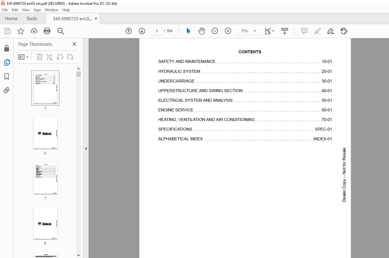
TABLE OF CONTENTS:
Bobcat E45 Compact Excavator Service Manual SN B2VY11001 & Above – PDF DOWNLOAD
MAINTENANCE SAFETY 3
CONTENTS 5
FOREWORD 7
FOREWORD 9
SAFETY INSTRUCTIONS 11
FIRE PREVENTION 13
Maintenance 13
Operation 13
Electrical 13
Hydraulic System 13
Fueling 13
Starting 13
Spark Arrester Exhaust System 13
Welding And Grinding 14
Fire Extinguishers 14
SERIAL NUMBER LOCATIONS 15
Excavator Serial Number 15
Engine Serial Number 15
DELIVERY REPORT 16
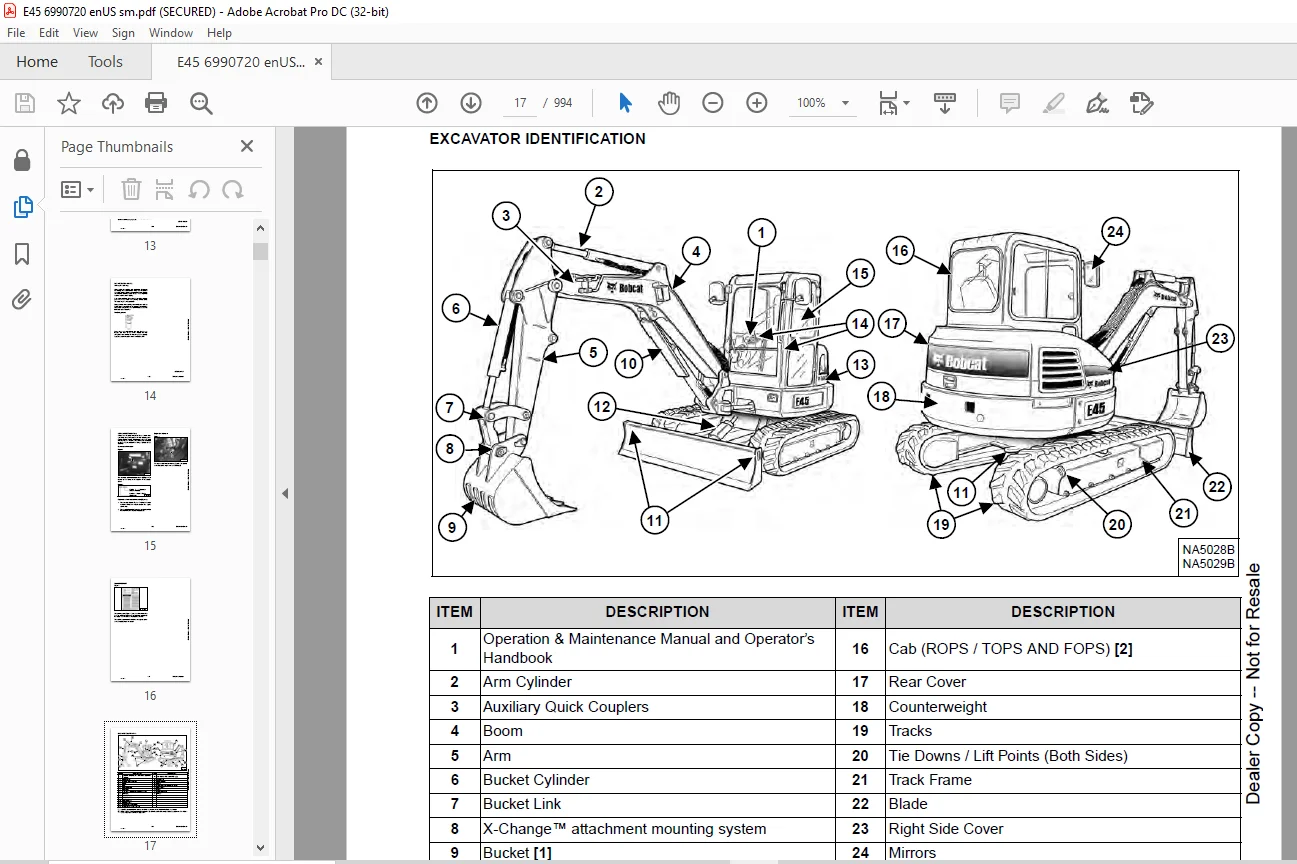
EXCAVATOR IDENTIFICATION 17
SAFETY AND MAINTENANCE 19
LIFTING AND BLOCKING THE EXCAVATOR 23
Procedure 23
LIFTING THE EXCAVATOR 25
Procedure 25
OPERATOR CAB (ROPS / TOPS) 27
Description 27
Cab Door 28
Front Window 29
Front Wiper 30
Window Washer Reservoir 30
Right Side Windows 31
OPERATOR CANOPY (ROPS / TOPS) 33
Description 33
TRANSPORTING THE EXCAVATOR ON A TRAILER 35
Loading And Unloading 35
Fastening 36
TAILGATE 37
Opening And Closing 37
Adjusting The Latch 37
RIGHT SIDE COVER 39
Opening And Closing 39
SERVICE SCHEDULE 41
Maintenance Intervals 41
AIR CLEANER SERVICE 43
Replacing The Filter Elements 43
CAB FILTERS 45
Cleaning And Maintenance 45
ENGINE COOLING SYSTEM 47
Cleaning 47
Checking Level 48
Removing And Replacing Coolant 49
FUEL SYSTEM 51
Fuel Specifications 51
Biodiesel Blend Fuel 51
Filling The Fuel Tank 52
Fuel Filters 53
Removing Air From The Fuel System 54
Draining The Fuel Tank 54
ENGINE LUBRICATION SYSTEM 55
Checking And Adding Engine Oil 55
Engine Oil Chart 55
Removing And Replacing Oil And Filter 56
HYDRAULIC SYSTEM 57
Checking And Adding Hydraulic Oil 57
Hydraulic / Hydrostatic Fluid Chart 58
Removing And Replacing The Hydraulic Filters 59
Removing And Replacing The Hydraulic Fluid 61
LUBRICATING THE EXCAVATOR 63
Lubrication Locations 63
PIVOT PINS 67
Inspection And Maintenance 67
TRAVEL MOTOR 69
Checking And Adding Oil 69
Removing And Replacing Oil 69
EMERGENCY EXIT 71
Right Side Rear Window 71
Front Window 71
SEAT BELT 73
Inspection And Maintenance 73
CONTROL CONSOLE LOCKOUTS 75
Inspection And Maintenance 75
TOWING THE EXCAVATOR 77
Procedure 77
REMOTE START TOOL KIT – MEL1563 79
Remote Start Tool Kit – MEL1563 79
Service Tool Harness Control – MEL1565 80
Service Tool Harness Communicator – MEL1566 81
REMOTE START TOOL (SERVICE TOOL) KIT – 7217666 83
Description 83
Remote Start Tool (Service Tool) – 7022042 84
Excavator Service Tool Harness – 6689747 85
Computer Service Tool Harness – 6689746 86
HYDRAULIC SYSTEM 87
HYDRAULIC / HYDROSTATIC SCHEMATICS 93
HYDRAULIC SYSTEM INFORMATION 95
Glossary Of Hydraulic / Hydrostatic Symbols 95
Troubleshooting The Hydraulic Circuit 98
Troubleshooting The Cylinder Circuit 99
Troubleshooting The Swing (Upperstructure Slew) Circuit 100
Troubleshooting The Travel Circuit 101
CYLINDER (BOOM) 103
Testing 103
Removal And Installation 105
Parts Identification 108
Disassembly 109
Assembly 112
CYLINDER (ARM) 117
Testing 117
Removal And Installation 119
Parts Identification 121
Disassembly 122
Assembly 124
CYLINDER (BOOM SWING) 129
Testing 129
Removal And Installation 131
Parts Identification 134
Disassembly 135
Assembly 137
CYLINDER (BUCKET) 141
Testing 141
Removal And Installation 143
Parts Identification 145
Disassembly 146
Assembly 148
CYLINDER (BLADE) 151
Testing 151
Removal And Installation 153
Parts Identification 154
Disassembly 155
Assembly 157
CYLINDER (CLAMP) 161
Testing 161
Removal And Installation 162
Parts Identification 164
Disassembly 165
Assembly 168
CYLINDER (ANGLE BLADE) 173
Testing 173
Removal And Installation 175
Parts Identification 177
Disassembly 178
Assembly 180
CYLINDER (EXTENDABLE ARM) 183
Testing 183
Parts Identification 185
Disassembly 186
Assembly 189
VALVES (MAIN RELIEF) 193
Testing And Adjusting 193
VALVES (PORT RELIEF) 195
Testing And Adjusting 195
VALVES (CROSS PORT RELIEF) 197
Testing And Adjusting 197
Removal And Installation 200
VALVES (PRESSURE REDUCING) 201
Testing And Adjusting 201
HYDRAULIC CONTROL VALVE 203
Description 203
Removal And Installation 203
Parts Identification 207
Disassembly And Assembly 208
Inlet Valve Section Disassembly And Assembly 212
Boom Swing Valve Section Disassembly And Assembly 216
Slew Valve Section Disassembly And Assembly 219
Blade Valve Section Disassembly And Assembly 223
Right And Left Travel Valve Section Disassembly And Assembly 227
Angle Blade, Boom, Auxiliary, Arm And Bucket Valve Section Disassembly And Assembly 229
HYDRAULIC PUMP 233
Hydraulic Pump Work Sheet 233
Pump Testing 236
Removal And Installation 245
Coupler Removal And Installation 246
Hydraulic Pump Startup 247
Torque Limiter Assembly Parts Identification 248
Torque Limiter Assembly Removal And Installation 249
Torque Limiter Valve Assembly Disassembly And Assembly 249
Pump Control Parts Identification 250
Pump Control Removal And Installation 251
Pump Control Disassembly And Assembly 251
Parts Identification 257
Disassembly And Assembly 258
MANIFOLD ASSEMBLY / ACCUMULATOR (WITHOUT ANGLE BLADE) 267
Description 267
Removal And Installation 267
Parts Identification 269
Disassembly And Assembly 270
MANIFOLD ASSEMBLY / ACCUMULATOR (WITH ANGLE BLADE) 277
Description 277
Removal And Installation 277
Parts Identification 279
Disassembly And Assembly 280
TRAVEL MOTOR 287
Removal And Installation 287
Parts Identification Hydraulic Motor 288
Parts Identification Gear Reduction Hub 289
Disassembly 290
Assembly 300
TRAVEL MOTOR (S/N B3VY16000 & Above) 313
Removal And Installation 313
Parts Identification Hydraulic Motor 314
Parts Identification Gear Reduction Hub 315
Disassembly 316
Assembly 324
SWIVEL JOINT 333
Removal And Installation 333
Parts Identification Angle Blade Swivel (B2VY11001 – B2VY12182) 335
Parts Identification Angle Blade Swivel (B2VY12183 – B2VY13176) 336
Parts Identification Angle Blade Swivel (B2VY13177 & Above) 337
Parts Identification Straight Blade Swivel (B2VY11001 – B2VY12164) 338
Parts Identification Straight Blade Swivel (B2VY12165 – B2VY13175) 339
Parts Identification Straight Blade Swivel (B2VY13176 & Above) 340
Disassembly And Assembly 341
SWING MOTOR 343
Removal And Installation 343
Parts Identification 345
Disassembly And Assembly 346
SWING MOTOR (DRIVE CARRIER) 355
Removal And Installation 355
Parts Identification 356
Disassembly And Assembly 357
CONTROL PATTERN SELECTOR VALVE 363
Removal And Installation 363
Parts Identification 364
Disassembly And Assembly 365
RIGHT CONTROL LEVER (JOYSTICK) 367
Testing 367
Handle Removal And Installation 368
Joystick Assembly Removal And Installation 370
Parts Identification 371
Disassembly 372
Assembly 376
LEFT CONTROL LEVER (JOYSTICK) 381
Testing 381
Handle Removal And Installation 382
Joystick Assembly Removal And Installation 384
Parts Identification 385
Disassembly 386
Assembly 390
HYDRAULIC FILTER MOUNT 395
Removal And Installation 395
HYDRAULIC RESERVOIR 397
Removal And Installation 397
OIL COOLER 399
Removal And Installation 399
DIRECT TO TANK VALVE 401
Removal And Installation 401
BLADE CONTROL LEVER 403
Handle Removal And Installation 403
Removal And Installation 405
Parts Identification 407
Disassembly And Assembly 408
CASE DRAIN FILTER MOUNT 413
Removal And Installation 413
TRAVEL CONTROL VALVE 415
Removal And Installation 415
Parts Identification 416
Disassembly And Assembly 417
REMOVING AIR FROM THE HYDRAULIC SYSTEM 423
Procedure 423
MANIFOLD (HYDRAULIC X-CHANGE) (EARLIER MODELS) 425
Removal And Installation 425
Parts Identification 426
Disassembly And Assembly 427
MANIFOLD (HYDRAULIC X-CHANGE) (LATER MODELS) 431
Removal And Installation 431
Parts Identification 432
Disassembly And Assembly 433
MANIFOLD (PIN GRABBER) 439
Removal And Installation 439
Parts Identification 440
Disassembly And Assembly 441
SECONDARY AUXILIARY VALVE (EARLIER MODELS) 443
Removal And Installation 443
Parts Identification 445
Disassembly And Assembly 446
SECONDARY AUXILIARY VALVE (LATER MODELS) 451
Removal And Installation 451
Parts Identification 453
Disassembly And Assembly 454
VALVE (BOOM LOCK) 457
Removal And Installation 457
VALVE (ARM LOCK) 459
Removal And Installation 459
UNDERCARRIAGE 461
BLADE 463
Removal And Installation 463
BLADE (ANGLE) 465
Removal And Installation 465
Cutting Edge Removal And Installation 466
TRACK UNDERCARRIAGE COMPONENTS (RUBBER TRACK) 467
Description 467
Track Lug Height 467
Checking Tension 468
Adjusting Tension 469
Track Removal And Installation 471
Idler Removal And Installation 472
Idler Parts Identification 473
Idler Disassembly 474
Idler Assembly 476
Track Tensioner Removal And Installation 479
Track Tensioner Parts Identification 480
Track Tensioner Disassembly And Assembly 481
Roller Removal And Installation 483
Sprocket Removal And Installation 484
TRACK UNDERCARRIAGE COMPONENTS (STEEL TRACK) 485
Description 485
Checking Tension 486
Adjusting Tension 487
Track Removal 489
Track Installation 492
Idler Removal And Installation 494
Idler Parts Identification 495
Idler Disassembly 496
Idler Assembly 498
Track Tensioner Removal And Installation 501
Track Tensioner Parts Identification 502
Track Tensioner Disassembly And Assembly 503
Roller Removal And Installation 505
Sprocket Removal And Installation 506
Guide Plate Removal And Installation 506
TRACK MAINTENANCE 507
Track Damage Identification 507
SWING CIRCLE GEAR 519
Swing Bearing Removal 519
Swing Bearing Installation 520
UPPERSTRUCTURE AND SWING SECTION 521
UPPERSTRUCTURE 525
Removal 525
Installation 527
ROPS CANOPY 529
Removal And Installation 529
CAB 533
Removal And Installation 533
Door Removal And Installation 536
Front Window Removal And Installation 537
Front Window Disassembly And Assembly 538
Front Window Adjustment 540
Right Side Rear Sliding Window Removal And Installation 542
Right Side Front Sliding Window Removal And Installation 542
Right Side Front And Rear Sliding Window Weather Strip Removal And Installation 543
Right Side Front And Rear Sliding Window Wiper Strip Removal And Installation 543
Glass Removal 544
Glass Installation 545
SEAT 553
Removal And Installation 553
Seat Mount Removal And Installation 554
RIGHT CONSOLE 555
Console Cover Removal And Installation 555
LEFT CONSOLE 561
Lower Console Cover Removal And Installation 561
Upper Console Cover Removal And Installation 562
Compression Spring Removal And Installation 565
Lock Lever Removal And Installation 567
Console Removal And Installation 567
LEFT UPPERSTRUCTURE COVER 569
Removal And Installation 569
RIGHT UPPERSTRUCTURE COVER 571
Removal And Installation 571
COUNTERWEIGHT 573
Removal And Installation 573
Long Arm Counterweight Removal And Installation 576
TRAVEL LEVERS AND PEDALS 577
Removal And Installation 577
Disassembly And Assembly 578
FLOOR MAT 579
Removal And Installation 579
FUEL TANK 581
Removal And Installation (Canopy Equipped Excavator) 581
Removal And Installation (Cab Equipped Excavator) 582
Fuel Tank Fitting Removal And Installation 582
HORN 583
Removal And Installation 583
SWING FRAME 585
Removal And Installation 585
Boom Swing Frame Hose Routing 588
Bushing Removal 589
Bushing Installation 590
BOOM 591
Removal And Installation 591
STANDARD AND LONG ARM 593
Removal And Installation 593
Arm To Boom Bushing Removal And Installation 594
Arm To Bucket And Bucket Link Bushing Removal And Installation 595
ARM (EXTENDABLE) 597
Removal And Installation 597
Arm To Boom Bushing Removal And Installation 598
Arm To Bucket Bushing Removal And Installation 599
Disassembly And Assembly 600
Shimming Procedure 607
BUCKET 609
Bucket Teeth Removal And Installation 609
Bucket Side Cutting Edge Removal And Installation 610
CLAMP 611
Removal And Installation 611
TAILGATE 613
Removal And Installation 613
Latch Removal And Installation 614
X-CHANGE 615
Removal And Installation 615
Disassembly 617
Assembly 618
X-CHANGE (HYDRAULIC) (EARLIER MODELS) 621
Removal And Installation 621
Parts Identification 623
Disassembly 624
Assembly 629
Expansion Plug Installation 637
X-CHANGE (HYDRAULIC) (LATER MODELS) 639
Removal And Installation 639
Parts Identification 641
Disassembly 642
Assembly 648
Expansion Plug Installation 656
QUICK COUPLER (KLAC™ SYSTEM) 657
Troubleshooting 657
Daily Inspection 657
Removal And Installation 658
Parts Identification 660
Disassembly 661
Assembly 662
QUICK COUPLER (LEHNHOFF® SYSTEM) 665
Troubleshooting 665
Daily Inspection 665
Removal (MS03 And MS08) 666
Installation (MS03 And MS08) 667
Parts Identification (MS03) 668
Disassembly And Assembly (MS03) 669
Parts Identification (MS08) 670
Disassembly (MS08) 671
Assembly (MS08) 674
QUICK COUPLER (PIN GRABBER) 679
Troubleshooting 679
Daily Inspection 680
Removal And Installation 680
Parts Identification 682
Disassembly And Assembly 683
RIGHT SIDE COVER (EARLIER MODELS) 685
Removal And Installation 685
Latch Removal And Installation 686
Latch Adjustment 687
RIGHT SIDE COVER (LATER MODELS) 689
Removal And Installation 689
Latch Removal And Installation 690
Adjustment 690
TOOL BOX 693
Removal And Installation 693
ELECTRICAL SYSTEM AND ANALYSIS 695
ELECTRICAL SCHEMATICS 699
ELECTRICAL SYSTEM INFORMATION 707
Troubleshooting Chart 707
Description 708
Fuse And Relay Location / Identification 708
Shut-Off Switch 710
BATTERY 711
Servicing 711
Maintaining Battery Charge Level 711
Battery Service During Machine Storage 711
Battery Testing 712
Battery Charging 712
Removing And Installing 713
Using A Booster Battery (Jump Starting) 714
ALTERNATOR 715
Belt Adjustment 715
Belt Replacement 715
Charging System Inspection 716
Alternator Voltage Testing 717
Low Voltage Testing 717
High Voltage Testing 718
Removal And Installation 719
Parts Identification 720
STARTER 721
Testing 721
Removal And Installation 722
Parts Identification 723
LIGHTS 725
Removal And Installation 725
Boom Light Removal And Installation 726
Boom Light Bulb Replacement 726
MAGNETIC LOCKOUT SENSOR 727
Removal And Installation 727
FUEL LEVEL SENDER 729
Removal And Installation 729
Testing 730
DIAGNOSTIC SERVICE CODES 731
Viewing Service Codes 731
Service Codes List 732
CONTROL PANEL SETUP 737
Panel Setup (Deluxe Instrument Panel) 737
Password Setup (Keyless Start Panel) 743
Password Setup (Deluxe Instrument Panel) 744
Maintenance Clock 746
INSTRUMENT PANEL 749
Removal And Installation 749
CONTROLLER (GATEWAY AND AUXILIARY) 751
Description 751
Gateway Controller Removal and Installation 751
Auxiliary Controller Removal And Installation 753
ENGINE CONTROL UNIT (ECU) 755
Description 755
Cleaning 756
Removal And Installation 757
KEY SWITCH 759
Removal And Installation 759
WIPER MOTOR 761
Removal And Installation 761
MOTION ALARM SYSTEM 763
Description 763
Inspecting 763
Adjusting Switch Position 764
SERVICE PC (LAPTOP COMPUTER) 765
Connecting Remote Start Tool 765
Connecting Remote Start Tool (Service Tool) 765
SHUT-OFF SWITCH 767
Description 767
Removal And Installation 768
TRAVEL MOTOR AUTO-SHIFT 771
Auto-Shift Drive System (If Equipped) 771
Troubleshooting 772
AUTO IDLE PRESSURE SENSOR 775
Description 775
Removal And Installation 776
BOBCAT MACHINE IQ WIRELESS COMMUNICATIONS 777
Description 777
Controller Removal And Installation 777
Antenna Removal And Installation 779
Procedure 781
ENGINE SERVICE 783
ENGINE INFORMATION 787
Description 787
Specifications 788
Sensor Location 790
Torque Values 796
Troubleshooting 798
Engine Removal And Installation 800
Compression – Testing (Using Glow Plug Compression Adapter) 808
Compression – Testing (Using Injector Compression Adapter) 810
Injector Signal – Testing 812
Injector Signal – Testing (In-Line) 814
DIESEL OXIDATION CATALYST (DOC) 817
Removal And Installation 817
AIR CLEANER 819
Housing Removal And Installation 819
ENGINE COOLING SYSTEM 821
Radiator Removal And Installation 821
Fan Removal And Installation 825
Water Pump Removal And Installation 826
Thermostat Housing Removal And Installation 827
Testing The Thermostat 828
LUBRICATION SYSTEM 829
Description 829
Oil Pan Removal And Installation 830
Oil Pump Removal And Installation 831
Oil Pump Relief Valve Description 832
Oil Pump Relief Valve Removal And Installation 832
Oil Cooler Removal And Installation 833
Oil Filter Head Removal And Installation 834
Oil Cooler Bypass Description 835
Oil Cooler Bypass Removal And Installation 835
FUEL SYSTEM 837
Description 837
Transfer Pump / High Pressure Pump Removal And Installation 838
Fuel Temperature Sensor Removal And Installation 841
Fuel Cooler Removal And Installation 842
Fuel Bypass Valve Removal And Installation 843
Fuel Recirculation Valve Removal and Installation 844
Fuel Injector Removal And Installation 845
Removing Air From The Fuel System 847
CYLINDER HEAD 849
Glow Plugs Testing 849
Glow Plug Removal And Installation 850
Valve Clearance Adjustment 851
Cylinder Head Removal And Installation 853
Cylinder Head Disassembly And Assembly 857
Cylinder Head Inspection 858
Cylinder Head Top Clearance 859
Valve Step Height 860
Valve Stem Height 860
Valve Guide 861
Valve 861
Valve Spring 862
Rocker Arm Shaft Disassembly And Assembly 863
Rocker Arm Shaft Inspection 864
Push Rod Inspection 864
CRANKSHAFT AND PISTONS 865
Piston And Connecting Rod Removal And Installation 865
Piston And Connecting Rod Inspection 866
Crankshaft Removal And Installation 868
Cylinder Block Inspection 871
Crankshaft Inspection 873
Connecting Rod Inspection 873
Engine Component Class 874
CAMSHAFT 877
Removal And Installation 877
Inspecting 878
GEARCASE 881
Gearcase Cover Removal And Installation 881
Gear Backlash 882
Gear Timing 883
Idle Gear Removal And Installation 884
Idle Gear Inspection 884
TURBOCHARGER 885
Description 885
Removal And Installation 885
Inspection 888
FLYWHEEL AND HOUSING 889
Hydraulic Pump Coupler Removal And Installation 889
Flywheel Removal And Installation 891
Ring Gear Removal And Installation 891
EXHAUST GAS RECIRCULATION (EGR) SYSTEM 893
Removal And Installation 893
INTERCOOLER 897
Description 897
Removal And Installation 897
HEATING, VENTILATION AND AIR CONDITIONING 899
AIR CONDITIONING SYSTEM FLOW 901
Description 901
Chart 902
Components 903
Safety Equipment 906
REGULAR MAINTENANCE 907
Cab Filters 907
Air Conditioning Compressor Belt Adjustment 909
Air Conditioning Compressor Belt Replacement 909
Condenser 910
Air Conditioning Lubrication 910
Evaporator / Heater Coil 910
Air Conditioning Service Chart 912
TROUBLESHOOTING 913
Blower Motor Does Not Operate 913
Blower Motor Operates Normally, But Air Flow Is Insufficient 913
Insufficient Cooling Although Air Flow And Compressor Operation Are Normal 913
The Compressor Operates Improperly Or Not At All 913
Gauge Pressure Related Troubleshooting 914
Temperature / Pressure Chart 915
Poor A/C Performance 916
HVAC Repair And Leaks 916
Electrical System 917
Engine Coolant Bypassing The Heater Valve 919
SYSTEM CHARGING AND RECLAMATION 921
Refrigerant Identification 921
Reclamation And Charging With Recovery / Charging Unit 923
COMPRESSOR 925
Removal And Installation 925
Oil 926
Oil Check 927
CONDENSER 929
Removal And Installation 929
RECEIVER / DRIER 931
Receiver / Drier Removal And Installation 931
Pressure Switch Removal And Installation 932
EVAPORATOR / HEATER UNIT 933
Removal And Installation 933
THERMOSTAT 935
Description 935
Removal And Installation 936
EXPANSION VALVE 939
Removal And Installation 939
EVAPORATOR COIL 941
Removal And Installation 941
HEATER COIL 943
Removal And Installation 943
BLOWER FAN 945
Removal And Installation 945
HEATER VALVE 947
Removal And Installation 947
HVAC DUCT 949
Removal And Installation 949
SPECIFICATIONS 951
EXCAVATOR SPECIFICATIONS 953
Machine Dimensions 953
Machine Dimensions (Standard Arm) 954
Machine Dimensions (Long Arm) 955
Machine Dimensions (Extendable Arm) 956
Machine Dimensions (Angle Blade) 957
Performance 958
Controls 958
Engine 959
Hydraulic System 960
Hydraulic Cylinders 961
Hydraulic Cycle Times 961
Electrical 962
Drive System 962
Slew System 962
Undercarriage 962
Capacities 962
Tracks 963
Ground Pressure 963
TECHNICAL SERVICE GUIDE SPECIFICATIONS 965
Engine 965
Engine Torques 965
Cooling System 965
Excavator Torques 965
TORQUE SPECIFICATION FOR BOLTS 967
Torque For General SAE Bolts 967
Torque For General Metric Bolts 968
HYDRAULIC CONNECTION SPECIFICATIONS 969
O-ring Face Seal Connection 969
Straight Thread O-ring Fitting 969
Tubelines And Hoses 970
Flare Fitting 970
O-ring Flare Fitting 971
Port Seal Fitting 973
Push To Connect Fittings 974
HYDRAULIC FLUID SPECIFICATIONS 977
Specifications 977
CONVERSIONS 979
Decimal And Millimeter Equivalent Chart 979
U S To Metric Conversion Chart 980
SERVICE TOOLS REQUIRED 981
Remote Start Tools 981
Hydraulic Tools 982
Engine Tools 985
Electrical Tools 987
General Tools 987
HVAC Tools 988
ALPHABETICAL INDEX 989
Contact us: [email protected]
https://vimeo.com/841814656?share=copy
PLEASE NOTE:
- This is the same manual used by the DEALERSHIPS to SERVICE your vehicle.
- The manual can be all yours – Once payment is complete, you will be taken to the download page from where you can download the manual. All in 2-5 minutes time!!
- Need any other service / repair / parts manual, please feel free to contact us at heydownloadss @gmail.com . We may surprise you with a nice offer
S.M