Bobcat E50 Compact Excavator Service Manual 6989441 (01-20) – PDF DOWNLOAD
$35.95
Bobcat E50 Compact Excavator Service Manual 6989441 (01-20) – PDF DOWNLOAD
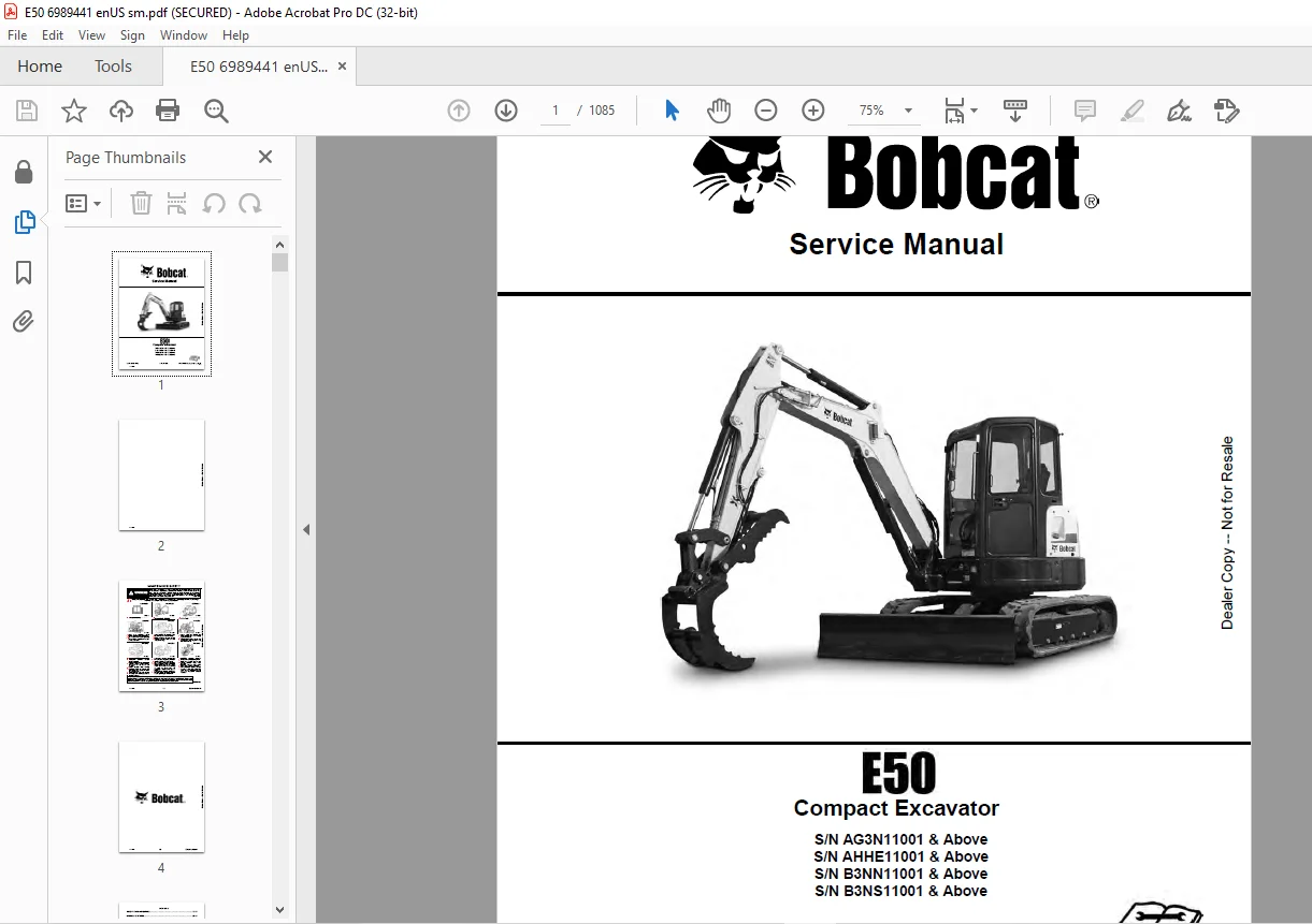
S/N AG3N11001 & Above
S/N AHHE11001 & Above
S/N B3NN11001 & Above
S/N B3NS11001 & Above
Description
Bobcat E50 Compact Excavator Service Manual 6989441 (01-20) – PDF DOWNLOAD
FILE DETAILS:
Bobcat E50 Compact Excavator Service Manual 6989441 (01-20) – PDF DOWNLOAD
Language : English
Pages :1085
Downloadable : Yes
File Type : PDF
DESCRIPTION:
Bobcat E50 Compact Excavator Service Manual 6989441 (01-20) – PDF DOWNLOAD
S/N AG3N11001 & Above
S/N AHHE11001 & Above
S/N B3NN11001 & Above
S/N B3NS11001 & Above
FOREWORD
This manual is for the Bobcat excavator mechanic. It provides necessary servicing and adjustment procedures for the Bobcat excavator and its component parts and systems. Refer to the Operation & Maintenance Manual for operating instructions, starting procedure, daily checks, etc.
SAFETY INSTRUCTIONS
Instructions are necessary before operating or servicing machine. Read and understand the Operation & Maintenance Manual, Operator’s Handbook and signs (decals) on machine. Follow warnings and instructions in the manuals when making repairs, adjustments or servicing. Check for correct function after adjustments, repairs or service. Untrained operators and failure to follow instructions can cause injury or death.
The following publications provide information on the safe use and maintenance of the Bobcat machine and attachments:
- The Delivery Report is used to assure that complete instructions have been given to the new owner and that the machine is in safe operating condition.
- The Operation & Maintenance Manual delivered with the machine or attachment contains operating information as well as routine maintenance and service procedures. It is a part of the machine and can be stored in a container provided on the machine. Replacement Operation & Maintenance Manuals can be ordered from your Bobcat dealer.
- Machine signs (decals) instruct on the safe operation and care of your Bobcat machine or attachment. The signs and their locations are shown in the Operation & Maintenance Manual. Replacement signs are available from your Bobcat dealer.
- An Operator’s Handbook fastened to the operator cab. It’s brief instructions are convenient to the operator. The handbook is available from your dealer in an English edition or one of many other languages. See your Bobcat dealer for more information on translated versions.
- The AEM Safety Manual delivered with the machine gives general safety information.
- The Service Manual and Parts Manual are available from your dealer for use by mechanics to do shoptype service and repair work.
IMAGES PREVIEW OF THE MANUAL:
TABLE OF CONTENTS:
Bobcat E50 Compact Excavator Service Manual 6989441 (01-20) – PDF DOWNLOAD
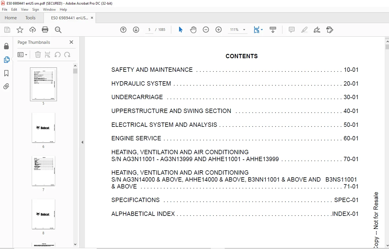
MAINTENANCE SAFETY 3
CONTENTS 5
FOREWORD 7
FOREWORD 9
SAFETY INSTRUCTIONS 11
FIRE PREVENTION 13
Maintenance 13
Operation 13
Electrical 13
Hydraulic System 13
Fueling 13
Starting 13
Spark Arrester Exhaust System 13
Welding And Grinding 14
Fire Extinguishers 14
SERIAL NUMBER LOCATIONS 15
Excavator Serial Number 15
Engine Serial Number 15
DELIVERY REPORT 16
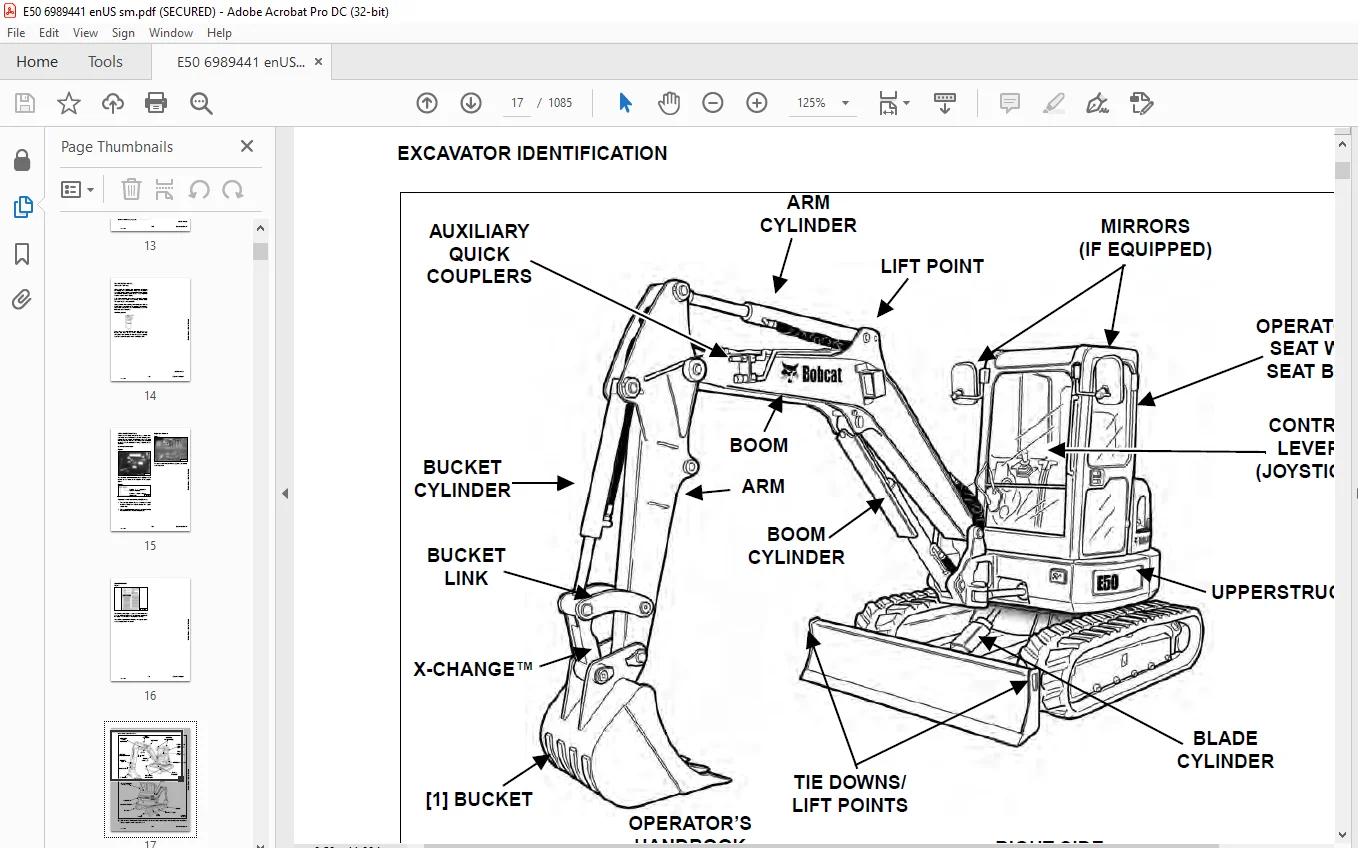
EXCAVATOR IDENTIFICATION 17
SAFETY AND MAINTENANCE 19
LIFTING AND BLOCKING THE EXCAVATOR 23
Procedure 23
LIFTING THE EXCAVATOR 25
Procedure 25
OPERATOR CAB (ROPS / TOPS) 27
Description 27
Cab Door 28
Front Window 29
Front Wiper 30
Window Washer Reservoir 30
Right Side Windows 31
OPERATOR CANOPY (ROPS / TOPS) 33
Description 33
TRANSPORTING THE EXCAVATOR ON A TRAILER 35
Loading And Unloading 35
Fastening 35
TAILGATE 37
Opening And Closing 37
Adjusting The Latch 37
RIGHT SIDE COVER 39
Opening And Closing 39
SERVICE SCHEDULE 41
Maintenance Intervals 41
AIR CLEANER SERVICE 43
Daily Check 43
Replacing The Filter Elements 43
CAB FILTERS (S/N AG3N11001 – AG3N13999 AND AHHE11001 – AHHE13999) 45
Cleaning And Maintenance 45
CAB FILTERS (S/N AG3N14000 & ABOVE, AHHE14000 & ABOVE, B3NN11001 AND B3NS11001 & ABOVE) 47
Cleaning And Maintenance 47
ENGINE COOLING SYSTEM 49
Cleaning 49
Checking Level 50
Removing And Replacing Coolant 51
FUEL SYSTEM 53
Fuel Specifications 53
Biodiesel Blend Fuel 53
Filling The Fuel Tank 54
Fuel Filters 55
Draining The Fuel Tank 55
Removing Air From The Fuel System 56
ENGINE LUBRICATION SYSTEM 57
Checking And Adding Engine Oil 57
Engine Oil Chart 57
Removing And Replacing Oil And Filter 58
HYDRAULIC SYSTEM 59
Checking And Adding Hydraulic Fluid 59
Hydraulic / Hydrostatic Fluid Chart 60
Removing And Replacing The Hydraulic Filters 60
Removing And Replacing The Hydraulic Fluid 62
LUBRICATING THE EXCAVATOR (EARLIER MODELS) 65
Lubrication Locations 65
LUBRICATING THE EXCAVATOR (LATER MODELS) 69
Lubrication Locations 69
PIVOT PINS 73
Inspection And Maintenance 73
TRAVEL MOTOR 75
Checking And Adding Oil 75
Removing And Replacing Oil 75
SPARK ARRESTER MUFFLER 77
Cleaning Procedure 77
EMERGENCY EXIT 79
Right Side Rear Window 79
Front Window 79
SEAT BELT 81
Inspection And Maintenance 81
CONTROL CONSOLE LOCKOUTS 83
Inspection And Maintenance 83
TOWING THE EXCAVATOR 85
Procedure 85
REMOTE START TOOL KIT – MEL1563 87
Remote Start Tool – MEL1563 87
Service Tool Harness Control – MEL1565 88
Service Tool Harness Communicator – MEL1566 89
REMOTE START TOOL (SERVICE TOOL) KIT – 7217666 91
Description 91
Remote Start Tool (Service Tool) – 7022042 92
Excavator Service Tool Harness – 6689747 93
Computer Service Tool Harness – 6689746 94
HYDRAULIC SYSTEM 95
HYDRAULIC / HYDROSTATIC SCHEMATICS 101
HYDRAULIC SYSTEM INFORMATION 109
Glossary Of Hydraulic / Hydrostatic Symbols 109
Troubleshooting The Hydraulic Circuit 112
Troubleshooting The Cylinder Circuit 113
Troubleshooting The Swing (Upperstructure Slew) Circuit 114
Troubleshooting The Travel Circuit 115
CYLINDER (BOOM) (S/N AG3N11018 & ABOVE, AHHE11035 & ABOVE, B3NN11001 & ABOVE AND B3NS11001 & ABOVE) 117
Testing 117
Removal And Installation 119
Parts Identification 122
Disassembly 123
Assembly 126
CYLINDER (BOOM) (S/N AG3N11017 & BELOW, AHHE11034 & BELOW) 131
Testing 131
Removal And Installation 133
Parts Identification 136
Disassembly 137
Assembly 140
CYLINDER (ARM) 145
Testing 145
Removal And Installation 147
Parts Identification 149
Disassembly 150
Assembly 152
CYLINDER (BOOM SWING) 157
Testing 157
Removal And Installation 159
Parts Identification 162
Disassembly 163
Assembly 165
CYLINDER (BUCKET) 169
Testing 169
Removal And Installation 171
Parts Identification 173
Disassembly 174
Assembly 176
CYLINDER (BLADE) 179
Testing 179
Removal And Installation 181
Parts Identification 182
Disassembly 183
Assembly 185
CYLINDER (CLAMP) 189
Testing 189
Removal And Installation 190
Parts Identification 192
Disassembly 193
Assembly 196
CYLINDER (ANGLE BLADE) 201
Testing 201
Removal And Installation 202
Parts Identification 204
Disassembly 205
Assembly 207
VALVES (MAIN RELIEF) 211
Testing And Adjusting 211
VALVES (PORT RELIEF) 213
Testing And Adjusting Port Relief Valve Pressure 213
VALVES (CROSS PORT RELIEF) 215
Testing And Adjusting 215
Removal And Installation 218
VALVES (PRESSURE REDUCING) 219
Testing And Adjusting 219
HYDRAULIC CONTROL VALVE 221
Description 221
Removal And Installation 221
Parts Identification 225
Disassembly And Assembly 226
Inlet Valve Section Disassembly And Assembly 230
Boom Swing Valve Section Disassembly And Assembly 234
Slew Valve Section Disassembly And Assembly 237
Blade Valve Section Disassembly And Assembly 240
Right And Left Travel Valve Section Disassembly And Assembly 244
Angle Blade, Boom, Auxiliary, Arm And Bucket Valve Section Disassembly And Assembly 246
HYDRAULIC PUMP 251
Hydraulic Pump Work Sheet 251
Pump Testing 254
Removal And Installation 263
Coupler Removal And Installation 264
Hydraulic Pump Startup 265
Torque Limiter Assembly Parts Identification 266
Torque Limiter Assembly Removal And Installation 267
Torque Limiter Valve Assembly Disassembly And Assembly 267
Pump Control Parts Identification 268
Pump Control Removal And Installation 269
Pump Control Disassembly And Assembly 269
Parts Identification 275
Disassembly And Assembly 276
MANIFOLD ASSEMBLY / ACCUMULATOR (WITHOUT ANGLE BLADE) 285
Description 285
Removal And Installation 286
Parts Identification 288
Disassembly And Assembly 289
MANIFOLD ASSEMBLY / ACCUMULATOR (WITH ANGLE BLADE) 295
Description 295
Removal And Installation 295
Parts Identification 297
Disassembly And Assembly 298
TRAVEL MOTOR 305
Removal And Installation 305
Parts Identification Hydraulic Motor 306
Parts Identification Gear Reduction Hub 307
Disassembly 308
Assembly 317
TRAVEL MOTOR (S/N AG3N17000 & ABOVE) 329
Removal And Installation 329
Parts Identification Hydraulic Motor 330
Parts Identification Gear Reduction Hub 331
Disassembly 332
Assembly 340
SWIVEL JOINT 349
Removal And Installation 349
Parts Identification Angle Blade Swivel (S/N AG3N11001 – AG3N14896, AHHE11001 – AHHE15388) 351
Parts Identification Angle Blade Swivel (S/N AG3N14897 – AG3N15027, AHHE15389 & Above) 352
Parts Identification Angle Blade Swivel (S/N AG3N15028 & Above) 353
Parts Identification Straight Blade Swivel (S/N AG3N11001 – AG3N14896, AHHE11001 – AHHE15371) 354
Parts Identification Straight Blade Swivel (S/N AG3N14897 – AG3N15167, AHHE15372 & Above) 355
Parts Identification Straight Blade Swivel (S/N AG3N15168 & Above) 356
Disassembly And Assembly 357
SWING MOTOR 359
Removal And Installation 359
Parts Identification 361
Disassembly And Assembly 362
SWING MOTOR (DRIVE CARRIER) 371
Removal And Installation 371
Parts Identification 372
Disassembly And Assembly 373
CONTROL PATTERN SELECTOR VALVE 379
Removal And Installation 379
Parts Identification 380
Disassembly And Assembly 381
RIGHT CONTROL LEVER (JOYSTICK) (S/N AG3N11001 – AG3N13999 AND AHHE11001 – AHHE13999) 383
Testing 383
Handle Removal And Installation 384
Joystick Assembly Removal And Installation 386
Parts Identification 387
Disassembly 388
Assembly 393
RIGHT CONTROL LEVER (JOYSTICK) (S/N AG3N14001 & ABOVE, AHHE14001 & ABOVE, B3NN11001 & ABOVE, AND B3NS11001 & ABOVE) 397
Testing 397
Handle Removal And Installation 398
Joystick Assembly Removal And Installation 400
Parts Identification 401
Disassembly 402
Assembly 406
LEFT CONTROL LEVER (JOYSTICK) (S/N AG3N11001 – AG3N13999 AND AHHE11001 – AHHE13999) 411
Testing 411
Handle Removal And Installation 412
Joystick Assembly Removal And Installation 414
Parts Identification 415
Disassembly 416
Assembly 420
LEFT CONTROL LEVER (JOYSTICK) (AG3N14001 & ABOVE, AHHE14001 & ABOVE, B3NN11001 & ABOVE AND B3NS11001 & ABOVE) 425
Testing 425
Handle Removal And Installation 426
Joystick Assembly Removal And Installation 428
Parts Identification 429
Disassembly 430
Assembly 434
HYDRAULIC FILTER MOUNT 439
Removal And Installation 439
HYDRAULIC RESERVOIR 441
Removal And Installation 441
OIL COOLER 443
Removal And Installation 443
DIRECT TO TANK VALVE 445
Removal And Installation 445
BLADE CONTROL LEVER 447
Handle Removal And Installation 447
Removal And Installation 449
Parts Identification 450
Disassembly And Assembly 451
CASE DRAIN FILTER MOUNT 455
Removal And Installation 455
TRAVEL CONTROL VALVE 457
Removal And Installation 457
Parts Identification 458
Disassembly And Assembly 459
REMOVING AIR FROM THE HYDRAULIC SYSTEM 465
Procedure 465
MANIFOLD (HYDRAULIC X-CHANGE) (EARLIER MODELS) 467
Removal And Installation 467
Parts Identification 468
Disassembly And Assembly 469
MANIFOLD (HYDRAULIC X-CHANGE) (LATER MODELS) 473
Removal And Installation 473
Parts Identification 474
Disassembly And Assembly 475
MANIFOLD (PIN GRABBER) 481
Removal And Installation 481
Parts Identification 482
Disassembly And Assembly 483
SECONDARY AUXILIARY VALVE (EARLIER MODELS) 485
Removal And Installation 485
Parts Identification 487
Disassembly And Assembly 488
SECONDARY AUXILIARY VALVE (LATER MODELS) 493
Removal And Installation 493
Parts Identification 495
Disassembly And Assembly 496
VALVE (BOOM LOCK) 499
Removal And Installation 499
VALVE (ARM LOCK) 501
Removal And Installation 501
UNDERCARRIAGE 503
BLADE 505
Removal And Installation 505
BLADE (ANGLE) 507
Removal And Installation 507
Cutting Edge Removal And Installation 508
TRACK UNDERCARRIAGE COMPONENTS (RUBBER TRACK) 509
Description 509
Track Lug Height 509
Checking Tension 510
Adjusting Tension 511
Track Removal And Installation 513
Idler Removal And Installation 514
Idler Parts Identification 515
Idler Disassembly 516
Idler Assembly 518
Track Tensioner Removal And Installation 521
Track Tensioner Parts Identification 522
Track Tensioner Disassembly And Assembly 523
Roller Removal And Installation 525
Sprocket Removal And Installation 526
TRACK UNDERCARRIAGE COMPONENTS (STEEL TRACK) 527
Description 527
Checking Tension 528
Adjusting Tension 529
Track Removal 531
Track Installation 534
Idler Removal And Installation 536
Idler Parts Identification 537
Idler Disassembly 538
Idler Assembly 540
Track Tensioner Removal And Installation 543
Track Tensioner Parts Identification 544
Track Tensioner Disassembly And Assembly 545
Roller Removal And Installation 547
Sprocket Removal And Installation 548
Guide Plate Removal And Installation 548
TRACK MAINTENANCE 549
Track Damage Identification 549
SWING CIRCLE GEAR 561
Swing Bearing Removal 561
Swing Bearing Installation 562
UPPERSTRUCTURE AND SWING SECTION 563
UPPERSTRUCTURE 567
Removal 567
Installation 569
ROPS CANOPY 571
Removal And Installation 571
CAB 575
Removal And Installation 575
Door Removal And Installation 578
Front Window Removal And Installation (Earlier Models) 579
Front Window Removal And Installation (Later Models) 580
Front Window Disassembly And Assembly (Later Models) 581
Front Window Adjustment (Later Models) 583
Right Side Rear Sliding Window Removal And Installation 585
Right Side Front Sliding Window Removal And Installation 585
Right Side Front And Rear Sliding Window Weather Strip Removal And Installation 586
Right Side Front And Rear Sliding Window Wiper Strip Removal And Installation 586
Glass Removal 587
Glass Installation 588
SEAT 595
Removal And Installation 595
Seat Mount Removal And Installation 596
RIGHT CONSOLE (S/N AG3N11001 – AG3N13999 AND AHHE11001 – AHHE13999) 597
Console Cover Removal And Installation 597
RIGHT CONSOLE (S/N AG3N14000 & ABOVE, AHHE14000 & ABOVE, B3NN11001 & ABOVE AND B3NS11001 & ABOVE) 603
Console Cover Removal And Installation 603
LEFT CONSOLE 609
Lower Console Cover Removal And Installation 609
Upper Console Cover Removal And Installation 610
Compression Spring Removal And Installation 613
Lock Lever Removal And Installation 615
Console Removal And Installation 615
LEFT UPPERSTRUCTURE COVER 617
Removal And Installation 617
RIGHT UPPERSTRUCTURE COVER 619
Removal And Installation 619
COUNTERWEIGHT 621
Removal And Installation 621
Long Arm Counterweight Removal And Installation 624
TRAVEL LEVERS AND PEDALS 625
Removal And Installation 625
Disassembly And Assembly 626
FLOOR MAT 627
Removal And Installation 627
FUEL TANK 629
Removal And Installation 629
Fuel Tank Fitting Removal And Installation 630
Removal And Installation (Cab Equipped Excavator) 630
HORN 631
Removal And Installation 631
SWING FRAME 633
Removal And Installation 633
Boom Swing Frame Hose Routing 636
Bushing Removal 637
Bushing Installation 638
BOOM 639
Removal And Installation 639
ARM (STANDARD AND LONG) 641
Removal And Installation 641
Arm To Boom Bushing Removal And Installation 642
Arm To Bucket And Bucket Link Bushing Removal And Installation 643
BUCKET 645
Bucket Teeth Removal And Installation 645
Bucket Side Cutting Edge Removal And Installation 646
CLAMP 647
Removal And Installation 647
TAILGATE 649
Removal And Installation 649
Latch Removal And Installation 650
X-CHANGE 651
Removal And Installation 651
Disassembly 653
Assembly 654
X-CHANGE (HYDRAULIC) (EARLIER MODELS) 657
Removal And Installation 657
Parts Identification 659
Disassembly 660
Assembly 665
Expansion Plug Installation 673
X-CHANGE (HYDRAULIC) (LATER MODELS) 675
Removal And Installation 675
Parts Identification 677
Disassembly 678
Assembly 684
Expansion Plug Installation 692
QUICK COUPLER (KLAC™ SYSTEM) 693
Troubleshooting 693
Daily Inspection 693
Removal And Installation 694
Parts Identification 696
Disassembly 697
Assembly 699
QUICK COUPLER (LEHNHOFF® SYSTEM) 701
Troubleshooting 701
Daily Inspection 701
Removal (MS03 And MS08) 702
Installation (MS03 And MS08) 703
Parts Identification (MS03) 704
Disassembly And Assembly (MS03) 705
Parts Identification (MS08) 706
Disassembly (MS08) 707
Assembly (MS08) 710
QUICK COUPLER (PIN GRABBER) 715
Troubleshooting 715
Daily Inspection 716
Removal And Installation 717
Parts Identification 718
Disassembly And Assembly 719
RIGHT SIDE COVER (EARLIER MODELS) 721
Removal And Installation 721
Latch Removal And Installation 722
Latch Adjustment 723
RIGHT SIDE COVER (LATER MODELS) 725
Removal And Installation 725
Latch Removal And Installation 726
Adjustment 726
TOOL BOX 729
Removal And Installation 729
ELECTRICAL SYSTEM AND ANALYSIS 731
ELECTRICAL SCHEMATICS 735
ELECTRICAL SYSTEM INFORMATION 746
Troubleshooting Chart 746
Description 747
Fuse And Relay Location / Identification 747
Shut-Off Switch (If Equipped) 749
BATTERY 750
Servicing 750
Removing And Installing 751
Using A Booster Battery (Jump Starting) 752
ALTERNATOR 754
Belt Adjustment 754
Belt Replacement 754
Charging System Inspection 756
Alternator Voltage Testing 757
Low Voltage Testing 757
High Voltage Testing 758
Removal And Installation 759
Parts Identification 761
STARTER 762
Testing 762
Removal And Installation 763
Parts Identification 764
LIGHTS 766
Removal And Installation 766
Boom Light Removal And Installation 767
Boom Light Bulb Replacement 767
MAGNETIC LOCKOUT SENSOR 768
Removal And Installation 768
FUEL LEVEL SENDER 770
Removal And Installation 770
Testing 771
DIAGNOSTIC SERVICE CODES (S/N AG3N11001 – AG3N13999 AND AHHE11001 – AHHE13999) 772
Service Codes List 772
DIAGNOSTIC SERVICE CODES (S/N AG3N14000 & ABOVE, AHHE14000 & ABOVE, B3NN11001 & ABOVE AND B3NS11001 & ABOVE) 774
Viewing Service Codes 774
Number Codes List 775
DELUXE INSTRUMENT PANEL SETUP (S/N AG3N11001 – AG3N13999 AND AHHE11001 – AHHE13999) 778
Passwords 778
Password Entry (For Starting And Operating The Machine) 778
Changing The Operator Password 778
Password Lockout Feature 779
Job Clock 779
RPM 779
CONTROL PANEL SETUP (S/N AG3N14000 & ABOVE, AHHE14000 & ABOVE, B3NN11001 & ABOVE AND B3NS11001 & ABOVE) 780
Panel Setup (Deluxe Instrument Panel) 780
Password Setup (Keyless Start Panel) 786
Password Setup (Deluxe Instrument Panel) 787
Maintenance Clock 789
INSTRUMENT PANEL / CONTROLLER (S/N AG3N11001 – AG3N13999 AND AHHE11001 – AHHE13999) 792
Removal And Installation 792
INSTRUMENT PANEL (S/N AG3N14000 & ABOVE, AHHE14000 & ABOVE, B3NN11001 & ABOVE AND B3NS11001 & ABOVE) 794
Removal And Installation 794
CONTROLLER (S/N AG3N14000 & ABOVE, AHHE14000 & ABOVE, B3NN11001 & ABOVE AND B3NS11001 & ABOVE) (GATEWAY AND AUXILIARY) 796
Description 796
Gateway Controller Removal And Installation 796
Auxiliary Controller Removal And Installation 797
KEY SWITCH 798
Removal And Installation 798
WIPER MOTOR 800
Removal And Installation 800
MOTION ALARM SYSTEM 802
Description 802
Inspecting 802
Adjusting Switch Position 803
SERVICE PC (LAPTOP COMPUTER) 804
Connecting The Remote Start Tool 804
Connecting Remote Start Tool (Service Tool) 804
Operation 805
SHUT-OFF SWITCH 806
Description 806
Removal And Installation 807
TRAVEL MOTOR AUTO-SHIFT 810
Auto-Shift Drive System (If Equipped) 810
Troubleshooting 811
AUTO IDLE PRESSURE SENSOR 814
Description 814
Removal And Installation 815
BOBCAT MACHINE IQ WIRELESS COMMUNICATIONS 816
Description 816
Controller Removal And Installation 816
Antenna Removal And Installation 818
Procedure 820
ENGINE SERVICE 822
ENGINE INFORMATION 826
Description 826
Specifications 827
Crankshaft Re-Grind Data 833
Torque For Kubota® Metric Bolts 834
Troubleshooting 835
Removal And Installation 836
Compression Checking 846
ENGINE SPEED CONTROL 848
Removal And Installation 848
Auto Idle Description 848
Auto Idle Controller Removal And Installation 849
Calibration 850
Actuator Removal And Installation (Earlier Model) 853
Actuator Removal And Installation (Later Model) 856
MUFFLER 858
Removal And Installation 858
AIR CLEANER 860
Housing Removal And Installation 860
ENGINE COOLING SYSTEM 862
Radiator Removal And Installation 862
Fan Removal And Installation 866
Water Pump Removal And Installation 868
Water Pump Disassembly And Assembly 868
Thermostat Housing Removal And Installation 869
Thermostat – Checking 869
LUBRICATION SYSTEM 870
Oil Pan Removal And Installation 870
Oil Pump Removal And Installation 870
Oil Pump Inspection 871
Engine Oil Pressure – Testing 872
FUEL SYSTEM 874
Fuel Shutoff Solenoid – Checking 874
Fuel Shut-off Solenoid Removal And Installation 875
Fuel Injection Pump – Checking 876
Fuel Injection Pump Removal And Installation 877
Fuel Injection Pump – Timing 880
Fuel Camshaft Removal And Installation 882
Fuel Camshaft Governor 883
Fuel Injector Removal And Installation 884
Fuel Injector Nozzle Pressure – Checking 886
Nozzle Spray Condition 887
Valve Seat Tightness 887
CYLINDER HEAD 888
Glow Plugs – Testing 888
Glow Plugs Removal And Installation 889
Valve Clearance Adjustment 890
Valve Timing – Checking 890
Cylinder Head Removal And Installation 891
Cylinder Head Disassembly And Assembly 894
Cylinder Head – Servicing 895
Cylinder Head Top Clearance 895
Valve Guide – Checking 896
Valve Guide Removal And Installation 897
Reconditioning The Valve And Valve Seat 898
Valve Spring 899
Valve Tappets 900
Rocker Arm And Shaft – Checking 901
Push Rod Alignment – Checking 901
CRANKSHAFT AND PISTONS 902
Piston And Connecting Rod Removal And Installation 902
Piston And Connecting Rod – Servicing 904
Cylinder Bore – Checking 906
Connecting Rod Alignment 907
Crankshaft Gear Removal And Installation 908
Crankshaft And Bearings Removal And Installation 909
Crankshaft And Bearings – Servicing 912
CAMSHAFT AND TIMING GEARS 916
Timing Gearcase Cover Removal And Installation 916
Timing Gears Backlash – Checking 919
Idle Gear And Camshaft Removal And Installation 920
Camshaft – Servicing 922
Idle Gear And Shaft – Servicing 923
TURBOCHARGER 924
Description 924
Testing 924
Removal And Installation 925
FLYWHEEL AND HOUSING 928
Hydraulic Pump Coupler Removal And Installation 928
Flywheel Removal And Installation 930
Flywheel Ring Gear 930
FLYWHEEL RPM SENSOR 932
Description 932
Removal 932
Installation 932
HEATING, VENTILATION AND AIR CONDITIONING S/N AG3N11001 – AG3N13999 AND AHHE11001 – AHHE13999 934
AIR CONDITIONING SYSTEM FLOW 936
Description 936
Chart 937
Components 938
Safety Equipment 942
REGULAR MAINTENANCE 944
Cab Filters 944
Air Conditioning Compressor Belt Adjustment 945
Air Conditioning Compressor Belt Replacement 945
Condenser 946
Air Conditioning Lubrication 946
Evaporator / Heater Coil 946
Air Conditioning Service Chart 947
TROUBLESHOOTING 948
Blower Motor Does Not Operate 948
Blower Motor Operates Normally, But Air Flow Is Insufficient 948
Insufficient Cooling Although Air Flow And Compressor Operation Are Normal 948
The Compressor Operates Improperly Or Not At All 948
Gauge Pressure Related Troubleshooting 949
Temperature / Pressure Chart 950
Poor A/C Performance 951
HVAC Repair And Leaks 951
Electrical System 952
Engine Coolant Bypassing The Heater Valve 954
SYSTEM CHARGING AND RECLAMATION 956
Refrigerant Identification 956
Reclamation And Charging With Recovery / Charging Unit 958
COMPRESSOR 960
Removal And Installation 960
Oil 962
Oil Check 963
CONDENSER 966
Removal And Installation 966
RECEIVER / DRIER 968
Receiver / Drier Removal And Installation 968
Pressure Relief Valve Removal And Installation 969
Pressure Switch Removal And Installation 969
EVAPORATOR / HEATER UNIT 970
Removal And Installation 970
THERMOSTAT 972
Description 972
Removal And Installation 973
EXPANSION VALVE 976
Removal And Installation 976
EVAPORATOR COIL 978
Removal And Installation 978
HEATER COIL 980
Removal And Installation 980
BLOWER FAN 982
Removal And Installation 982
HEATER VALVE 984
Removal And Installation 984
HVAC DUCT 986
Removal And Installation 986
HEATING, VENTILATION AND AIR CONDITIONING S/N AG3N14000 & ABOVE, AHHE14000 & ABOVE, B3NN11001 & ABOVE AND B3NS11001 & ABOVE 988
AIR CONDITIONING SYSTEM FLOW 990
Description 990
Chart 991
Components 992
Safety Equipment 996
REGULAR MAINTENANCE 998
Cab Filters 998
Air Conditioning Compressor Belt Adjustment 999
Air Conditioning Compressor Belt Replacement 999
Condenser 1000
Air Conditioning Lubrication 1000
Evaporator / Heater Coil 1000
Air Conditioning Service Chart 1002
TROUBLESHOOTING 1004
Blower Motor Does Not Operate 1004
Blower Motor Operates Normally, But Air Flow Is Insufficient 1004
Insufficient Cooling Although Air Flow And Compressor Operation Are Normal 1004
The Compressor Operates Improperly Or Not At All 1004
Gauge Pressure Related Troubleshooting 1005
Temperature / Pressure Chart 1006
Poor A/C Performance 1007
HVAC Repair And Leaks 1007
Electrical System 1008
Engine Coolant Bypassing The Heater Valve 1010
SYSTEM CHARGING AND RECLAMATION 1012
Refrigerant Identification 1012
Reclamation And Charging With Recovery / Charging Unit 1014
COMPRESSOR 1016
Removal And Installation 1016
Oil 1018
Oil Check 1019
CONDENSER 1022
Removal And Installation 1022
RECEIVER / DRIER 1024
Receiver / Drier Removal And Installation 1024
Pressure Relief Valve Removal And Installation 1025
Pressure Switch Removal And Installation 1025
EVAPORATOR / HEATER UNIT 1026
Removal And Installation 1026
THERMOSTAT 1028
Description 1028
Removal And Installation 1029
EXPANSION VALVE 1032
Removal And Installation 1032
EVAPORATOR COIL 1034
Removal And Installation 1034
HEATER COIL 1036
Removal And Installation 1036
BLOWER FAN 1038
Removal And Installation 1038
HEATER VALVE 1040
Removal And Installation 1040
HVAC DUCT 1042
Removal And Installation 1042
SPECIFICATIONS 1044
EXCAVATOR SPECIFICATIONS 1046
Machine Dimensions 1046
Machine Dimensions – Standard Arm 1047
Machine Dimensions – Long Arm 1048
Machine Dimensions – Angle Blade 1049
Rated Lift Capacity (Standard Arm) 1050
Rated Lift Capacity (Standard Arm With Additional Counterweight) 1051
Rated Lift Capacity (Long Arm) 1052
Performance 1053
Controls 1053
Engine 1054
Hydraulic System 1054
Hydraulic Cylinders 1056
Hydraulic Cycle Times 1056
Drive System 1056
Slew System 1056
Undercarriage 1056
Electrical 1057
Capacities 1057
Tracks 1057
Ground Pressure 1057
TORQUE SPECIFICATION FOR BOLTS 1058
Torque For General SAE Bolts 1058
Torque For General Metric Bolts 1059
HYDRAULIC CONNECTION SPECIFICATIONS 1060
O-ring Face Seal Connection 1060
Straight Thread O-ring Fitting 1060
Tubelines And Hoses 1061
Flare Fitting 1061
O-ring Flare Fitting 1062
Port Seal Fitting 1064
Push To Connect Fittings 1065
HYDRAULIC FLUID SPECIFICATIONS 1068
Specifications 1068
CONVERSIONS 1070
Decimal And Millimeter Equivalent Chart 1070
U S To Metric Conversion Chart 1071
SERVICE TOOLS REQUIRED 1072
Remote Start Tools 1072
Hydraulic Tools 1073
Engine Tools 1076
Electrical Tools 1078
General Tools 1078
HVAC Tools 1079
ALPHABETICAL INDEX 1080
SERVICE SCHEDULE SYMBOLS 1084
Contact us: [email protected]
https://vimeo.com/841816566?share=copy
PLEASE NOTE:
- This is the SAME MANUAL used by the dealerships to diagnose your vehicle
- No waiting for couriers / posts as this is a PDF manual and you can download it within 2 minutes time once you make the payment.
- Your payment is all safe and the delivery of the manual is INSTANT – You will be taken to the DOWNLOAD PAGE.
- So have no hesitations whatsoever and write to us about any queries you may have : heydownloadss @gmail.com
S.M