Bobcat E55W Excavator Service Manual SN AEFB11001 & Above – PDF DOWNLOAD
$30.95
Bobcat E55W Excavator Service Manual SN AEFB11001 & Above – PDF DOWNLOAD
S/N AEFB11001 & Above
Description
Bobcat E55W Excavator Service Manual SN AEFB11001 & Above – PDF DOWNLOAD
FILE DETAILS:
Bobcat E55W Excavator Service Manual SN AEFB11001 & Above – PDF DOWNLOAD
Language : English
Pages : 517
Downloadable : Yes
File Type : PDF
DESCRIPTION:
S/N AEFB11001 & Above
Bobcat E55W Excavator Service Manual SN AEFB11001 & Above – PDF DOWNLOAD
FOREWORD
This manual is for the Bobcat excavator mechanic. It provides necessary servicing and adjustment procedures for the Bobcat excavator and its component parts and systems. Refer to the Operation & Maintenance Manual for operating instructions, starting procedure, daily checks, etc.
SAFETY INSTRUCTIONS
Instructions are necessary before operating or servicing machine. Read and understand the Operation & Maintenance Manual, Operator’s Handbook and signs (decals) on machine. Follow warnings and instructions in the manuals when making repairs, adjustments or servicing. Check for correct function after adjustments, repairs or service. Untrained operators and failure to follow instructions can cause injury or death.
The following publications provide information on the safe use and maintenance of the Bobcat machine and attachments:
- The Delivery Report is used to assure that complete instructions have been given to the new owner and that the machine is in safe operating condition.
- The Operation & Maintenance Manual delivered with the machine or attachment contains operating information as well as routine maintenance and service procedures. It is a part of the machine and can be stored in a container provided on the machine. Replacement Operation & Maintenance Manuals can be ordered from your Bobcat dealer.
- Machine signs (decals) instruct on the safe operation and care of your Bobcat machine or attachment. The signs and their locations are shown in the Operation & Maintenance Manual. Replacement signs are available from your Bobcat dealer.
- An Operator’s Handbook fastened to the operator cab. It’s brief instructions are convenient to the operator. The handbook is available from your dealer in an English edition or one of many other languages. See your Bobcat dealer for more information on translated versions.
- The AEM Safety Manual delivered with the machine gives general safety information.
- The Service Manual and Parts Manual are available from your dealer for use by mechanics to do shoptype service and repair work.
IMAGES PREVIEW OF THE MANUAL:
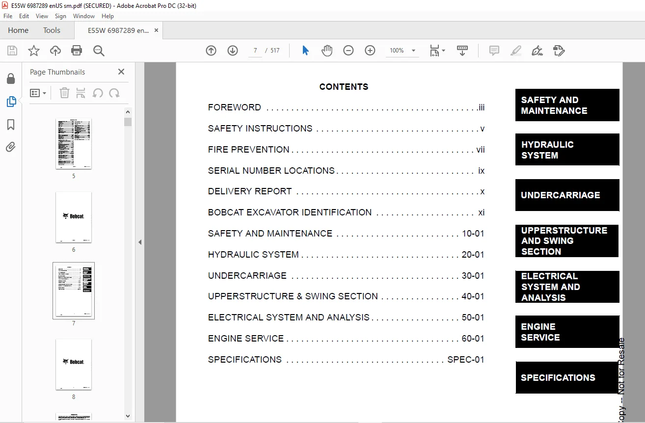
TABLE OF CONTENTS:
Bobcat E55W Excavator Service Manual SN AEFB11001 & Above – PDF DOWNLOAD
MAINTENANCE SAFETY 3
ALPHABETICAL INDEX 5
CONTENTS 7
FOREWORD 9
SAFETY INSTRUCTIONS 11
FIRE PREVENTION 13
Maintenance 13
Operation 13
Electrical 13
Hydraulic System 13
Fueling 13
Starting 13
Spark Arrestor Exhaust System 13
Welding And Grinding 14
Fire Extinguishers 14
SERIAL NUMBER LOCATIONS 15
Excavator Serial Number 15
Engine Serial Number 15
DELIVERY REPORT 16
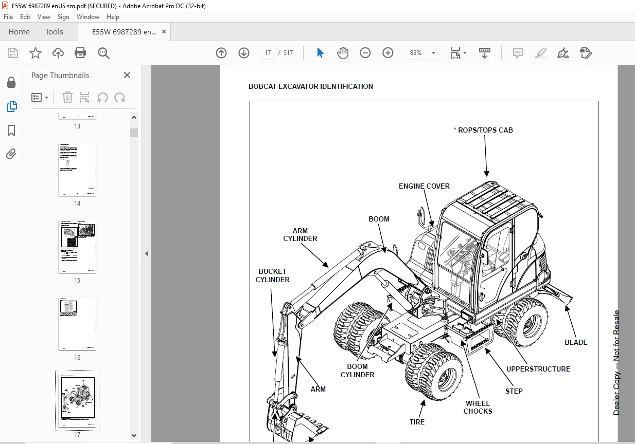
BOBCAT EXCAVATOR IDENTIFICATION 17
SAFETY AND MAINTENANCE 19
LIFTING AND BLOCKING THE EXCAVATOR 21
Procedure 21
UPPERSTRUCTURE SLEW LOCK 23
Upperstructure Slew Lock Pin 23
Boom Swing Lock Pin 24
LIFTING THE EXCAVATOR 25
TRANSPORTING THE EXCAVATOR 27
Loading Onto Transport Vehicle 27
TAILGATE 31
Opening And Closing The Tailgate 31
RIGHT SIDE COVER 33
Opening And Closing The Right Side Cover 33
SERVICE SCHEDULE 35
Chart 35
AIR CLEANER 37
Cleaning Outer And Inner Filters 37
Replacing The Filters 38
COOLING SYSTEM 39
Cleaning The Cooling System 39
Checking The Coolant Level 39
Replacing The Coolant 40
FUEL SYSTEM 41
Fuel Specifications 41
Biodiesel Blend Fuel 41
Filling The Fuel Tank 42
Removing Water From The Fuel Filter 43
Removing Air From The Fuel System 43
Replacing The Fuel Filter 44
ENGINE LUBRICATION SYSTEM 45
Checking Engine Oil 45
Replacing Oil And Filter 46
HYDRAULIC SYSTEM 47
Checking And Adding Hydraulic Oil 47
Replacing The Hydraulic Oil Return Filter 48
Replacing Pilot Filter 49
Replacing Hydraulic Oil 50
LUBRICATION OF THE HYDRAULIC EXCAVATOR 53
Lubrication Locations 53
Grease Boom Swing Cylinder 55
Grease Driveshafts 56
Grease Front Axle Steering Knuckle 57
DRAINING AND REFILLING TRANSMISSION AND AXLE 59
Draining And Refilling Transmission Fluid 59
Draining And Refilling Front Axle Case Oil 59
Draining And Refilling Rear Axle Case Oil 60
Draining And Refilling Hub Reduction Gear Oil 60
ALTERNATOR BELT 61
Adjusting The Alternator Belt 61
Belt Replacement 62
SEAT BELT 63
Inspection And Maintenance 63
CONTROL CONSOLE LOCKOUTS 65
Inspection And Maintenance 65
Safety Precautions 65
EXCAVATOR STORAGE AND RETURN TO SERVICE 67
Storage 67
Return To Service 67
STOPPING THE ENGINE AND LEAVING THE EXCAVATOR 69
Engine Shut Down 69
HYDRAULIC SYSTEM 71
HYDRAULIC SYSTEM INFORMATION 77
Glossary Of Hydraulic/Hydrostatic Symbols For Excavators 77
Troubleshooting The Hydraulic Circuit 81
Troubleshooting The Swing (Upperstructure Slew) Circuit 82
Troubleshooting The Travel Circuit 84
Troubleshooting The Control Valve 85
Troubleshooting The Joystick Control Valve 86
BOOM CYLINDER 87
Boom Cylinder Natural Drop Test 87
Parts Identification 88
Disassembly 89
Assembly 94
ARM CYLINDER 97
Arm Cylinder Natural Drop Test 97
Parts Identification 98
Disassembly 99
Assembly 104
BOOM SWING CYLINDER 107
Parts Identification 107
Disassembly 108
Assembly 113
BUCKET CYLINDER 117
Bucket Cylinder Natural Drop Test 117
Parts Identification 118
Disassembly 119
Assembly 124
BLADE CYLINDER 127
Blade Cylinder Natural Drop Test 127
Parts Identification 128
Disassembly 129
Assembly 134
Frame leveling CYLINDER 137
Parts Identification 137
MAIN RELIEF VALVE 139
Testing And Adjusting The Main Relief Valve (P1 And P2 Rise Type) 139
Testing And Adjusting The Main Relief Valve (P3) 140
OVERLOAD RELIEF VALVES 141
Testing And Adjusting The Overload Relief Valves 141
HYDRAULIC CONTROL VALVE 143
Description 143
Identification Chart 144
Disassembly 145
Straight Travel Valve Section Disassembly And Assembly 146
Slew Valve Section Disassembly And Assembly 147
Boom Swing Valve Section Disassembly And Assembly 148
Tilting Valve Section (Optional) Disassembly And Assembly 149
Blade Valve Section Disassembly And Assembly 150
Boom 2 / Auxiliary Valve Section Disassembly And Assembly 151
Arm 1 Section Disassembly And Assembly 152
Rotary Valve Section Disassembly And Assembly 153
Left Travel Valve Section Disassembly And Assembly 154
Inlet/outlet Valve Section Disassembly And Assembly 155
Right Travel Valve Section Disassembly And Assembly 156
Boom 1 Valve Section Disassembly And Assembly 157
Bucket Valve Section Disassembly And Assembly 158
Arm 2 Valve Section Disassembly And Assembly 159
Assembly 160
TRAVEL MOTOR 165
Parts Identification 165
Disassembly 166
Inspection 170
Assembly 172
SWIVEL JOINT 177
Description 177
Parts Identification 178
Disassembly And Assembly 179
SWING MOTOR 181
Disassembly 183
Motor Disassembly 183
Reduction Gear Disassembly 189
Motor Assembly 192
Reduction Gear Assembly 197
Assembly 200
ACCELERATOR PEDAL VALVE 203
Disassembly And Assembly 203
JOYSTICK 205
Parts Identification 205
Disassembly And Assembly 206
FRAME LEVELING LOCK VALVE 209
Parts Identification 209
Disassembly And Assembly 210
Oil Leakage Test 211
Operational Test 211
STEERING CYLINDER 213
Alignment 213
Disassembly And Assembly 214
Inspection 214
STEERING VALVE 215
General Description 215
Parts Identification 216
Parts Identification (Cont’d) 217
Disassembly 218
Assembly 224
SERVICE BRAKE PEDAL VALVE 237
Parts Identification 237
Disassembly And Assembly 238
BLADE VALVE 245
Parts Identification 245
Disassembly And Assembly 246
UNDERCARRIAGE 249
AXLE 251
Safety Precautions 251
Axle Identification 251
Maintenance Points 252
Maintenance Intervals 252
Planetary Carrier And Wheel Hub Parts 253
Planetary Carrier Disassembly 254
Wheel Hub Disassembly 256
Steering Knuckle And Drive Shaft Parts Identification 259
Steering Knuckle Disassembly 260
Axle Housing / Drive Shaft Disassembly 264
Brakes Group Disassembly And Assembly 267
Bevel Pinion Disassembly 270
Differential Disassembly 271
Differential Assembly 273
Bevel Pinion Assembly 277
Axle Housing / Drive Shaft Assembly 282
Steering Knuckle Assembly 285
Wheel Hub Assembly 291
Planetary Carrier Assembly 292
Trouble Shooting 295
Axle TOE-IN 297
Adjustment 297
STEERING ANGLE ADJUSTMENT 299
Adjustment 299
DRIVE SHAFT 301
Removal And Installation 301
TIRES AND WHEELS 303
Tire Changing Procedure 303
SWING BEARING 305
Operating Recommendation 305
Measuring Swing Bearing Lateral Play 305
Swing Bearing Basic Operation 305
Measuring Swing Bearing Axial Play 305
Parts Identification 306
Disassembly And Assembly 307
TRANSMISSION 309
Transmission Serial Number 309
Maintenance Points 309
Replacing Speed Sensor 310
Hydraulic Gear Control Parts Identification 311
Hydraulic Gear Control Disassembly 312
Hydraulic Gear Control Assembly 316
Reduction Gear Parts Identification 321
Reduction Gear Disassembly 322
Reduction Gear Assembly 331
UPPERSTRUCTURE & SWING SECTION 345
CAB 347
Removal And Installation 347
FUEL TANK 349
Removal 349
Installation 351
BOOM 355
Description 355
Removal And Installation 355
ARM 357
Description 357
Removal 357
Installation 358
BUCKET 359
Bucket Removal 359
Bucket Installation 359
Reversing The Bucket 360
Bucket O-ring Replacement 360
Bucket Tooth Inspection And Replacement 362
COUNTERWEIGHT 363
Removal 363
Installation 364
ELECTRICAL SYSTEM AND ANALYSIS 365
ELECTRICAL SYSTEM INFORMATION 368
Glossary Of Electrical Symbols 368
Troubleshooting 371
BATTERY 372
Servicing 372
Using a booster battery (Jump Starting) 373
ALTERNATOR 374
Parts Identification 374
Wiring Diagram 375
Alternator Standard Output 376
Alternator Specifications 376
Removal 376
Disassembly And Assembly 377
Installation 379
STARTER 380
Parts Identification 380
Removal And Installation 381
Disassembly 382
Cleaning And Inspection 385
No-Load Test 390
FUEL LEVEL SENDER 392
Removal And Installation 392
Testing 392
DIAGNOSTIC SERVICE CODES 394
Description 394
Service Codes List 395
ENGINE SERVICE 400
ENGINE INFORMATION 402
Description 402
ENGINE INFORMATION (Cont’d) 403
Specifications 403
Fuel Injection Nozzles 403
Fuel Injection Pump 403
Cylinder Head 403
Valves 403
Valve Springs 404
Valve Timing 404
Rocker Arms 404
Camshaft 404
Tappet 404
ENGINE INFORMATION (Cont’d) 405
ENGINE INFORMATION (Cont’d) 406
ENGINE INFORMATION (Cont’d) 408
ENGINE INFORMATION (Cont’d) 409
ENGINE INFORMATION (Cont’d) 410
ENGINE INFORMATION (Cont’d) 411
ENGINE INFORMATION (Cont’d) 412
ENGINE INFORMATION (Cont’d) 413
ENGINE SPEED CONTROL 414
Adjustment 414
ENGINE SPEED CONTROL (Cont’d) 415
Adjustment (Cont’d) 415
ENGINE SPEED CONTROL (Cont’d) 416
Adjustment (Cont’d) 416
ENGINE SPEED CONTROL (Cont’d) 417
Adjustment (Cont’d) 417
ENGINE COOLING SYSTEM 418
Engine Cooling System Check 418
Cooling System Draining 419
Water Pump Removal And Installation 420
Water Pump Parts Identification 421
Water Pump Disassembly And Assembly 422
Cleaning And Inspection 423
LUBRICATION SYSTEM 426
Lubrication System Diagram 426
Oil Pan Removal And Installation 427
Oil Pump Removal And Installation 428
Oil Pump Cleaning And Inspection 430
Engine Oil Pressure – Testing 431
FUEL SYSTEM 432
Fuel Injection Pump Removal 432
Fuel Injection Pump Installation 436
Fuel Injection Pump – Timing 440
Fuel Injectors Removal And Installation 445
Fuel Injector Nozzle Pressure – Checking 446
Nozzle Spray Condition 446
Fuel Injector Disassembly And Inspection 447
CYLINDER HEAD 450
Valve Clearance Adjustment 450
4-Valve Cylinder Head Removal And Installation 453
4-Valve Cylinder Head Disassembly And Assembly 456
Push Rod Inspection 457
Rocker Arm Assembly Inspection 457
Valve Guide Inspection 458
Cylinder Head Inspection 459
Intake And Exhaust Valve Inspection 459
Valve Spring Inspection 462
CRANKSHAFT AND PISTONS 464
Parts Identification 464
Piston And Connecting Rod Removal 466
Piston And Connecting Rod – Servicing 468
Cylinder Bore – Checking 471
Crankshaft And Bearings Removal And Installation 472
Cylinder Bore – Honing And Boring 474
Crankshaft And Bearings – Servicing 475
Replacement Of Crankshaft Oil Seals 476
Piston And Connecting Rod Insatallation 477
CAMSHAFT AND TIMING GEARS 480
Timing Gearcase Cover Removal And Installation 480
Timing Gear Backlash – Checking 480
Timing Gears Removal And Installation 481
Camshaft – Servicing 484
Idler Gear And Shaft – Servicing 486
EGR SYSTEM 488
Parts Identification 488
Removal And Installation 489
Cleaning And Inspection 489
SPECIFICATIONS 490
SPECIFICATIONS E55W EXCAVATOR 492
Machine dimensions 492
Working range 493
Lift Capacity (Object handling applications excluded) 494
Performance 495
Function Time 495
Weights 495
Controls 495
Engine 496
Electrical 496
Hydraulic system 496
Hydraulic cylinders 497
Drive system 497
Traction 497
Instrumentation 498
Fluid capacities 498
Fluid specifications 499
Environmental 500
Standard features 500
Options 500
Attachments 500
ENGINE SPECIFICATIONS 502
Engine 502
Fuel Injector Nozzles 502
Fuel Injection Pump 502
Cylinder Head 502
Valves 502
Valve Springs 502
Rocker Arms 503
Camshaft 503
Cylinders 503
Piston Rings 503
Pistons 504
Connecting Rods 504
Crankshaft 504
Oil Pump 504
Thermostat 504
Torque Values 505
TORQUE SPECIFICATIONS 506
Torque For General SAE Bolts 506
Torque For General Metric Bolts 507
HYDRAULIC CONNECTION SPECIFICATIONS 508
O-Ring Face Seal Connection 508
Straight Thread O-Ring Fitting 509
Tubelines And Hoses 509
Flare Fitting 509
Port Seal Fitting 510
HYDRAULIC FLUID SPECIFICATIONS 512
Specifications 512
FUEL, COOLANT AND LUBRICANTS 514
Chart 514
CONVERSIONS 516
Decimal And Millimeter Equivalents 516
U S To Metric Conversion Chart 517
e55-hyd-combined (linked) pdf 0
e55-legend 75
e55-hyd pdf 76
Questions? Email us: [email protected]
https://vimeo.com/841830698?share=copy
PLEASE NOTE:
- This is the SAME exact manual used by your dealers to fix your vehicle.
- The same can be yours in the next 2-3 mins as you will be directed to the download page immediately after paying for the manual.
- Any queries / doubts regarding your purchase, please feel free to contact [email protected]
s.m