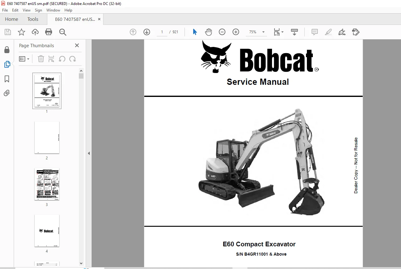
Bobcat E60 Compact Excavator Service Manual SN B4GR11001 & Above – PDF DOWNLOAD
$33.95
Bobcat E60 Compact Excavator Service Manual SN B4GR11001 & Above – PDF DOWNLOAD
S/N B4GR11001 & Above
Description
Bobcat E60 Compact Excavator Service Manual SN B4GR11001 & Above – PDF DOWNLOAD
FILE DETAILS:
Bobcat E60 Compact Excavator Service Manual SN B4GR11001 & Above – PDF DOWNLOAD
Language : English
Pages :921
Downloadable : Yes
File Type : PDF
DESCRIPTION:
Bobcat E60 Compact Excavator Service Manual SN B4GR11001 & Above – PDF DOWNLOAD
FOREWORD
This manual is for the Bobcat excavator mechanic. It provides necessary servicing and adjustment procedures for the Bobcat excavator and its component parts and systems. Refer to the Operation & Maintenance Manual for operating instructions, starting procedure, daily checks, etc.
SAFETY INSTRUCTIONS
Instructions are necessary before operating or servicing machine. Read and understand the Operation & Maintenance Manual, Operator’s Handbook and signs (decals) on machine. Follow warnings and instructions in the manuals when making repairs, adjustments or servicing. Check for correct function after adjustments, repairs or service. Untrained operators and failure to follow instructions can cause injury or death.
The following publications provide information on the safe use and maintenance of the Bobcat machine and attachments:
- The Delivery Report is used to assure that complete instructions have been given to the new owner and that the machine is in safe operating condition.
- The Operation & Maintenance Manual delivered with the machine or attachment contains operating information as well as routine maintenance and service procedures. It is a part of the machine and can be stored in a container provided on the machine. Replacement Operation & Maintenance Manuals can be ordered from your Bobcat dealer.
- Machine signs (decals) instruct on the safe operation and care of your Bobcat machine or attachment. The signs and their locations are shown in the Operation & Maintenance Manual. Replacement signs are available from your Bobcat dealer.
- An Operator’s Handbook fastened to the operator cab. It’s brief instructions are convenient to the operator. The handbook is available from your dealer in an English edition or one of many other languages. See your Bobcat dealer for more information on translated versions.
- The AEM Safety Manual delivered with the machine gives general safety information.
- The Service Manual and Parts Manual are available from your dealer for use by mechanics to do shoptype service and repair work.
IMAGES PREVIEW OF THE MANUAL:
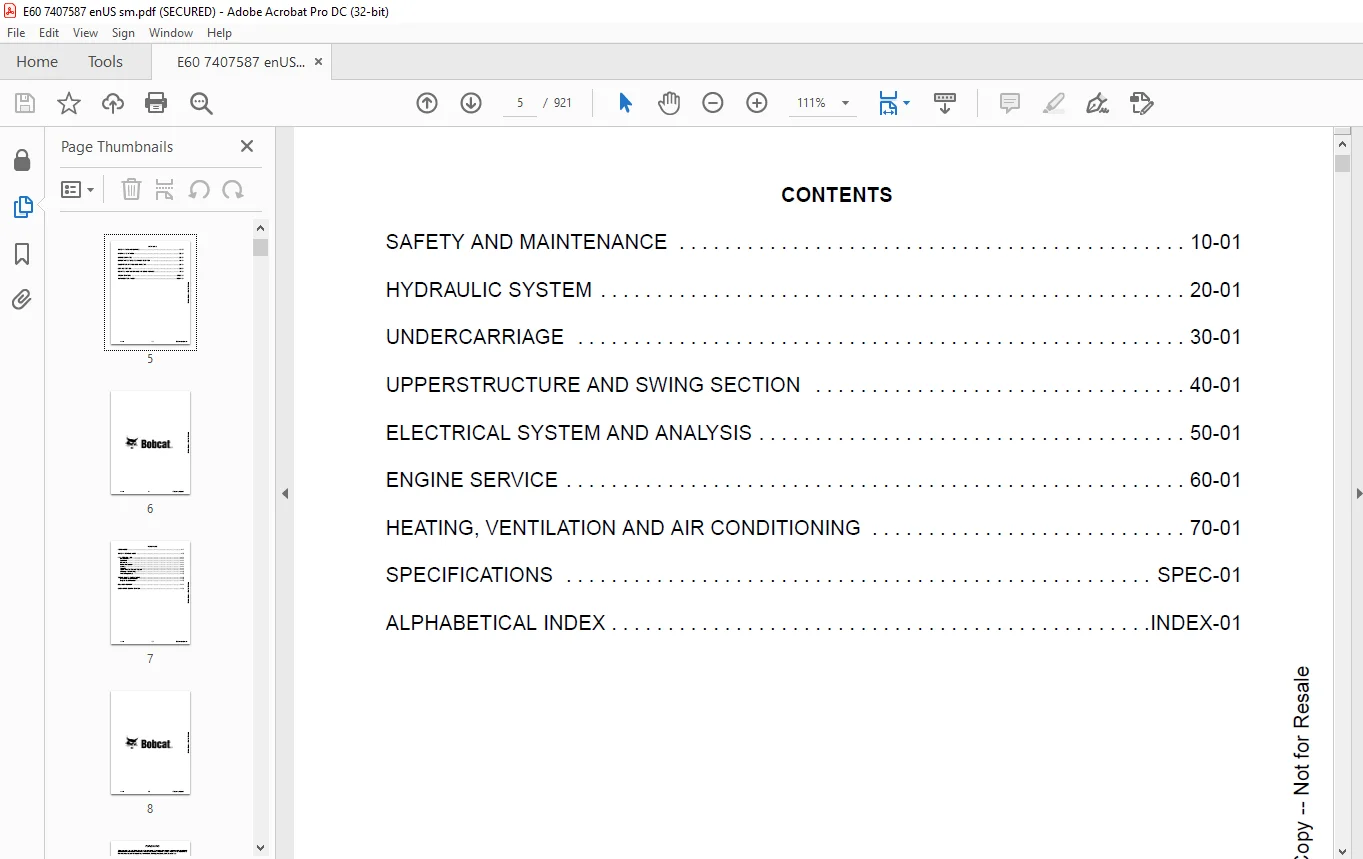
TABLE OF CONTENTS:
Bobcat E60 Compact Excavator Service Manual SN B4GR11001 & Above – PDF DOWNLOAD
MAINTENANCE SAFETY 3
CONTENTS 5
FOREWORD 7
FOREWORD 9
SAFETY INSTRUCTIONS 11
FIRE PREVENTION 13
Maintenance 13
Operation 13
Electrical 13
Hydraulic System 13
Fueling 13
Starting 13
Spark Arrester Exhaust System 13
Welding And Grinding 14
Fire Extinguishers 14
SERIAL NUMBER LOCATIONS 15
Excavator Serial Number 15
Engine Serial Number 15
DELIVERY REPORT 16
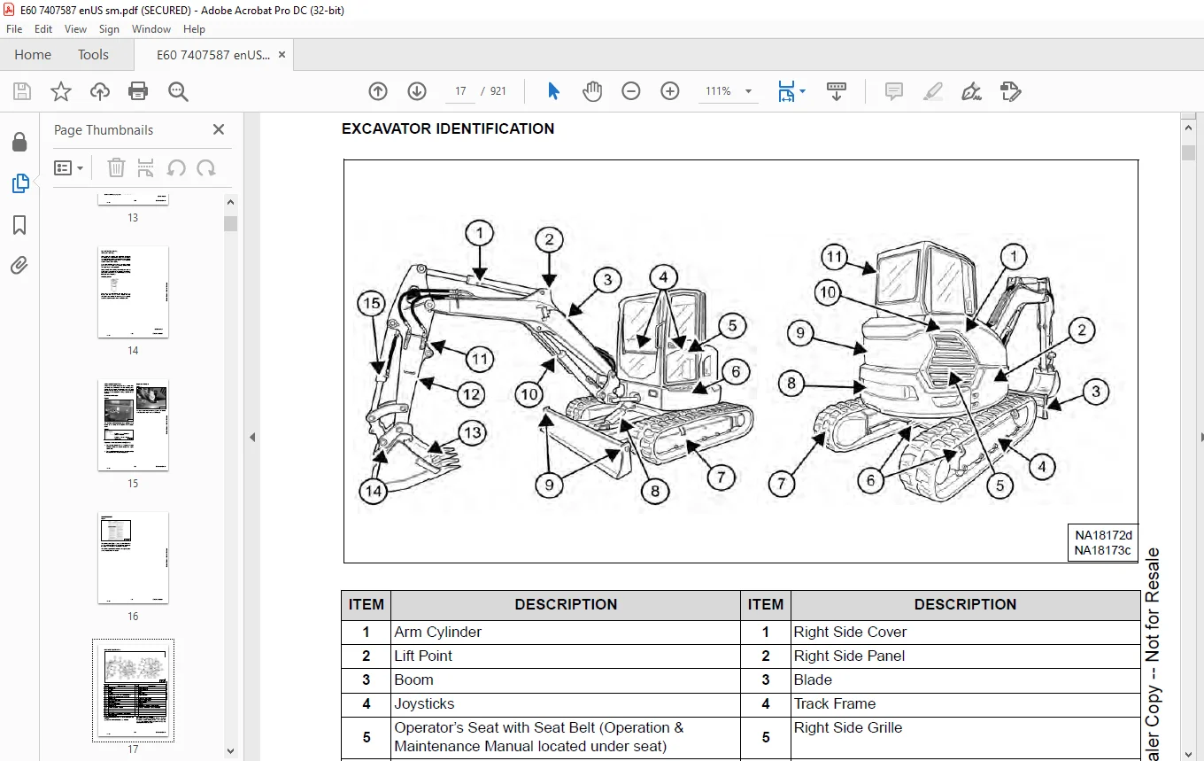
EXCAVATOR IDENTIFICATION 17
SAFETY AND MAINTENANCE 19
LIFTING AND BLOCKING THE EXCAVATOR 21
Procedure 21
LIFTING THE EXCAVATOR 23
Procedure 23
OPERATOR CAB (ROPS / TOPS / FOPS) 25
Description 25
Cab Door 26
Front Window 27
Front Wiper 28
Window Washer Reservoir 28
Right Side Windows 29
OPERATOR CANOPY (ROPS / TOPS / FOPS) 31
Description 31
TRANSPORTING THE EXCAVATOR ON A TRAILER 33
Loading And Unloading 33
Fastening 34
TAILGATE 35
Opening And Closing 35
Adjusting The Latch 35
RIGHT SIDE COVER 37
Opening And Closing 37
SERVICE SCHEDULE 39
Maintenance Intervals 39
Service Schedule 39
AIR CLEANER SERVICE 43
Replacing The Filter Elements 43
CAB FILTERS 45
Cleaning And Maintenance 45
ENGINE COOLING SYSTEM 47
Cleaning 47
Checking Level 48
Removing And Replacing Coolant (Cab Models) 49
Removing And Replacing Coolant (Canopy Models) 50
FUEL SYSTEM 53
Fuel Specifications 53
Biodiesel Blend Fuel 53
Filling The Fuel Tank 54
Fuel Filters 55
Draining The Fuel Tank 57
Replacing The Fuel Pre-Filter 58
Replacing The Fuel Tank Vent Filter 59
ENGINE LUBRICATION SYSTEM 61
Checking And Adding Engine Oil 61
Engine Oil Chart 61
Removing And Replacing Oil And Filter 62
HYDRAULIC SYSTEM 63
Checking And Adding Hydraulic Oil 63
Hydraulic / Hydrostatic Fluid Chart 64
Removing And Replacing The Hydraulic Filters 64
Removing And Replacing The Hydraulic Fluid 66
MACHINE LUBRICATION 69
Grease Fitting Locations 69
PIVOT PINS 71
Inspection And Maintenance 71
TRAVEL MOTOR 73
Checking And Adding Oil 73
Removing And Replacing Oil 73
EMERGENCY EXIT 75
Right Side Rear Window 75
Front Window 75
SEAT BELT 77
Inspection And Maintenance 77
CONTROL CONSOLE LOCKOUTS 79
Inspection And Maintenance 79
TOWING THE EXCAVATOR 81
Procedure 81
REMOTE START TOOL (SERVICE TOOL) KIT – 7217666 83
Description 83
Remote Start Tool (Service Tool) – 7022042 84
Excavator Service Tool Harness – 6689747 85
Computer Service Tool Harness – 6689746 86
HYDRAULIC SYSTEM 87
HYDRAULIC / HYDROSTATIC SCHEMATICS 93
HYDRAULIC SYSTEM INFORMATION 95
Glossary Of Hydraulic / Hydrostatic Symbols 95
Troubleshooting The Hydraulic Circuit 98
Troubleshooting The Cylinder Circuit 99
Troubleshooting The Swing (Upperstructure Slew) Circuit 100
Troubleshooting The Travel Circuit 101
CYLINDER (BOOM) 103
Testing 103
Removal And Installation 105
Parts Identification 108
Disassembly 109
Assembly 112
CYLINDER (ARM) 117
Testing 117
Removal And Installation 119
Parts Identification 121
Disassembly 122
Assembly 124
CYLINDER (BOOM SWING) 127
Testing 127
Removal And Installation 129
Parts Identification 131
Disassembly 132
Assembly 134
CYLINDER (BUCKET) 137
Testing 137
Removal And Installation 139
Parts Identification 141
Disassembly 142
Assembly 144
CYLINDER (BLADE) 147
Testing 147
Removal And Installation 149
Parts Identification 150
Disassembly 151
Assembly 153
CYLINDER (CLAMP) 157
Testing 157
Removal And Installation 158
Parts Identification 160
Disassembly 161
Assembly 163
CYLINDER (ANGLE BLADE) 167
Testing 167
Removal And Installation 168
Parts Identification 170
Disassembly 171
Assembly 173
VALVE (MAIN RELIEF) 177
Testing And Adjusting 177
VALVE (PORT RELIEF) 179
Testing And Adjusting 179
VALVE (CROSS PORT RELIEF) 181
Testing And Adjusting 181
Removal And Installation 184
VALVE (PRESSURE REDUCING) 185
Testing And Adjusting 185
HYDRAULIC CONTROL VALVE 187
Description 187
Removal And Installation 187
Parts Identification 191
Disassembly And Assembly 192
Inlet Valve Section Disassembly And Assembly 196
Boom Swing Valve Section Disassembly And Assembly 199
Slew Valve Section Disassembly And Assembly 202
Blade Valve Section Disassembly And Assembly 205
Right And Left Travel Valve Section Disassembly And Assembly 208
Angle Blade Valve Section Disassembly And Assembly 211
Boom, Auxiliary, Arm, And Bucket Valve Section Disassembly And Assembly 214
HYDRAULIC PUMP 217
Hydraulic Pump Work Sheet 217
Pump Testing 220
Removal And Installation 229
Coupler Removal And Installation 230
Hydraulic Pump Startup 231
Torque Limiter Assembly Parts Identification 232
Torque Limiter Assembly Removal And Installation 233
Torque Limiter Valve Assembly Disassembly And Assembly 233
Pump Control Parts Identification 234
Pump Control Removal And Installation 235
Pump Control Disassembly And Assembly 235
MANIFOLD ASSEMBLY / ACCUMULATOR (WITHOUT ANGLE BLADE) 243
Description 243
Removal And Installation 243
Parts Identification 245
Disassembly And Assembly 246
MANIFOLD ASSEMBLY / ACCUMULATOR (WITH ANGLE BLADE) 253
Description 253
Removal And Installation 253
Parts Identification 255
Disassembly And Assembly 256
TRAVEL MOTOR 263
Removal And Installation 263
Parts Identification Hydraulic Motor 264
Parts Identification Gear Reduction Hub 265
Disassembly 266
Assembly 274
SWIVEL JOINT (WITH STANDARD BLADE) 283
Removal And Installation 283
Parts Identification Standard Blade Swivel 285
Disassembly And Assembly 286
SWIVEL JOINT (WITH ANGLE BLADE) 289
Removal And Installation 289
Parts Identification Angle Blade Swivel 291
Disassembly And Assembly 292
SWING MOTOR 295
Removal And Installation 295
Parts Identification 297
Disassembly And Assembly 298
SWING MOTOR (DRIVE CARRIER) 307
Removal And Installation 307
Parts Identification 308
Disassembly And Assembly 309
CONTROL PATTERN SELECTOR VALVE 315
Removal And Installation 315
Parts Identification 316
Disassembly And Assembly 317
RIGHT CONTROL LEVER (JOYSTICK) 319
Testing 319
Handle Removal And Installation 320
Joystick Assembly Removal And Installation 322
Parts Identification 323
Disassembly 324
Assembly 328
LEFT CONTROL LEVER (JOYSTICK) 333
Testing 333
Handle Removal And Installation 334
Joystick Assembly Removal And Installation 336
Parts Identification 337
Disassembly 338
Assembly 342
HYDRAULIC FILTER MOUNT 347
Removal And Installation 347
HYDRAULIC RESERVOIR 349
Removal And Installation 349
OIL COOLER 351
Description 351
Removal And Installation 351
BLADE CONTROL LEVER 353
Handle Removal And Installation 353
Removal And Installation 354
Parts Identification 355
Disassembly And Assembly 356
CASE DRAIN FILTER MOUNT 361
Removal And Installation 361
TRAVEL CONTROL VALVE 363
Removal And Installation 363
Parts Identification 364
Disassembly And Assembly 365
REMOVING AIR FROM THE HYDRAULIC SYSTEM 371
Procedure 371
MANIFOLD (HYDRAULIC X-CHANGE) 373
Removal And Installation 373
Parts Identification 374
Disassembly And Assembly 375
MANIFOLD (PIN GRABBER) 381
Removal And Installation 381
Parts Identification 382
Disassembly And Assembly 383
SECONDARY AUXILIARY VALVE 385
Removal And Installation 385
Parts Identification 387
Disassembly And Assembly 388
VALVE (BOOM LOCK) 391
Removal And Installation 391
VALVE (ARM LOCK) 393
Removal And Installation 393
UNDERCARRIAGE 395
BLADE 397
Removal And Installation 397
BLADE (ANGLE) 399
Removal And Installation 399
Cutting Edge Removal And Installation 400
TRACK UNDERCARRIAGE COMPONENTS (RUBBER TRACK) 401
Description 401
Track Lug Height 401
Checking / Adjusting Tension 402
Track Removal And Installation 404
Idler Removal And Installation 405
Idler Parts Identification 406
Idler Disassembly 407
Idler Assembly 409
Track Tensioner Removal And Installation 412
Track Tensioner Parts Identification 413
Track Tensioner Disassembly And Assembly 414
Roller Removal And Installation 416
Sprocket Removal And Installation 416
TRACK UNDERCARRIAGE COMPONENTS (STEEL TRACK) 417
Description 417
Checking / Adjusting Tension 418
Track Removal 420
Track Installation 423
Idler Removal And Installation 425
Idler Parts Identification 426
Idler Disassembly 427
Idler Assembly 429
Track Tensioner Removal And Installation 432
Track Tensioner Parts Identification 433
Track Tensioner Disassembly And Assembly 434
Roller Removal And Installation 436
Sprocket Removal And Installation 437
Guide Plate Removal And Installation 437
TRACK MAINTENANCE 439
Track Damage Identification 439
SWING CIRCLE GEAR 451
Swing Bearing Removal 451
Swing Bearing Installation 452
UPPERSTRUCTURE AND SWING SECTION 453
UPPERSTRUCTURE 457
Removal 457
Installation 459
ROPS CANOPY 461
Removal And Installation 461
CAB 465
Removal And Installation 465
Door Removal And Installation 469
Door Latch Removal And Installation 470
Hold Open Latch Removal And Installation 471
Front Window Removal And Installation 472
Front Window Disassembly And Assembly 473
Front Window Adjustment 475
Right Side Rear Sliding Window Removal And Installation 477
Glass Removal 478
SEAT 479
Removal And Installation 479
RIGHT CONSOLE 481
Console Cover Removal And Installation 481
LEFT CONSOLE 485
Lower Console Cover Removal And Installation 485
Upper Console Cover Removal And Installation 485
Compression Spring Removal And Installation 488
Lock Lever Removal And Installation 490
Console Removal And Installation 490
LEFT UPPERSTRUCTURE COVER 491
Removal And Installation 491
RIGHT UPPERSTRUCTURE COVER 493
Removal And Installation 493
COUNTERWEIGHT 495
Removal And Installation 495
Add-On Counterweight Removal And Installation 498
TRAVEL LEVERS AND PEDALS 499
Removal And Installation 499
Disassembly And Assembly 500
FLOORPLATE 501
Removal And Installation 501
FUEL TANK 503
Removal And Installation 503
HORN 505
Removal And Installation 505
SWING FRAME 507
Removal And Installation 507
Boom Swing Frame Hose Routing 510
Bushing Removal 511
Bushing Installation 512
BOOM 513
Removal And Installation 513
LONG ARM 515
Removal And Installation 515
Arm To Boom Bushing Removal And Installation 516
Arm To Bucket And Bucket Link Bushing Removal And Installation 517
ARM (EXTENDABLE) 519
Removal And Installation 519
Arm To Boom Bushing Removal And Installation 520
Arm To Bucket Bushing Removal And Installation 521
Disassembly And Assembly 522
Shimming Procedure 529
BUCKET 531
Bucket Teeth Removal And Installation 531
Bucket Side Cutting Edge Removal And Installation 532
CLAMP 533
Removal And Installation 533
TAILGATE 535
Removal And Installation 535
Latch Removal And Installation 536
X-CHANGE 537
Removal And Installation 537
Disassembly 538
Assembly 539
X-CHANGE (HYDRAULIC) 541
Removal And Installation 541
Parts Identification 543
Disassembly 544
Assembly 549
QUICK COUPLER (KLAC™ SYSTEM) 557
Troubleshooting 557
Daily Inspection 557
Removal And Installation 558
Parts Identification 560
Disassembly 561
Assembly 563
QUICK COUPLER (LEHNHOFF® SYSTEM) 565
Troubleshooting 565
Daily Inspection 565
Removal (MS03 And MS08) 566
Installation (MS03 And MS08) 567
Parts Identification (MS03) 568
Disassembly And Assembly (MS03) 569
Parts Identification (MS08) 570
Disassembly (MS08) 571
Assembly (MS08) 574
QUICK COUPLER (PIN GRABBER) 579
Troubleshooting 579
Daily Inspection 580
Removal And Installation 580
Parts Identification 582
Disassembly And Assembly 583
RIGHT SIDE COVER 585
Removal And Installation 585
Latch Removal And Installation 586
TOOLBOX 587
Removal And Installation 587
LEFT SIDE GRILLE 589
Removal And Installation 589
LEFT SIDE PANEL 591
Removal And Installation 591
RIGHT SIDE GRILLE 593
Removal And Installation 593
ELECTRICAL SYSTEM AND ANALYSIS 595
ELECTRICAL SCHEMATICS 597
ELECTRICAL SYSTEM INFORMATION 618
Troubleshooting Chart 618
Description 619
Fuse And Relay Location / Identification 619
BATTERY 622
Servicing 622
Maintaining Battery Charge Level 622
Battery Service During Machine Storage 622
Battery Testing 623
Battery Charging 623
Removing And Installing 624
Using A Booster Battery (Jump Starting) 625
ALTERNATOR 626
Belt Adjustment 626
Belt Replacement 626
Charging System Inspection 628
Alternator Voltage Testing 629
Low Voltage Testing 629
High Voltage Testing 630
Removal And Installation 631
Parts Identification 632
STARTER 634
Testing 634
Removal And Installation 635
Parts Identification 636
LIGHTS 638
Removal And Installation 638
Boom Light Removal And Installation 639
MAGNETIC LOCKOUT SENSOR 640
Removal And Installation 640
FUEL LEVEL SENDER 642
Removal And Installation 642
Testing 643
DIAGNOSTIC SERVICE CODES 644
Viewing Service Codes 644
Service Codes List 646
CONTROL PANEL SETUP 656
Panel Setup (Touch Display) 656
STANDARD DISPLAY 666
Removal And Installation 666
TOUCH DISPLAY 668
Removal And Installation 668
Controller Display Removal And Installation 668
CONTROLLER (GATEWAY AND AUXILIARY) 670
Description 670
Gateway Controller Removal And Installation 670
Auxiliary Controller Removal And Installation 671
ENGINE CONTROL UNIT (ECU) 672
Description 672
Cleaning 673
Removal And Installation 674
KEY SWITCH 678
Removal And Installation 678
WIPER MOTOR 680
Removal And Installation 680
MOTION ALARM SYSTEM 682
Description 682
Inspecting 682
Switch Removal And Installation 683
SERVICE PC (LAPTOP COMPUTER) 684
Connecting The Remote Start Tool 684
Connecting Remote Start Tool (Service Tool) 684
SHUT-OFF SWITCH (IF EQUIPPED) 686
Description 686
Removal And Installation 687
TRAVEL MOTOR AUTO-SHIFT 688
Auto-Shift Drive System 688
Troubleshooting 689
AUTO IDLE PRESSURE SENSOR 692
Description 692
Removal And Installation 693
BOBCAT MACHINE IQ WIRELESS COMMUNICATIONS 694
Description 694
ENGINE SERVICE 698
ENGINE INFORMATION 702
Description 702
Specifications 703
Sensor Location 705
Torque Values 711
Troubleshooting 713
Engine Removal And Installation 715
Compression – Testing (Using Glow Plug Compression Adapter) 722
Compression – Testing (Using Injector Compression Adapter) 724
Injector Signal – Testing 726
Injector Signal – Testing (In-Line) 727
DIESEL OXIDATION CATALYST (DOC) 728
Removal And Installation 728
AIR CLEANER 730
Housing Removal And Installation 730
ENGINE COOLING SYSTEM 732
Description 732
Radiator Cooling Package Removal And Installation 733
Fan Removal And Installation 736
Water Pump Removal And Installation 737
Thermostat Housing Removal And Installation 738
Testing The Thermostat 738
LUBRICATION SYSTEM 740
Description 740
Oil Pan Removal And Installation 741
Oil Pump Removal And Installation 742
Oil Pump Relief Valve Description 743
Oil Pump Relief Valve Removal And Installation 743
Oil Cooler / Oil Filter Module Removal And Installation 743
Oil Cooler / Oil Filter Module Disassembly and Assembly 744
FUEL SYSTEM 746
Description 746
Fuel Filter Housing Removal And Installation 747
Fuel Lift Pump Removal And Installation 749
Fuel Lift Pump Filter Removal And Installation 750
Transfer Pump / High Pressure Pump Removal And Installation 750
Fuel Temperature Sensor Removal And Installation 752
Fuel Recirculation Valve (FRV) Removal And Installation 753
Fuel Pressure Relief Valve Removal And Installation 753
Fuel Rail Assembly Removal And Installation 754
Fuel Injector Removal And Installation 755
Injector Coding 758
CYLINDER HEAD 760
Glow Plugs Testing 760
Glow Plug Removal And Installation 761
Cylinder Head Removal And Installation 762
Cylinder Head Disassembly And Assembly 765
Cylinder Head Inspection 766
Cylinder Head Top Clearance 767
Valve Step Height 768
Valve Stem Height 768
Valve Guide 769
Valve 769
Valve Spring 770
Rocker Arm Shaft Disassembly And Assembly 771
Rocker Arm Shaft Inspection 772
Push Rod Inspection 772
CRANKSHAFT AND PISTONS 774
Piston And Connecting Rod Removal And Installation 774
Piston And Connecting Rod Inspection 775
Crankshaft Removal And Installation 777
Cylinder Block Inspection 780
Crankshaft Inspection 782
Connecting Rod Inspection 782
Engine Component Class 783
CAMSHAFT 786
Removal And Installation 786
Inspecting 787
GEARCASE 790
Gearcase Cover Removal And Installation 790
Gear Backlash 791
Gear Timing 792
Idle Gear Removal And Installation 793
Idle Gear Inspection 793
TURBOCHARGER 794
Description 794
Removal And Installation 794
Inspection 796
FLYWHEEL AND HOUSING 798
Hydraulic Pump Coupler Removal And Installation 798
Flywheel Removal And Installation 800
Ring Gear Removal And Installation 800
EXHAUST GAS RECIRCULATION (EGR) SYSTEM 802
Description 802
Removal And Installation 803
EXHAUST MANIFOLD 806
Removal And Installation 806
INTERCOOLER 808
Description 808
Removal And Installation 808
HEATING, VENTILATION AND AIR CONDITIONING 810
AIR CONDITIONING SYSTEM FLOW 812
Description 812
Chart 813
Components 814
Safety Equipment 817
REGULAR MAINTENANCE 818
Cab Filters 818
Air Conditioning Compressor Belt Adjustment 819
Air Conditioning Compressor Belt Replacement 819
Condenser 820
Air Conditioning Lubrication 820
Evaporator / Heater Coil 820
Air Conditioning Service Chart 822
TROUBLESHOOTING 824
Blower Motor Does Not Operate 824
Blower Motor Operates Normally, But Air Flow Is Insufficient 824
Insufficient Cooling Although Air Flow And Compressor Operation Are Normal 824
The Compressor Operates Improperly Or Not At All 824
Gauge Pressure Related Troubleshooting 825
Temperature / Pressure Chart 826
Poor A/C Performance 827
HVAC Repair And Leaks 827
Electrical System 828
Engine Coolant Bypassing The Heater Valve 830
SYSTEM CHARGING AND RECLAMATION 832
Refrigerant Identification 832
Reclamation And Charging With Recovery / Charging Unit 834
COMPRESSOR 836
Removal And Installation 836
Oil 837
Oil Check 838
CONDENSER 840
Removal And Installation 840
RECEIVER / DRIER 842
Receiver / Drier Removal And Installation 842
Pressure Switch Removal And Installation 843
EVAPORATOR / HEATER UNIT 844
Removal And Installation 844
THERMOSTAT 846
Description 846
Removal And Installation 847
AIR SENSOR 850
Location 850
Inside And After Air Sensor Removal And Installation 851
EXPANSION VALVE 852
Removal And Installation 852
EVAPORATOR COIL 854
Removal And Installation 854
AUTO EVAPORATOR COIL 856
Removal And Installation 856
HEATER COIL 858
Removal And Installation 858
AUTO HEATER COIL 860
Removal And Installation 860
BLOWER FAN 862
Removal And Installation 862
AUTO BLOWER FAN 864
Removal And Installation 864
HEATER VALVE 866
Removal And Installation 866
CONTROL PANEL 868
Removal And Installation 868
HVAC DUCT 870
Removal And Installation 870
AUTO HVAC 872
Description 872
ATM Removal And Installation 872
ATM Diagnostic Codes 873
Blower Fan Drive Assembly Removal And Installation 874
De-Icing Sensor Removal And Installation 875
Inside And After Coil Sensor Testing 875
SPECIFICATIONS 878
EXCAVATOR SPECIFICATIONS 880
Machine Dimensions 880
Performance Specifications 886
Controls Specifications 886
Engine Specifications 887
Hydraulic System Specifications 887
Hydraulic Cylinders 888
Hydraulic Cycle Times 888
Electrical Specifications 888
Drive System Specifications 888
Slew System Specifications 889
Undercarriage Specifications 889
Capacities Specifications 889
Tracks Specifications 889
Ground Pressure Specifications 889
TECHNICAL SERVICE GUIDE SPECIFICATIONS 890
Engine 890
Engine Torques 890
Cooling System 890
Excavator Torques 890
TORQUE SPECIFICATION FOR BOLTS 892
Torque For General SAE Bolts 892
Torque For General Metric Bolts 893
HYDRAULIC CONNECTION SPECIFICATIONS 894
O-ring Face Seal Connection 894
Straight Thread O-ring Fitting 894
Tubelines And Hoses 895
Flare Fitting 895
O-ring Flare Fitting 896
Port Seal Fitting 898
Push To Connect Fittings 899
HYDRAULIC FLUID SPECIFICATIONS 902
Specifications 902
CONVERSIONS 904
Decimal And Millimeter Equivalent Chart 904
U S To Metric Conversion Chart 905
SERVICE TOOLS REQUIRED 906
Remote Start Tools 906
Hydraulic Tools 907
Engine Tools 910
Electrical Tools 912
General Tools 913
HVAC Tools 914
ALPHABETICAL INDEX 916
Contact us: [email protected]
https://vimeo.com/841832485?share=copy
PLEASE NOTE:
- This is the SAME exact manual used by your dealers to fix your vehicle.
- The same can be yours in the next 2-3 mins as you will be directed to the download page immediately after paying for the manual.
- Any queries / doubts regarding your purchase, please feel free to contact [email protected]
s.m


