Bobcat E62 Compact Excavator Service Manual SN B34P11001 & Above – PDF DOWNLOAD
$33.95
Bobcat E62 Compact Excavator Service Manual SN B34P11001 & Above – PDF DOWNLOAD
S/N B34P11001 & Above
Description
Bobcat E62 Compact Excavator Service Manual SN B34P11001 & Above0 – PDF DOWNLOAD
FILE DETAILS:
Bobcat E62 Compact Excavator Service Manual SN B34P11001 & Above – PDF DOWNLOAD
Language : English
Pages : 805
Downloadable : Yes
File Type : PDF
Size:23.2 MB
DESCRIPTION:
S/N B34P11001 & Above
Bobcat E62 Compact Excavator Service Manual SN B34P11001 & Above – PDF DOWNLOAD
FOREWORD
This manual is for the Bobcat excavator mechanic. It provides necessary servicing and adjustment procedures for the Bobcat excavator and its component parts and systems. Refer to the Operation & Maintenance Manual for operating instructions, starting procedure, daily checks, etc.
SAFETY INSTRUCTIONS
Instructions are necessary before operating or servicing machine. Read and understand the Operation & Maintenance Manual, Operator’s Handbook and signs (decals) on machine. Follow warnings and instructions in the manuals when making repairs, adjustments or servicing. Check for correct function after adjustments, repairs or service. Untrained operators and failure to follow instructions can cause injury or death.
The following publications provide information on the safe use and maintenance of the Bobcat machine and attachments:
- The Delivery Report is used to assure that complete instructions have been given to the new owner and that the machine is in safe operating condition.
- The Operation & Maintenance Manual delivered with the machine or attachment contains operating information as well as routine maintenance and service procedures. It is a part of the machine and can be stored in a container provided on the machine. Replacement Operation & Maintenance Manuals can be ordered from your Bobcat dealer.
- Machine signs (decals) instruct on the safe operation and care of your Bobcat machine or attachment. The signs and their locations are shown in the Operation & Maintenance Manual. Replacement signs are available from your Bobcat dealer.
- An Operator’s Handbook fastened to the operator cab. It’s brief instructions are convenient to the operator. The handbook is available from your dealer in an English edition or one of many other languages. See your Bobcat dealer for more information on translated versions.
- The AEM Safety Manual delivered with the machine gives general safety information.
- The Service Manual and Parts Manual are available from your dealer for use by mechanics to do shoptype service and repair work.
IMAGES PREVIEW OF THE MANUAL:
TABLE OF CONTENTS:
Bobcat E62 Compact Excavator Service Manual SN B34P11001 & Above – PDF DOWNLOAD
MAINTENANCE SAFETY 3
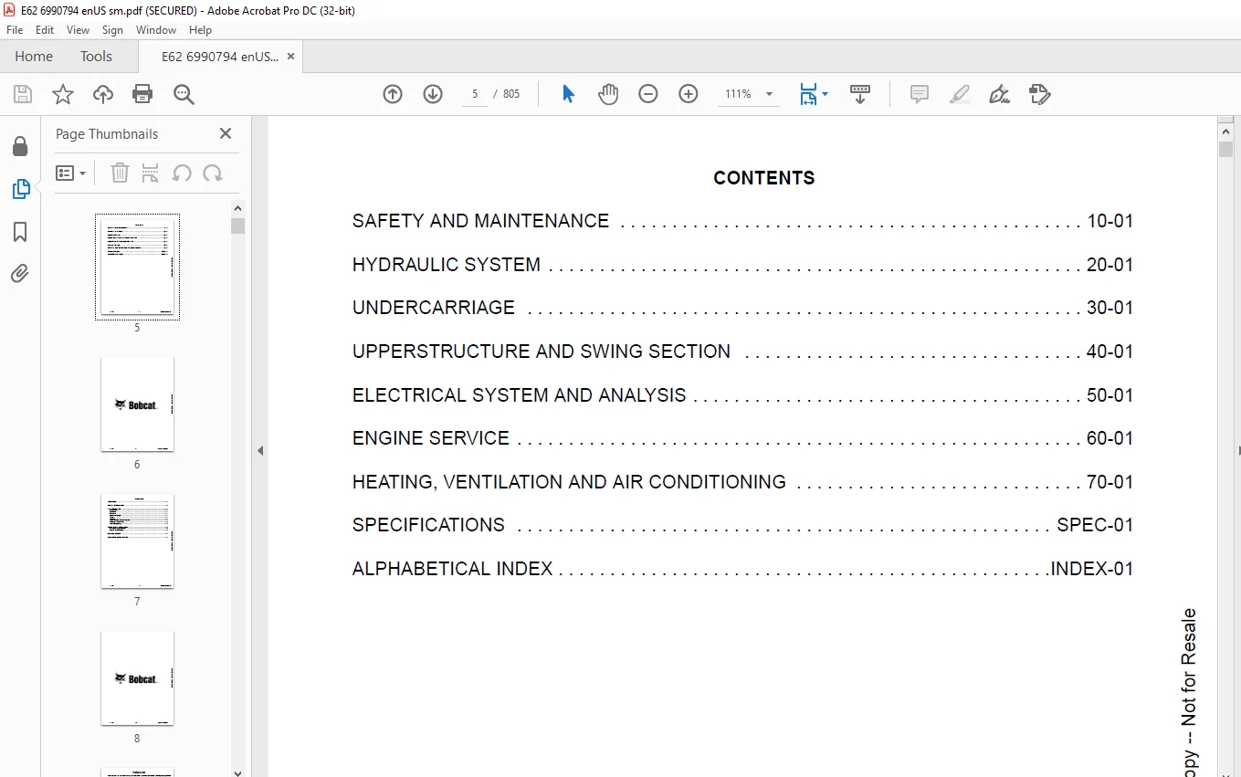
CONTENTS 5
FOREWORD 7
FOREWORD 9
SAFETY INSTRUCTIONS 11
FIRE PREVENTION 13
Maintenance 13
Operation 13
Electrical 13
Hydraulic System 13
Fueling 13
Starting 13
Welding And Grinding 14
Fire Extinguishers 14
SERIAL NUMBER LOCATIONS 15
Excavator Serial Number 15
Engine Serial Number 15
DELIVERY REPORT 16
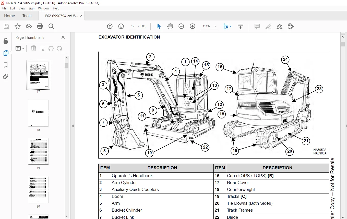
EXCAVATOR IDENTIFICATION 17
SAFETY AND MAINTENANCE 19
LIFTING AND BLOCKING THE EXCAVATOR 21
Procedure 21
LIFTING THE EXCAVATOR 23
Procedure 23
OPERATOR CAB 25
Description 25
Cab Door 25
Front Window 26
Front Wiper 27
Window Washer Reservoir 27
Right Side Window 28
Heating, Ventilation And Air Conditioning Duct 29
TRANSPORTING THE EXCAVATOR ON A TRAILER 31
Loading And Unloading 31
Fastening 32
RIGHT SIDE COVER 33
Opening And Closing 33
Adjusting The Latch 33
REAR COVER 35
Opening And Closing 35
SERVICE SCHEDULE 37
Maintenance Intervals 37
AIR CLEANER SERVICE 39
Daily Check 39
Replacing The Filters 40
CAB FILTERS 41
Cleaning And Maintenance 41
ENGINE COOLING SYSTEM 43
Cleaning 43
Checking Level 43
Removing And Replacing Coolant 44
FUEL SYSTEM 45
Fuel Specifications 45
Biodiesel Blend Fuel 45
Filling The Fuel Tank 46
Fuel Filters 47
Draining The Fuel Tank 49
Removing Air From The Fuel System 49
ENGINE LUBRICATION SYSTEM 51
Checking And Adding Engine Oil 51
Engine Oil Chart 51
Removing And Replacing Oil And Filter 52
HYDRAULIC SYSTEM 55
Checking And Adding Fluid 55
Hydraulic Fluid Chart 56
Removing And Replacing Hydraulic Filters 56
Removing And Replacing Hydraulic Fluid 60
LUBRICATING THE EXCAVATOR 63
Lubrication Locations 63
PIVOT PINS 67
Inspection And Maintenance 67
TRAVEL MOTOR 69
Checking And Adding Oil 69
Removing And Replacing Oil 69
SPARK ARRESTER MUFFLER 71
Cleaning Procedure 71
AIR CONDITIONING BELT 73
Belt Adjustment 73
Belt Replacement 74
EMERGENCY Exits 75
Right Rear Side Window 75
Front Window 75
SEAT BELT 77
Inspection And Maintenance 77
CAB TILT PROCEDURE 79
Tilting The Cab 79
CONTROL CONSOLE LOCKOUT 81
Inspection And Maintenance 81
TOWING THE EXCAVATOR 83
Procedure 83
HYDRAULIC SYSTEM 85
HYDRAULIC / HYDROSTATIC SCHEMATICS 89
HYDRAULIC SYSTEM INFORMATION 91
Glossary Of Hydraulic / Hydrostatic Symbols 91
Troubleshooting The Hydraulic Circuit 94
Troubleshooting The Cylinder Circuit 95
Troubleshooting The Swing (Slew) Circuit 96
Troubleshooting The Travel Circuit 97
CYLINDER (BOOM) 99
Testing 99
Removal And Installation 101
Parts Identification 104
Disassembly 105
Assembly 112
CYLINDER (ARM) 119
Testing 119
Removal And Installation 121
Parts Identification 123
Disassembly 124
Assembly 131
CYLINDER (BOOM SWING) 139
Testing 139
Removal And Installation 140
Parts Identification 143
Disassembly 144
Assembly 151
CYLINDER (BUCKET) 159
Testing 159
Removal And Installation 159
Parts Identification 163
Disassembly 164
Assembly 171
CYLINDER (BLADE) 179
Testing 179
Removal And Installation 180
Parts Identification 183
Disassembly 184
Assembly 189
VALVE (MAIN RELIEF) 195
Testing And Adjusting 195
VALVE (PORT RELIEF) 197
Testing And Adjusting The Port Relief Valve Pressure 197
VALVE (PRESSURE REDUCING) 199
Testing And Adjusting 199
HYDRAULIC CONTROL VALVE 201
Removal And Installation 201
Parts Identification 204
Disassembly And Assembly 205
Inlet Valve Section Disassembly And Assembly 208
Boom Swing Valve Section Disassembly And Assembly 212
Slew Valve Section Disassembly And Assembly 215
Blade Valve Section Disassembly And Assembly 219
Right And Left Travel Valve Section Disassembly And Assembly 223
Boom, Auxiliary, Arm And Bucket Valve Section Disassembly And Assembly 225
HYDRAULIC PUMP 229
Hydraulic Pump Work Sheet 229
Pump Testing 232
Removal And Installation 243
Hydraulic Pump Startup 245
Torque Limiter Assembly Parts Identification 246
Torque Limiter Assembly Removal And Installation 247
Torque Limiter Valve Assembly Disassembly And Assembly 247
Pump Control Parts Identification 248
Pump Control Removal And Installation 249
Pump Control Disassembly And Assembly 249
Parts Identification 255
Disassembly And Assembly 256
MANIFOLD ASSEMBLY / ACCUMULATOR 265
Description 265
Removal And Installation 265
Disassembly And Assembly 266
TRAVEL MOTOR 269
Removal And Installation 269
Parts Identification Hydraulic Motor 270
Parts Identification Gear Reduction Hub 271
Disassembly 272
Assembly 288
SWIVEL JOINT 305
Removal And Installation 305
Parts Identification 308
Disassembly 309
Assembly 310
SWING MOTOR 313
Removal And Installation 313
Parts Identification 315
Disassembly And Assembly 316
SWING MOTOR (DRIVE CARRIER) 325
Removal And Installation 325
Parts Identification 326
Disassembly And Assembly 327
CONTROL PATTERN SELECTOR VALVE 331
Removal And Installation 331
Disassembly And Assembly 332
RIGHT CONTROL LEVER (JOYSTICK) 335
Testing 335
Handle Removal And Installation 336
Joystick Assembly Removal And Installation 337
Parts Identification 339
Disassembly And Assembly 340
LEFT CONTROL LEVER (JOYSTICK) 345
Testing 345
Handle Removal And Installation 346
Joystick Assembly Removal And Installation 347
Parts Identification 349
Disassembly And Assembly 350
BLADE CONTROL VALVE 355
Removal And Installation 355
Parts Identification 356
Disassembly And Assembly 357
HYDRAULIC RESERVOIR 361
Removal And Installation 361
OIL COOLER 365
Removal And Installation 365
DIRECT TO TANK VALVE 367
Removal And Installation 367
Disassembly And Assembly 368
SWING MOTOR BRAKE RELEASE 369
Description 369
Removal And Installation 369
Parts Identification 370
Disassembly And Assembly 371
EPPR VALVE 373
Description 373
Removal And Installation 373
Parts Identification 374
Disassembly And Assembly 375
TRAVEL CONTROL VALVE 377
Removal And Installation 377
Parts Identification 379
Disassembly And Assembly 380
AUTO IDLE 385
Description 385
UNDERCARRIAGE 387
BLADE 389
Removal And Installation 389
TRACK UNDERCARRIAGE COMPONENTS (RUBBER TRACK) 391
Description 391
Track Lug Height 391
Checking Tension 392
Adjusting Tension 393
Track Removal And Installation 393
Idler Removal And Installation 396
Idler Parts Identification 397
Idler Disassembly 398
Idler Assembly 401
Tensioner Removal And Installation 406
Track Tensioner Parts Identification 407
Track Tensioner Disassembly And Assembly 408
Roller Removal And Installation 409
Roller Parts Identification 410
Roller Disassembly 411
Roller Assembly 414
Sprocket Removal And Installation 418
TRACK UNDERCARRIAGE COMPONENTS (STEEL TRACK) 419
Description 419
Checking Tension 420
Adjusting Tension 421
Track Removal 421
Track Installation 424
Idler Removal And Installation 425
Idler Parts Identification 426
Idler Disassembly 427
Idler Assembly 430
Track Tensioner Removal And Installation 435
Track Tension Parts Identification 436
Track Tensioner Disassembly And Assembly 437
Roller Removal And Installation 438
Roller Parts Identification 439
Roller Disassembly 440
Roller Assembly 443
Sprocket Removal And Installation 447
Guide Plate Removal And Installation 447
TRACK MAINTENANCE 449
Track Damage Identification 449
SWING CIRCLE GEAR 461
Swing Bearing Removal 461
Swing Bearing Installation 461
UPPERSTRUCTURE AND SWING SECTION 463
UPPERSTRUCTURE 465
Removal 465
Installation 467
CAB 469
Removal And Installation 469
Door Removal And Installation 479
Front Window Removal And Installation 480
Lower Front Window Removal And Installation 481
Glass Installation 482
Front Window Strut Removal And Installation 487
Front Window Slide Bar Removal And Installation 488
Cab Tilt Assembly Removal And Installation 489
Cab Tilt Parts Identification 490
Cab Tilt Assembly Disassembly And Assembly 491
Headliner Removal And Installation 492
SEAT 497
Seat Removal And Installation 497
Seat Mount Removal And Installation 498
RIGHT CONSOLE 501
Console Cover Removal And Installation 501
LEFT CONSOLE 503
Lower Console Cover Removal And Installation 503
Upper Console Cover Removal And Installation 504
Gas Strut Removal And Installation 505
Lock Lever Removal And Installation 506
Lock Lever Disassembly And Assembly 507
Console Removal And Installation 508
LEFT UPPERSTRUCTURE COVER 509
Removal And Installation 509
RIGHT UPPERSTRUCTURE COVER 511
Removal And Installation 511
COUNTER WEIGHT 513
Removal And Installation 513
FLOOR MAT 515
Removal And Installation 515
FUEL TANK 517
Removal And Installation 517
HORN 519
Removal And Installation 519
SWING FRAME 521
Removal And Installation 521
Bushing Removal 525
Bushing Installation 526
BOOM 527
Removal And Installation 527
Bushing Removal And Installation 528
ARM (STANDARD AND LONG) 529
Removal And Installation 529
Arm To Boom Bushing Removal And Installation 530
Bucket And Link Bushing Removal And Installation 531
BUCKET 533
Bucket Teeth Removal And Installation 533
Bucket Side Cutting Edge Removal And Installation 534
REAR COVER 535
Removal And Installation 535
QUICK COUPLER (KLAC™ SYSTEM) 537
Troubleshooting 537
Daily Inspection 537
Removal And Installation 538
Parts Identification 540
Disassembly 541
Assembly 543
QUICK COUPLER (LEHNHOFF® SYSTEM) 545
Troubleshooting 545
Daily Inspection 545
Removal (MS03 And MS08) 546
Installation (MS03 And MS08) 547
Parts Identification (MS03) 548
Disassembly And Assembly (MS03) 549
Parts Identification (MS08) 550
Disassembly (MS08) 551
Assembly (MS08) 555
RIGHT SIDE COVER 559
Removal And Installation 559
ELECTRICAL SYSTEM AND ANALYSIS 561
ELECTRICAL SCHEMATICS 563
ELECTRICAL SYSTEM INFORMATION 564
Troubleshooting Chart 564
Description 565
Fuse And Relay Location / Identification 565
Engine Control Unit (ECU) 567
Master Disconnect Switch 567
BATTERY 568
Battery Maintenance 568
Using A Booster Battery (Jump Starting) 569
Removing And Installing Battery 570
ALTERNATOR 572
Belt Adjustment 572
Belt Replacement 572
Charging System Inspection 573
Alternator Voltage Testing 575
Removal And Installation 576
STARTER 578
Testing 578
Removal And Installation 579
Parts Identification 581
LIGHTS 582
Boom Light Removal And Installation 582
Boom Light Bulb Replacement 582
CONSOLE LOCKOUT SWITCH 584
Testing / Adjustment 584
Removal And Installation 585
FUEL LEVEL SENDER 586
Removal And Installation 586
DIAGNOSTIC SERVICE CODE 588
Service Codes List 588
Flashing Patterns Of Engine Check Lamp 595
DIAGNOSTIC TOOL 596
Software Installation 596
Installation 598
Code Retrieval 601
INSTRUMENT PANEL 606
Removal And Installation 606
Setting The Operator Four Digit Password 607
Master Password Description 610
Using The Master Password To Unlock The Instrument Panel 610
KEY SWITCH 614
Removal And Installation 614
RIGHT CONSOLE SWITCH COVER 616
Removal And Installation 616
Rocker Switch Removal And Installation 618
Speed Control Removal And Installation 618
Auxiliary Power Outlet Removal And Installation 619
WIPER MOTOR 620
Removal And Installation 620
MOTION ALARM SYSTEM 622
Description 622
Inspecting 622
Adjusting Switch Position 623
FUEL TRANSFER PUMP 624
Removal And Installation 624
AUTO IDLE PRESSURE SWITCH 626
Removal And Installation 626
VEHICLE CONTROL UNIT (VCU) 628
Removal And Installation 628
ENGINE SERVICE 630
ENGINE INFORMATION 632
Description 632
Specifications 633
Troubleshooting 639
Engine Removal And Installation 640
Compression – Testing 647
ENGINE SPEED CONTROL 650
Adjustment 650
MUFFLER 652
Removal And Installation 652
AIR CLEANER 654
Housing Removal And Installation 654
ENGINE COOLING SYSTEM 656
Radiator Removal And Installation 656
Radiator Disassembly And Assembly 663
Fan Removal And Installation 665
Fuel Cooler Removal And Installation 666
Water Pump Removal And Installation 667
Water Pump Parts Identification 668
Thermostat Removal And Installation 669
Temperature Switch Testing 669
Temperature Sensor Testing 670
Thermostat Testing 670
Radiator Cap Testing 671
LUBRICATION SYSTEM 672
Oil Pan Removal And Installation 672
Oil Pump Removal And Installation 673
Oil Pump Inspection 675
Engine Oil Pressure – Testing 677
FUEL SYSTEM 678
Fuel Injection Pump Removal And Installation 678
Fuel Injection Pump – Timing 683
Fuel Injector Removal And Installation 687
Fuel Injector Pressure – Testing 689
Nozzle Spray Condition 689
CYLINDER HEAD 692
Valve Clearance Adjustment 692
Cylinder Head Removal And Installation 694
Cylinder Head Disassembly And Assembly 695
Cylinder Head – Servicing 696
Valve Guide – Inspection 697
Intake And Exhaust Valve – Inspection 698
Valve Stem Bend – Inspection 698
Valve Face And Seat 699
Valve Spring – Inspection 699
Push Rod – Inspection 700
Rocker Arm – Inspection 700
Valve Bridge – Inspection 701
CRANKSHAFT AND PISTONS 702
Piston And Connecting Rod Removal And Installation 702
Piston And Connecting Rod – Servicing 703
Cylinder Bore – Inspection 705
Crankshaft End Play 705
Crankshaft And Bearings Removal And Installation 706
Crankshaft And Bearings – Servicing 707
CAMSHAFT AND TIMING GEARS 708
Timing Gear Case Cover Removal And Installation 708
Timing Gear Backlash – Inspection 709
Idler Gear And Camshaft Removal And Installation 710
Camshaft – Servicing 711
Idler Gear And Shaft – Servicing 712
COLD START DEVICE 714
Description 714
Testing 714
Removal And Installation 714
EXHAUST GAS RECIRCULATION VALVE (EGR) 716
Description 716
Testing 716
Removal And Installation 717
MANIFOLD AIR HEATER 718
Description 718
Testing 718
Removal And Installation 718
ENGINE FLYWHEEL 720
Hydraulic Pump Coupler Removal And Installation 720
Flywheel Removal And Installation 721
Flywheel Ring Gear Removal And Installation 721
HEATING, VENTILATION AND AIR CONDITIONING 722
AIR CONDITIONING SYSTEM FLOW 724
Description 724
Chart 725
Components 726
Safety Equipment 729
REGULAR MAINTENANCE 730
Filters 730
Belt Adjustment 730
Belt Replacement 731
Condenser 732
Air Conditioning Service Chart 733
Evaporator / Heater Coil 734
TROUBLESHOOTING 736
Blower Motor Does Not Operate 736
Blower Motor Operates Normally, But Air Flow Is Insufficient 736
Insufficient Cooling Although Air Flow And Compressor Operation Are Normal 736
The Compressor Operates Improperly Or Not At All 736
Gauge Pressure Related Troubleshooting 737
Temperature / Pressure Chart 739
Poor A/C Performance 740
HVAC Repair And Leaks 741
SYSTEM CHARGING AND RECLAMATION 742
Reclamation And Charging With Recovery / Charging Unit 742
Charging With A Manifold Gauge Set 745
COMPRESSOR 748
Removal And Installation 748
Oil 750
Oil Check 751
CONDENSER 754
Removal And Installation 754
RECEIVER / DRIER 756
Receiver / Drier Removal And Installation 756
Pressure Switch Removal And Installation 757
EVAPORATOR / HEATER UNIT 758
Removal And Installation 758
THERMOSTAT 760
Inspection 760
EXPANSION VALVE 762
Removal And Installation 762
BLOWER FAN 764
Removal And Installation 764
HEATER VALVE 766
Removal And Installation 766
HVAC CONTROLLER 768
Removal And Installation 768
SPECIFICATIONS 770
EXCAVATOR SPECIFICATIONS 772
Dimensions 772
Dimensions – Standard Arm 773
Dimensions – Long Arm 774
Rated Lift Capacity – Standard Arm 775
Rated Lift Capacity – Long Arm 776
Performance 777
Controls 777
Engine 777
Hydraulic System 778
Hydraulic Cylinders 778
Hydraulic Cycle Times 779
Electrical 779
Drive System 779
Slew System 779
Undercarriage 779
Crawler Track Design 779
Capacities 779
Fuel Tank 779
Track 780
Type 780
Ground Pressure 780
Fuel Consumption 780
Environmental 780
Temperature Range 780
TECHNICAL SERVICE GUIDE SPECIFICATIONS 782
Engine 782
Engine Torques 782
Cooling System 782
Excavator Torques 782
TORQUE SPECIFICATIONS FOR BOLTS 784
Torque For General SAE Bolts 784
Torque For General Metric Bolts 785
HYDRAULIC CONNECTION SPECIFICATIONS 786
O-ring Face Seal Connection 786
Straight Thread O-ring Fitting 787
Tubelines And Hoses 787
Flare Fitting 787
Port Seal Fitting 788
BSPP Swivel Nut 789
HYDRAULIC FLUID SPECIFICATIONS 790
Specifications 790
CONVERSIONS 792
Decimal And Millimeter Equivalent Chart 792
U S To Metric Conversion Chart 793
SERVICE TOOLS REQUIRED 794
Remote Start Tools 794
Hydraulic Tools 795
Engine Tools 798
Electrical Tools 800
HVAC Tools 800
ALPHABETICAL INDEX 802
Need help? Contact: [email protected]
https://vimeo.com/841840816?share=copy
PLEASE NOTE:
- This is the SAME MANUAL used by the dealerships to diagnose your vehicle
- No waiting for couriers / posts as this is a PDF manual and you can download it within 2 minutes time once you make the payment.
- Your payment is all safe and the delivery of the manual is INSTANT – You will be taken to the DOWNLOAD PAGE.
- So have no hesitations whatsoever and write to us about any queries you may have : heydownloadss @gmail.com
S.M