Bobcat EarthForce S16, S18 Skid-Steer Loader Service Manual 7312959 (04-19) – PDF DOWNLOAD
$29.95
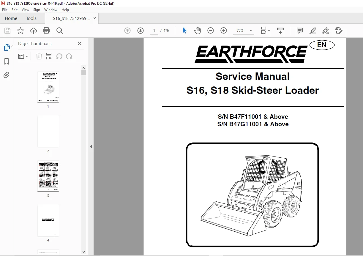
Bobcat EarthForce S16, S18 Skid-Steer Loader Service Manual 7312959 (04-19) – PDF DOWNLOAD
S/N B47F11001 & Above
S/N B47G11001 & Above
Description
Bobcat EarthForce S16, S18 Skid-Steer Loader Service Manual 7312959 (04-19) – PDF DOWNLOAD
FILE DETAILS:
Bobcat EarthForce S16, S18 Skid-Steer Loader Service Manual 7312959 (04-19) – PDF DOWNLOAD
Language : English
Pages : 476
Downloadable : Yes
File Type : PDF
IMAGES PREVIEW OF THE MANUAL:
DESCRIPTION:
Bobcat EarthForce S16, S18 Skid-Steer Loader Service Manual 7312959 (04-19) – PDF DOWNLOAD
S/N B47F11001 & Above
S/N B47G11001 & Above
FOREWORD:
This manual is for the EarthForce loader mechanic. It provides necessary servicing and adjustment procedures for the EarthForce loader and its component parts and systems. Refer to the Operation & Maintenance Manual for operating instructions, starting procedure, daily checks, etc.
SAFETY INSTRUCTIONS:
Safe Operation Needs A Qualified Operator
For an operator to be qualified, he or she must not use drugs or alcoholic drinks which impair alertness or coordination
while working. An operator who is taking prescription drugs must get medical advice to determine if he or she can safely operate a machine.
A Qualified Operator Must Do The Following:
Understand the Written Instructions, Rules and Regulations
• The written instructions from EarthForce include the Delivery Report, Operation & Maintenance Manual, Operator’s Handbook and machine signs (decals).
• Check the rules and regulations at your location. The rules may include an employer’s work safety
requirements. For driving on public roads, the machine must be equipped as stipulated by the local regulations authorising operation on public roads in your specific country. Regulations may identify a hazard such as a utility line.
Have Training with Actual Operation:
• Operator training must consist of a demonstration and verbal instruction. This training is given by your EarthForce dealer before the product is delivered.
• The new operator must start in an area without bystanders and use all the controls until he or she can operate the machine and attachment safely under all conditions of the work area. Always fasten seat belt before operating.
Know the Work Conditions:
• Know the weight of the materials being handled. Avoid exceeding the Rated Operating Capacity (ROC) of the machine. Material which is very dense will be heavier than the same volume of less dense material. Reduce the size of the load if handling dense material.
• The operator must know any prohibited uses or work areas, for example, he or she needs to know about excessive slopes.
• Know the location of any underground lines.
• Wear tight fitting clothing. Always wear safety glasses when doing maintenance or service. Safety glasses, respiratory equipment, hearing protection or Special Applications Kits are required for some work. See your EarthForce dealer about EarthForce Safety Equipment for your model.
TABLE OF CONTENTS:
Bobcat EarthForce S16, S18 Skid-Steer Loader Service Manual 7312959 (04-19) – PDF DOWNLOAD
MAINTENANCE SAFETY 3
CONTENTS 5
FOREWORD 7
FOREWORD 9
SAFETY INSTRUCTIONS 11
Safe Operation Is The Operator’s Responsibility 11
Safe Operation Needs A Qualified Operator 11
Avoid Silica Dust 12
FIRE PREVENTION 12
Maintenance 12
Operation 12
Electrical 12
Hydraulic System 12
Fueling 12
Starting 13
Welding And Grinding 13
Fire Extinguishers 13
SERIAL NUMBER LOCATIONS 14
Loader Serial Number 14
Engine Serial Number 14
DELIVERY REPORT 15
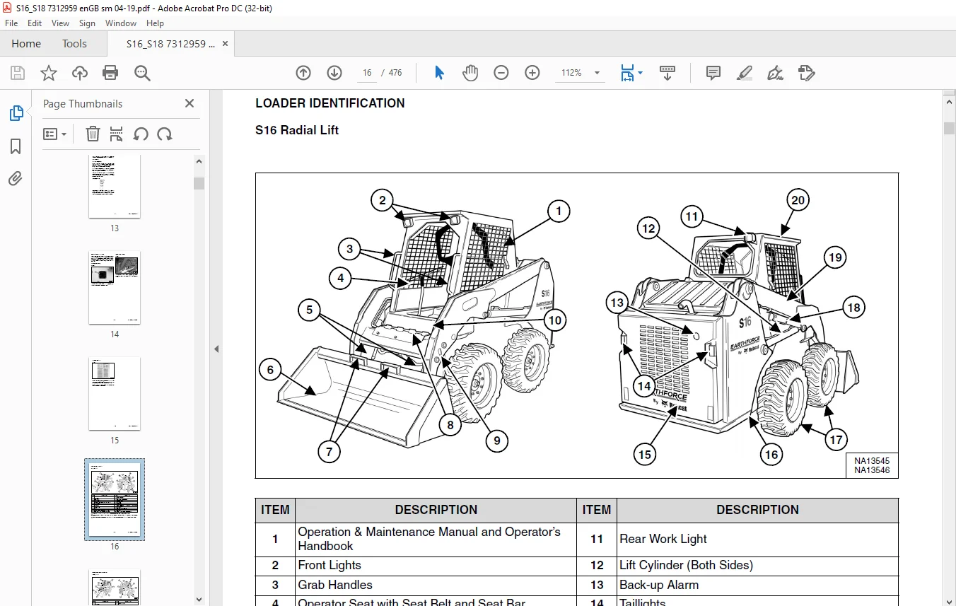
LOADER IDENTIFICATION 16
S16 Radial Lift 16
S18 Vertical Lift 17
SAFETY AND MAINTENANCE 19
LIFTING AND BLOCKING THE LOADER 21
Procedure 21
LIFT ARM SUPPORT DEVICE (S16 RADIAL PATH) 23
Description 23
Installing 24
Removing 25
LIFT ARM SUPPORT DEVICE (S18 VERTICAL PATH) 27
Description 27
Installing 28
Removing 29
OPERATOR CAB 31
Description 31
Raising 32
Lowering 33
Special Applications Kit 34
Special Applications Kit Inspection And Maintenance 34
TRANSPORTING THE LOADER ON A TRAILER 35
Loading And Unloading 35
Fastening 35
TOWING THE LOADER 37
Procedure 37
SERVICE SCHEDULE 39
Maintenance Intervals 39
AIR CLEANER SERVICE 41
Replacing Filter Elements 41
ENGINE COOLING SYSTEM 43
Cleaning 43
Checking And Adding Coolant 44
Removing And Replacing Coolant 45
FUEL SYSTEM 47
Fuel Specifications 47
Biodiesel Blend Fuel 48
Filling The Fuel Tank 49
Fuel Filters 50
Removing Air From The Fuel System 52
ENGINE LUBRICATION SYSTEM 53
Checking And Adding Engine Oil 53
Engine Oil Chart 53
Removing And Replacing Oil And Filter 54
HYDRAULIC / HYDROSTATIC SYSTEM 57
Checking And Adding Fluid 57
Hydraulic / Hydrostatic Fluid Chart 57
Removing And Replacing Hydraulic Fluid 58
Removing And Replacing Hydraulic / Hydrostatic Filter 60
Removing And Replacing Hydraulic Case Drain Filter 61
Replacing Reservoir Breather Cap 61
FINAL DRIVE TRANSMISSION (CHAINCASE) 63
Checking And Adding Fluid 63
Removing And Replacing Fluid 63
AUXILIARY CONTROL LOCKBOLT 65
Procedure 65
ATTACHMENT COUPLER 67
Inspection And Maintenance 67
LUBRICATING THE LOADER 69
Lubrication Locations (S16 Radial Path) 69
Lubrication Locations (S18 Vertical Path) 71
TYRE MAINTENANCE 75
Wheel Nuts 75
Rotating 75
Mounting 75
PIVOT PINS 77
Inspection And Maintenance 77
SEAT BAR RESTRAINT SYSTEM 79
Description 79
Inspection And Maintenance 80
LOADER STORAGE AND RETURN TO SERVICE 81
Storage 81
Return To Service 81
STOPPING THE ENGINE AND LEAVING THE LOADER 83
Procedure 83
EMERGENCY EXIT 85
Rear Window Removal 85
Front Door 85
SEAT BELT 87
Inspection And Maintenance 87
HYDRAULIC SYSTEM 89
HYDRAULIC / HYDROSTATIC SCHEMATICS 91
HYDRAULIC SYSTEM INFORMATION 93
Glossary Of Hydraulic / Hydrostatic Symbols 93
Troubleshooting Chart 97
CYLINDER (LIFT) 99
Testing (S16 Radial Path) 99
Removal And Installation (S16 Radial Path) 100
Testing (S18 Vertical Path) 102
Removal And Installation (S18 Vertical Path) 103
Parts Identification (S16 Radial Path) 105
Parts Identification (S18 Vertical Path) 106
Disassembly And Assembly 107
CYLINDER (TILT) 111
Testing 111
Removal And Installation 112
Parts Identification 114
Disassembly And Assembly 115
MAIN RELIEF VALVE 119
Description 119
Testing Without Auxiliaries 119
Testing With Auxiliaries 120
Adjusting 121
Removal And Installation 122
HYDRAULIC CONTROL VALVE 123
Description 123
Removal And Installation 124
Identification Chart 127
Disassembly And Assembly 128
Lift And Tilt Solenoid Removal And Installation 128
Port Check Valve 128
Main Relief Valve Removal And Installation 129
Port Relief Valve Removal And Installation 130
Lift Spool Removal And Installation 131
Tilt Spool Removal And Installation 134
Auxiliary Spool Removal And Installation 136
LIFT ARM BYPASS CONTROL VALVE 137
Description 137
Testing 137
Removal And Installation 137
Disassembly And Assembly 138
HYDRAULIC PUMP 139
Description 139
Direct Pump Testing 139
Removal And Installation 141
Hydraulic Pump Startup 143
Parts Identification 144
Disassembly And Assembly 145
HYDRAULIC / HYDROSTATIC FILTER 147
Description 147
Housing Removal And Installation 147
Hydrostatic Filter Housing Removal And Installation 148
HYDRAULIC FLUID RESERVOIR 149
Description 149
Removal And Installation 149
Hydraulic Fluid Screen 150
OIL COOLER 151
Description 151
Removal And Installation 151
LIFT ARM HYDRAULIC INTERLOCK VALVE 153
Description 153
Solenoid Removal And Installation 153
Solenoid Testing 154
Removal And Installation 154
Disassembly And Assembly 156
AUXILIARY HYDRAULIC INTERLOCK VALVE 157
Description 157
Solenoid Removal And Installation 157
Solenoid Testing 158
Removal And Installation 158
Disassembly And Assembly 160
HYDROSTATIC SYSTEM 161
HYDROSTATIC SYSTEM INFORMATION 163
Description 163
Troubleshooting 164
HYDROSTATIC DRIVE MOTOR 165
Description 165
Removal And Installation 165
Parts Identification 168
Disassembly And Assembly 169
HYDROSTATIC MOTOR CARRIER 175
Description 175
Shaft Seal Removal And Installation 176
Removal And Installation 178
Parts Identification 180
Disassembly 181
Assembly 183
CHARGE PRESSURE 187
Description 187
Testing 187
Sender Removal And Installation 188
HYDROSTATIC PUMP 189
Description 189
Removal And Installation 190
Parts Identification (Left Half) 192
Parts Identification (Right Half) 193
Disassembly 194
Assembly 202
DRIVE COUPLER 209
Description 209
Coupler Removal And Installation 209
DRIVE SYSTEM 211
BRAKE 213
Description 213
Disc Removal And Installation 213
DRIVE COMPONENTS 215
Description 215
Axle Seal Removal And Installation 216
Axle, Sprocket And Bearings Removal And Installation 218
Chain Removal And Installation 222
CHAINCASE 225
Description 225
Front Cover Removal And Installation 225
Center Cover Removal And Installation 226
Rear Cover Removal And Installation 227
MAINFRAME 229
SEAT BAR 231
Description 231
Inspection And Maintenance 231
Removal And Installation 232
Disassembly And Assembly 233
Compression Spring Disassembly And Assembly 234
OPERATOR CAB 235
Gas Spring Removal And Installation (S16 Radial Lift) 235
Gas Spring Removal And Installation (S18 Vertical Lift) 236
Gas Spring Bracket Disassembly And Assembly 237
Removal And Installation (S16 Radial Lift) 238
Removal And Installation (S18 Vertical Lift) 240
OPERATOR SEAT 243
Removal And Installation 243
Seat Belt Removal And Installation 243
ATTACHMENT COUPLER 245
Description 245
Removal And Installation 245
Lever And Wedge Disassembly And Assembly 247
LIFT ARMS 249
Removal And Installation (S16 Radial Lift) 249
Removal And Installation (S18 Vertical Lift) 251
Stabilizer Bar Removal And Installation (Vertical Lift Only) 254
Link Removal And Installation (Vertical Lift Only) 255
REAR GRILLE 257
Removing 257
Installing 257
REAR DOOR 259
Removal And Installation 259
FUEL TANK 261
Removal And Installation 261
CONTROL PEDALS AND LINKAGES 263
Description 263
Pedal Removal And Installation 263
Pedal (Adjusting) 264
Linkage Removal And Installation 264
CONTROL PANEL 267
Description 267
Control Panel Removal And Installation 267
CONTROL LEVERS 271
Description 271
Lever Removal And Installation 271
Linkage Removal And Installation 273
Pintle Arm Disassembly And Assembly 276
Linkage Neutral (Adjusting) 277
Linkage Travel (Adjusting) 281
WINDOW (REAR) 285
Removal 285
WINDOW (TOP) 287
Removal 287
Installation 288
ACCESS PANEL (INSIDE) 289
Removal And Installation (Left) 289
Removal And Installation (Right) 289
ELECTRICAL SYSTEM 291
ELECTRICAL SCHEMATICS 293
ELECTRICAL SYSTEM INFORMATION 299
Glossary Of Electrical Symbols 299
Cab Harness Connectors 302
Mainframe Harness Connectors (S16) 303
Mainframe Harness Connectors (S18) 304
Description 305
Troubleshooting 306
Fuse And Relay Location / Identification 307
Solenoid Testing 309
BATTERY 311
Removal And Installation 311
Battery Maintenance 312
Maintaining Battery Charge Level 312
Battery Service During Machine Storage 312
Battery Testing 313
Battery Charging 313
Using A Booster Battery (Jump Starting) 314
ALTERNATOR 315
Belt Adjustment 315
Belt Replacement 316
Charging System Inspection 317
Alternator Voltage Testing 318
Low Voltage Testing 318
High Voltage Testing 319
Removal And Installation 320
STARTER 321
Testing 321
Removal And Installation 321
INSTRUMENT PANEL IDENTIFICATION 323
Left Panel 323
Right Panel 323
Information Panel 324
Key Switch 324
Left And Right Removal And Installation 325
LIGHTS 327
Front Removal And Installation 327
Rear Removal And Installation 327
Cab Light Removal And Installation 327
INTERLOCK CONTROL SYSTEM 329
Inspecting The Interlock Control System (Engine STOPPED – Key ON) 329
Inspecting The Seat Bar Sensor (Engine RUNNING) 329
Inspecting The Traction Lock And Parking Brake (Engine RUNNING) 329
Inspecting The Lift Arm Bypass Control 329
Inspecting Deactivation Of The Auxiliary Hydraulics System 330
SEAT BAR RESTRAINT SYSTEM 331
Description 331
Inspection And Maintenance 332
Removal And Installation 333
TRACTION LOCK 335
Description 335
Troubleshooting 335
Removal And Installation 336
BACK-UP ALARM SYSTEM 339
Description 339
Inspection 339
Adjusting Switch Position 340
Troubleshooting 341
Alarm Removal And Installation 342
Switch Removal And Installation 342
ENGINE SERVICE 343
ENGINE INFORMATION 345
Description 345
Specifications 346
Torque Values 349
Troubleshooting 349
Engine Removal And Installation 351
Engine Mount Replacement 356
Compression – Testing 357
ENGINE SPEED CONTROL 359
Removal And Installation 359
MUFFLER 361
Removal And Installation 361
Muffler Hardware Tightening Sequence 361
AIR CLEANER 363
Housing Removal And Installation 363
ENGINE COOLING SYSTEM 365
Radiator / Oil Cooler Removal And Installation 365
Fan Removal And Installation 367
Water Pump Removal And Installation 368
Water Pump Disassembly And Assembly 368
Thermostat Housing Removal And Installation 369
Thermostat Testing 370
LUBRICATION SYSTEM 371
Oil Pan Removal And Installation 371
Relief Valve – Inspection 371
Oil Pump Removal And Installation 372
Oil Pump Inspection 372
Engine Oil Pressure – Testing 373
FUEL SYSTEM 375
Fuel Shutoff Solenoid – Testing 375
Fuel Shutoff Solenoid Removal And Installation 375
Fuel Injection Pump – Testing 376
Fuel Injection Pump Removal And Installation 377
Governor Disassembly And Assembly 381
Fuel Camshaft Removal And Installation 382
Fuel Injection Pump – Timing 382
Fuel Injector Removal And Installation 384
Fuel Injector Nozzle Pressure – Testing 385
Nozzle Spray Condition 386
Valve Seat Tightness 386
CYLINDER HEAD 387
Glow Plugs – Testing 387
Glow Plugs Removal And Installation 387
Valve Clearance Adjustment 388
Valve Timing – Inspecting 389
Cylinder Head Removal And Installation 390
Cylinder Head Disassembly And Assembly 393
Cylinder Head – Servicing 393
Cylinder Head Top Clearance 394
Valve Guide – Inspecting 394
Valve Guide Removal And Installation 395
Reconditioning The Valve And Valve Seat 395
Valve Spring 397
Valve Tappets 398
Rocker Arm And Shaft – Inspecting 399
Push Rod Alignment 399
CRANKSHAFT AND PISTONS 401
Piston And Connecting Rod Removal And Installation 401
Piston And Connecting Rod – Servicing 402
Cylinder Bore – Inspecting 405
Connecting Rod Alignment 405
Crankshaft Gear Removal And Installation 406
Crankshaft And Bearings Removal And Installation 406
Crankshaft And Bearings – Servicing 408
CAMSHAFT AND TIMING GEARS 413
Timing Gearcase Cover Removal And Installation 413
Timing Gears Backlash – Inspection 415
Idler Gear And Camshaft Removal And Installation 416
Camshaft – Servicing 417
Idler Gear And Shaft – Servicing 418
FLYWHEEL AND HOUSING 419
Flywheel Removal And Installation 419
Ring Gear Removal And Installation 419
Housing Removal And Installation 420
HEATER 421
HEATER SYSTEM 423
Description 423
REGULAR MAINTENANCE 425
Heater Coil 425
TROUBLESHOOTING 427
Electric System 427
Blower Motor Does Not Operate 427
Blower Motor Operates Normally, But Air Flow Is Insufficient 427
Blower Does Not Blow Warm Air 427
HEATER UNIT 429
Removal And Installation 429
HEATER COIL 431
Removal And Installation 431
HEATER FAN 433
Removal And Installation 433
HEATER VALVE 435
Removal And Installation 435
SPECIFICATIONS 437
(S16) LOADER SPECIFICATIONS 439
Machine Dimensions (S16) 439
Performance (S16) 440
(S18) LOADER SPECIFICATIONS 441
Machine Dimensions (S18) 441
Performance (S18) 442
(S16 & S18) LOADER SPECIFICATIONS 443
Engine 443
Drive System 444
Controls 444
Hydraulic System 444
Electrical System 445
Capacities 445
Tyres 445
TECHNICAL SERVICE GUIDE SPECIFICATIONS 447
Engine 447
Engine Torques 447
Cooling System 447
Loader Torques 448
Hydraulic / Hydrostatic System 448
Fuel Consumption 448
TORQUE SPECIFICATIONS FOR BOLTS 449
Torque For General SAE Bolts 449
Torque For General Metric Bolts 450
HYDRAULIC CONNECTION SPECIFICATIONS 451
O-ring Face Seal Connection 451
Straight Thread O-ring Fitting 452
Tubelines And Hoses 452
Flare Fitting 452
Port Seal Fitting 453
HYDRAULIC / HYDROSTATIC FLUID SPECIFICATIONS 455
Specifications 455
CONVERSIONS 457
Decimal And Millimeter Equivalent Chart 457
U S To Metric Conversion Chart 457
SERVICE TOOLS REQUIRED 459
Remote Start Tools 459
Hydraulic Tools 460
Mainframe And Drive Tools 463
Electrical Tools 466
Engine Tools 467
HVAC Tools 472
ALPHABETICAL INDEX 473
Need help? Contact: [email protected]
PLEASE NOTE:
- This is the SAME manual used by the dealers to troubleshoot any faults in your vehicle. This can be yours in 2 minutes after the payment is made.
- Contact us at [email protected] should you have any queries before your purchase or that you need any other service / repair / parts operators manual.
S.V