Bobcat Excavator 320 320L Service Manual 6901062 – PDF DOWNLOAD
$34.95
Bobcat Excavator 320 320L Service Manual 6901062 – PDF DOWNLOAD
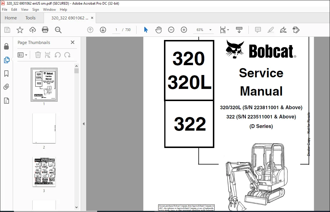
320/320L (S/N 223811001 & Above)
322 (S/N 223511001 & Above)
(D Series)
Description
Bobcat Excavator 320 320L Service Manual 6901062 – PDF DOWNLOAD
FILE DETAILS:
Bobcat Excavator 320 320L Service Manual 6901062 – PDF DOWNLOAD
Language : English
Pages : 730
Downloadable : Yes
File Type : PDF
Size:25.4 MB
DESCRIPTION:
Bobcat Excavator 320 320L Service Manual 6901062 – PDF DOWNLOAD
FOREWORD
This manual is for the Bobcat hydraulic excavator mechanic. It provides necessary servicing an d
adjustment procedures for the hydraulic excavator and its component parts and systems. Refer to the
Operation & Maintenance Manual for operating instructions, starting procedure, daily checks, etc
A general inspection of the following items must be made after the hydraulic excavator has had service
or repair:
• The Delivery Report is used to assure that complete instructions have been given to the new owner and that the machine
is in safe operating condition.
• The Operation & Maintenance Manual delivered with the excavator gives operating information as well as routin e
maintenance and service procedures. It is a part of the excavator and must stay with the machine when it is sol d.
Replacement Operation & Maintenance Manuals can be ordered from your Bobcat Excavator dealer.
• The excavator has machine signs (decals) which instruct on the safe operation and care. The signs and their locations
are shown in the Operation & Maintenance Manual. Replacement signs are available from your Bobcat Excavator dealer.
Safety Alert Symbol: This Safety Symbol is used for important safety messages. When you see this symbol follow
the safety message to avoid personal injury or death.
• The Bobcat Hydraulic Excavator has a plastic Operator’s Handbook fastened to the operator cab. It’s brief instructions
are convenient to the operator. The handbook is available from your dealer in an English, French, German, Dutch, Italian,
Spanish, Portugese, Finnish, Danish, and Swedish editions.
• The CIMA Safety Manual delivered with the excavator gives information for safe operating and standard signals.
• The Service Manual and Parts Manual are available from your dealer for use by mechanics to do shop–type service and
repair work.
• The Bobcat compact Excavator Operator Training Course is available through your local dealer. This course is intended
to provide rules and practices of correct operation of the Hydraulic Excavator.
TABLE OF CONTENTS:
Bobcat Excavator 320 320L Service Manual 6901062 – PDF DOWNLOAD
MAINTENANCE SAFETY 3
ALPHABETICAL INDEX 5
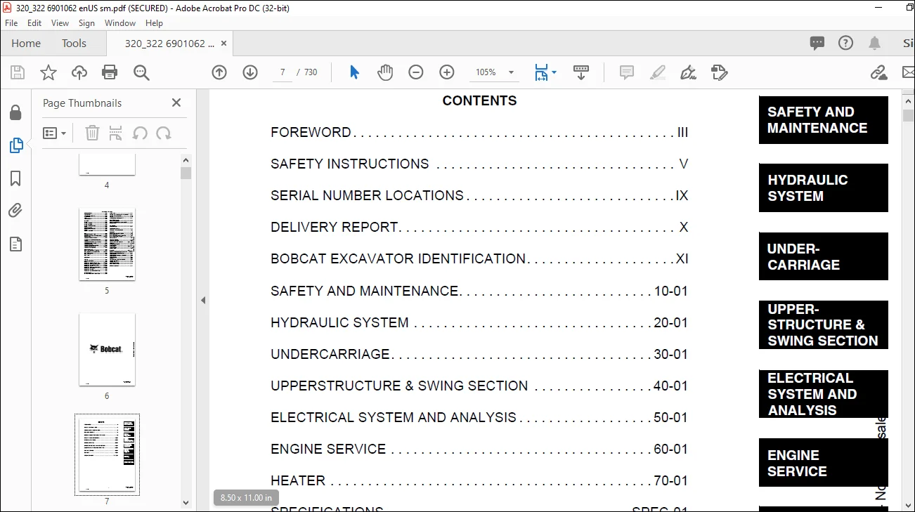
CONTENTS 7
FOREWORD 9
SAFETY INSTRUCTIONS 11
Fire Prevention 13
SERIAL NUMBER LOCATIONS 15
Excavator Serial Number 15
Engine Serial Number 15
DELIVERY REPORT 16
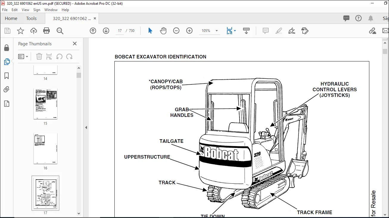
BOBCAT EXCAVATOR IDENTIFICATION 17
SAFETY AND MAINTENANCE 19
LIFTING AND BLOCKING THE EXCAVATOR 21
Procedure 21
SWING LOCK 23
Operation 23
LIFTING THE EXCAVATOR 25
3-Point Lift Procedure 25
OPERATOR CAB 27
Emergency Exit 27
Cab Door 27
Front Window 27
TRANSPORTING THE EXCAVATOR 29
TAILGATE 31
Opening And Closing The Tailgate (S/N 223513558 & Below And 223812078 & Below) 31
Adjusting The Tailgate Latch (S/N 223513558 & Below And 223812078 & Below) 31
Opening And Closing The Tailgate (S/N 223513559 & Above And 223812079 & Above) 32
Adjusting The Tailgate Latch (S/N 223513559 & Above And 223812079 & Above) 32
Adjusting The Bumper 33
SERVICE SCHEDULE 35
Chart 35
AIR CLEANER SERVICE 37
Daily Check 37
Replacing The Filters 37
HEATER AIR FILTERS 39
Recirculation Filter 39
Fresh Air Filter 39
ENGINE COOLING SYSTEM 41
Cleaning The Cooling System 41
Checking Coolant Level 41
Replacing The Coolant 42
FUEL SYSTEM 45
Fuel Specifications 45
Filling The Fuel Tank 45
Removing Water From The Fuel Filter 46
Replacing The Fuel Filter 46
Draining The Fuel Tank 46
Removing Air From The Fuel System 47
ENGINE LUBRICATION SYSTEM 49
Checking Engine Oil 49
Replacing Oil And Filter 49
HYDRAULIC SYSTEM 51
Checking And Adding Fluid 51
Diagnostic Couplers 51
Replacing The Hydraulic Filter 52
Replacing The Hydraulic Fluid (S/N 223512346 & Below and 223814376 & Below) 52
Replacing The Hydraulic Fluid (S/N 223512347 & Above and 22384377 & Above) 54
LUBRICATING THE EXCAVATOR 57
FINAL DRIVE CASE 61
Checking Oil Level 61
Draining Final Drive Case 61
SPARK ARRESTOR MUFFLER 63
HYDRAULIC SYSTEM 65
HYDRAULIC/HYDROSTATIC SCHEMATICS 71
HYDRAULIC SYSTEM INFORMATION 75
Troubleshooting Chart 75
BOOM CYLINDER 79
Checking The Boom Cylinder 79
Removal and Installation 81
Parts Identification 83
Disassembly 84
Assembly 85
ARM CYLINDER 89
Checking The Arm Cylinder 89
Removal and Installation 90
Parts Identification 92
Disassembly 93
Assembly 95
BOOM SWING CYLINDER 99
Checking The Boom Swing Cylinder 99
Removal and Installation 100
Parts Identification 104
Disassembly 105
Assembly 107
BUCKET CYLINDER 111
Checking The Bucket Cylinder 111
Removal and Installation 112
Parts Identification 114
Disassembly 115
Assembly 117
BLADE CYLINDER 121
Checking The Blade Cylinder 121
Removal and Installation 124
Parts Identification 126
Disassembly 127
Assembly 128
TRACK FRAME EXPANSION CYLINDER 133
Checking The Track Frame Expansion Cylinder 133
Removal And Installation 134
Parts Identification 138
Disassembly 139
Assembly 140
MAIN RELIEF VALVE 145
Testing And Adjusting The Main Relief Valve 145
PORT RELIEF VALVES 147
Testing And Adjusting The Port Relief Valve Pressure (S/N 223512064 & Below and 223813552 & Below) 147
Testing And Adjusting The Port Relief Valve Pressure (S/N 223512065 & Above and 223813553 & Above) 148
CROSSPORT RELIEF VALVES 151
Testing And Adjusting The Crossport Relief Valve 151
PRESSURE REDUCING VALVE 153
Testing And Adjusting The Pressure Reducing Valve 153
HYDRAULIC CONTROL VALVE ASSEMBLY (S/N 223512346 & BELOW AND 223814376 & BELOW) 155
Description 155
Removal and Installation 155
Control Valve Identification [Figure 20-40-13]: 159
Disassembly 160
Auxiliary Valve Section Disassembly And Assembly 161
Blade Valve Section Disassembly And Assembly 163
Swing Valve Section Disassembly And Assembly 165
Left Travel Valve Section Disassembly And Assembly 167
Boom Valve Section Disassembly And Assembly 169
Bucket Valve Section Disassembly And Assembly 172
Build Up Valve 174
Arm Valve Section Disassembly And Assembly 174
Boom Swing Valve Section Disassembly And Assembly 177
Right Travel Valve Section Disassembly And Assembly 180
Assembly 182
HYDRAULIC CONTROL VALVE ASSEMBLY (S/N 223512347 & ABOVE AND 223814377 & ABOVE) 189
Description 189
Removal and Installation 189
Control Valve Identification 193
Disassembly 194
Auxiliary Valve Section Disassembly And Assembly 195
Blade Valve Section Disassembly And Assembly 199
Swing Valve Section Disassembly And Assembly 202
Left Travel Valve Section Disassembly and Assembly 206
Boom Valve Section Disassembly and Assembly 209
Bucket Valve Section Disassembly and Assembly 213
Arm Valve Section Disassembly and Assembly 218
Boom Swing Valve Section Disassembly And Assembly 222
Right Travel Valve Section Disassembly And Assembly 226
Assembly 231
GEAR PUMP 237
Testing The Hydraulic Pump (S/N 223512064 & Below and 223813552 & Below) 237
Testing The Hydraulic Pump (S/N 223512065 & Above and 223813553 & Above) 238
Removal And Installation 239
Coupler Removal And Installation 241
Parts Identification 242
Disassembly 243
Assembly 245
MANIFOLD ASSEMBLY/ACCUMULATOR 249
Manifold (Description) 249
Removal and Installation 250
MANIFOLD ASSEMBLY (S/N 223513430 & BELOW AND 223811991 & BELOW) 253
Parts Identification 253
Disassembly 254
Assembly 261
MANIFOLD ASSEMBLY (S/N 223513431 & ABOVE AND 223811992 & ABOVE) 269
Parts Identification 269
Disassembly 270
Assembly 279
TRAVEL MOTOR 289
Removal and Installation 289
Parts Identification 290
Disassembly 291
Assembly 298
SWIVEL JOINT 307
Removal And Installation 307
Parts Identification 320 310
Parts Identification 322 311
Disassembly 312
Assembly 316
SWING MOTOR 321
Removal and Installation 321
Parts Identification 322
Disassembly 323
Assembly 329
Crossport Relief Valve Parts Identification 338
Crossport Relief Valve Disassembly 339
Crossport Relief Valve Assembly 340
CONTROL PATTERN SELECTOR VALVE 343
Removal And Installation 343
Parts Identification 345
Disassembly 346
Assembly 347
RIGHT CONTROL LEVER (JOYSTICK) (S/N 223512346 & BELOW AND S/N 223814376 & BELOW) 349
Testing 349
Removal And Installation 350
Parts Identification 353
Disassembly 354
Assembly 360
LEFT CONTROL LEVER (JOYSTICK) (S/N 223512346 & BELOW AND S/N 23814376 & BELOW) 366
Testing 366
Removal And Installation 367
Parts Identification 370
Disassembly 371
Assembly 375
RIGHT CONTROL LEVER (JOYSTICK) (S/N 223512347 & ABOVE AND 223814377 & ABOVE) 381
Testing 381
Removal And Installation 382
Parts Identification 384
Disassembly 385
Assembly 389
Handle Removal And Installation 394
LEFT CONTROL LEVER (JOYSTICK) (S/N 223512347 & ABOVE AND 223814377 & ABOVE) 395
Testing 395
Removal And Installation 396
Parts Identification 398
Disassembly And Assembly 399
Handle Removal And Installation 399
HYDRAULIC FILTER 403
Removal And Installation (S/N 223513017 & Below And 223811795 & Below) 403
Removal And Installation (S/N 223513018 & Above And 223811796 & Above 404
HYDRAULIC RESERVOIR 405
Removal and Installation 405
OIL COOLER 407
Removal And Installation 407
ACCUMULATORS (S/N 223811055-223811259 AND 223511138-223511609) 409
Removal And Installation 409
BLADE 413
Extension Removal And Installation 413
Blade Removal And Installation 413
TRACKS 415
Track Lug Height 415
Adjustment 416
Removal And Installation 418
Track Damage Identification And Causes 418
TRACK FRAME 419
Disassembly And Assembly 419
Removal And Installation Of Expandable Track Frame (322 Only) 422
TRACK IDLER 423
Parts Identification (S/N 223512998 & Below And 2238117779 & Below) 423
Disassembly (S/N 223512998 & Below And 2238117779 & Below) 424
Assembly (S/N 223512998 & Below And 223811779 & Below) 427
Parts Identification (S/N 223512999 & Above And 223811780 & Above) 431
Disassembly (S/N 223512999 & Above And 223811780 & Above) 432
Assembly (S/N 223512999 & Above And 223811780 & Above) 434
TRACK ROLLER 437
Parts Identification (S/N 223511788 & Below And 223811359 & Below) 437
Disassembly (S/N 223511788 & Below And 223811359 & Below) 438
Assembly (S/N 223511788 & Below And 223811359 & Below) 440
Parts Identification (S/N 223511789 & Above And 223811360 & Above) 444
Disassembly (S/N 223511789 & Above And 223811360 & Above) 445
Assembly (S/N 223511789 & Above And 223811360 & Above) 447
TRACK DAMAGE IDENTIFICATION 450
Cutting Of The Steel Cords 450
Causes Of The Damage 450
Abrasion Of Embedded Metals 451
Separation Of Embedded Metals Due To External Forces 452
Separation Of Embedded Metals Due To Corrosion 454
Cuts On The Lug Side 455
Cracks On The Lug Side Rubber Due To Fatigue 456
Lug Abrasion 457
Cracks And Cuts On The Lug Side Rubber At The Edges Of The Embedded Metals 458
Abrasion Of The Track Roller Side Rubber Surface 459
Cuts On The Edges Of The Track Roller Side 460
SWING CIRCLE GEAR 463
Removal and Installation 463
UPPERSTRUCTURE & SWING SECTION 465
UPPERSTRUCTURE 469
Removal 469
Installation 471
ROPS CANOPY 473
Removal And Installation 473
CAB 477
Removal And Installation 477
Door Removal And Installation 482
Front Window Removal And Installation 483
Lower Front Window Removal And Installation 485
Right Side Rear Sliding Window Removal And Installation (S/N 223512957 & Below and 223811744 & Below) 486
Right Side Front Sliding Window Removal And Installation (S/N 223512957 & Below And 223811744 & Below) 488
Right Side Rear Sliding Window Removal And Installation (S/N 223512958 & Above And 223811745 & Above) 489
Right Side Front Sliding Window Removal And Installation (S/N 2235129584 & Above And 223811745 & Above) 490
Right Side Front And Rear Sliding Window Weather Strip Removal And Installation 491
Right Side Front And Rear Sliding Window Wiper Strip Removal And Installation 491
Right Side Panel And Window Assembly Removal And Installation 492
Door, Left Side, Rear & Upper Front Window Removal & Installation 496
SEAT AND SEAT MOUNT 499
Removal And Installation (S/N 223512842 & Below And 223811738 & Below) 499
Removal And Installation (S/N 223512932 & Above and 223811739 & Above) 500
RIGHT CONSOLE 501
Console Cover Removal And Installation (Cab Models 320L, 320, 322 & ROPS Canopy Model 320L) 501
Console Cover Removal And Installation (ROPS Canopy Models 320 & 322) 504
Gas Spring Removal And Installation (ROPS Canopy Models 320 & 322) 507
Lock Lever Removal And Installation (ROPS Canopy Models 320 & 322) 508
Adjustment (ROPS Canopy Models 320 & 322) 510
Latch Hook Removal And Installation (ROPS Canopy Models 320 & 322) 510
Latch Hook Disassembly And Assembly (ROPS Canopy Models 320 & 322) 511
Cab Models (320L, 320 & 322, And ROPS Canopy Model 320L) 512
Upper Console Removal And Installation 513
Console Base Removal And Installation 514
LEFT CONSOLE 517
Console Cover Removal And Installation 517
Gas Spring Removal And Installation 518
Lock Lever Removal And Installation 519
Adjustment 521
Latch Hook Removal And Installation 522
Upper Console Removal And Installation 523
Console Base Removal And Installation 524
ENGINE SPEED CONTROL 527
Removal and Installation 527
Engine Speed Control Cable Removal and Installation 528
BLADE CONTROL 531
Removal and Installation 531
Disassembly And Assembly 533
SWING LOCK 535
Removal and Installation 535
RIGHT PEDAL AND LINKAGE 537
Right Pedal Removal And Installation 537
Right Pedal Disassembly And Assembly 537
Linkage Disassembly And Assembly 538
TRAVEL CONTROLS 541
Right Travel Control Removal And Installation 541
Right Travel Control Disassembly And Assembly 541
Left Travel Control Removal And Installation 542
Left Travel Control Disassembly And Assembly 542
LEFT PEDAL 543
Removal And Installation 543
Disassembly And Assembly 543
CONTROL LINKAGE ASSEMBLY 545
Removal and Installation 545
Left Pedal Linkage Disassembly And Assembly 546
Right Travel Control Linkage Disassembly And Assembly 547
Left Travel Control Linkage Disassembly And Assembly 547
Linkage Rod Removal And Installation 548
FLOOR MAT AND FLOOR PANELS 551
Removal and Installation 551
BLADE EXTENSION TRAY 553
Removal And Installation 553
FUEL TANK 555
Removal and Installation 555
HORN 557
Removal and Installation 557
SWING FRAME 559
Removal And Installation 559
Bushing Replacement 561
Swing Frame Bushing Removal 561
Swing Frame Bushing Installation 562
Boom Pivot Bushing Removal And Installation (S/N 223511699 & Above And 223812931 & Above) 563
BOOM 565
Removal And Installation 565
Boom Bushing Removal And Installation 567
ARM 569
Removal And Installation 569
Arm To Boom Bushing Removal And Installation 570
Arm To Bucket And Bucket Link Bushing Removal And Installation 570
BUCKET 573
Removal and Installation 573
Installation 574
TAILGATE 575
Removal And Installation 575
Tailgate Release Bracket Removal And Installation (S/N 223513558 & Below And 223812078 & Below) 576
Tailgate Release Rod Removal And Installation (S/N 223513558 & Below And 223812078 & Below) 577
Tailgate Latch Removal And Installation (S/N 223513558 & Below And 223812078 & Below) 577
Tailgate Latch Removal And Installation (S/N 223513559 & Above And 223812079 & Above) 578
ELECTRICAL SYSTEM AND ANALYSIS 579
ELECTRICAL SCHEMATICS 581
ELECTRICAL SYSTEM INFORMATION 583
Troubleshooting Chart 583
Description 584
Fuses 584
Relays And Diodes 585
BATTERY 587
Servicing 587
Removing And Installing 588
Using A Booster Battery (Jump Starting) 589
ALTERNATOR 591
Adjusting The Alternator Belt (S/N 223512942 & Below And 223811738 & Below) 591
Adjusting The Alternator Belt (S/N 223512943 & Above And 223811739 & Above) 591
Description 593
Tests 593
Alternator Output Test 593
Full Field Test 594
Alternator Regulator Test 594
Alternator Regulator Test With Voltmeter 595
Removal And Installation (S/N 223512842 & Below And 223811738 & Below) 595
Removal And Installation (S/N 223512943 & Above and 223811739 & Above) 597
Disassembly And Assembly 599
STARTER 601
Removal And Installation 601
Disassembly And Assembly 602
Cleaning and Inspection 602
LIGHTS 603
Upper Structure Light Removal And Installation (S/N 223513060 & Below And 223811816 & Below) 603
Upper Structure Light Disassembly And Assembly (S/N 223513060 & Below And 223811816 & Below) 603
Upper Structure Light Removal And Installation (S/N 223513061 & Above And 223811817 & Above) 604
Upper Structure Light Disassembly And Assembly (S/N 223513061 & Above And 223811817 & Above) 605
Boom Light Removal And Installation (S/N 223512224 & Below And 223811529 & Below) 605
Boom Light Removal And Installation (S/N 223512225 & Above And 223811530 & Above) 606
Boom Light Disassembly And Assembly 606
Light Switch Removal And Installation 607
MICROSWITCH 609
Adjustment 609
Testing 610
Removal And Installation 610
TWO-SPEED SWITCH 611
Removal And Installation 611
FUEL LEVEL SENDER 613
Removal and Installation 613
Testing 613
ENGINE SERVICE 615
TROUBLESHOOTING 617
Chart 617
SPARK ARRESTOR MUFFLER 619
Removal And Installation 619
AIR CLEANER 621
Removal And Installation 621
RADIATOR 623
Removal And Installation 623
ENGINE COMPONENTS AND TESTING 629
Valve Clearance Adjustment 629
Engine Compression Checking 629
Fuel Shut-off Solenoid Removal And Installation 630
Fuel Shut-Off Timer Removal And Installation 630
Fuel Injection Pump Check 631
Fuel Injection Pump Removal And Installation 632
Fuel Injection Pump Timing 633
Fuel Injector Removal And Installation 635
Fuel Injector Checking 636
Glow Plug Removal And Installation 638
Glow Plug Checking 639
ENGINE 641
Removal and Installation 641
ENGINE FLYWHEEL (EARLY MODELS) 649
Removal And Installation 649
Hydraulic Pump Coupler 651
Flywheel Ring Gear 651
RECONDITIONING THE ENGINE 653
Cylinder Head Removal And Installation 653
Cylinder Head Disassembly And Assembly 655
Cylinder Head, Servicing 656
Cylinder Head Top Clearance 657
Valve Guide, Checking 658
Valve And Valve Seat Reconditioning 660
Valve Spring 661
Rocker Arm And Shaft, Checking 662
Timing Gearcase Cover Removal And Installation 663
Idler Gear And Camshaft Removal And Installation 665
Idler Gear and Shaft, Servicing 667
Timing Gears Checking Backlash 668
Fuel Camshaft Removal And Installation 668
Fuel Camshaft Governor 669
Crankshaft Gear Removal And Installation 669
Oil Pump Removal And Installation 670
Oil Pump, Service 670
Engine Oil Pressure, Checking 671
Relief Valve 672
Piston And Connecting Rod Removal And Installation 673
Piston And Connecting Rod, Servicing 676
Connecting Rod Alignment 678
Crankshaft And Bearings Removal And Installation 679
Crankshaft And Bearings, Servicing 681
Cylinder Bore, Checking 683
Water Pump Removal And Installation 683
Water Pump Disassembly And Assembly 683
HEATER 685
HEATER 687
Removal And Installation 687
SPECIFICATIONS 689
HYDRAULIC EXCAVATOR SPECIFICATIONS 691
Machine Dimensions 691
Performance 693
Engine 693
Controls 693
Drive System 693
Hydraulic System 694
Electrical System 694
Instrumentation 694
ENGINE SPECIFICATIONS 695
Engine 695
Fuel Injector Nozzles 695
Fuel Injection Pump 695
Cylinder Head 695
Valves 695
Valve Springs 695
Rocker Arms 696
Camshaft 696
Cylinders 696
Piston Rings 696
Pistons 697
Crankshaft 697
Oil Pump 697
Thermostat 698
Engine Bolt Torque 698
Re-Grinding The Crankshaft 699
TORQUE SPECIFICATIONS FOR BOLTS 701
Torque for General SAE Bolts 701
Torque For General Metric Bolts 702
HYDRAULIC CONNECTION SPECIFICATIONS 703
O-Ring Face Seal Connection 703
Straight Thread O-ring Fitting 703
Tubelines And Hoses 703
Flare Fitting 703
O-Ring Flare Fitting 704
Port Seal Fitting 706
HYDRAULIC FLUID SPECIFICATIONS 707
Specifications 707
FUEL, COOLANT AND LUBRICANTS 709
Chart 709
CONVERSIONS 711
Decimal And Millimeter Equivalents 711
U S To Metric Conversion 712
SMR 713
320/322-1 713
320/322-2 715
320/322-3 717
320/322-4 719
320/322-5 721
320/322-6 723
320/322-7 725
320/322-8 727
320/322-9 729
IMAGES PREVIEW OF THE MANUAL:
Questions? Email us: [email protected]
https://vimeo.com/840458150?share=copy
PLEASE NOTE:
- This is the SAME exact manual used by your dealers to fix your vehicle.
- The same can be yours in the next 2-3 mins as you will be directed to the download page immediately after paying for the manual.
- Any queries / doubts regarding your purchase, please feel free to contact [email protected]
S.M


