Bobcat Excavator 331 Service Manual 6724222 (6-12) – PDF DOWNLOAD
$30.95
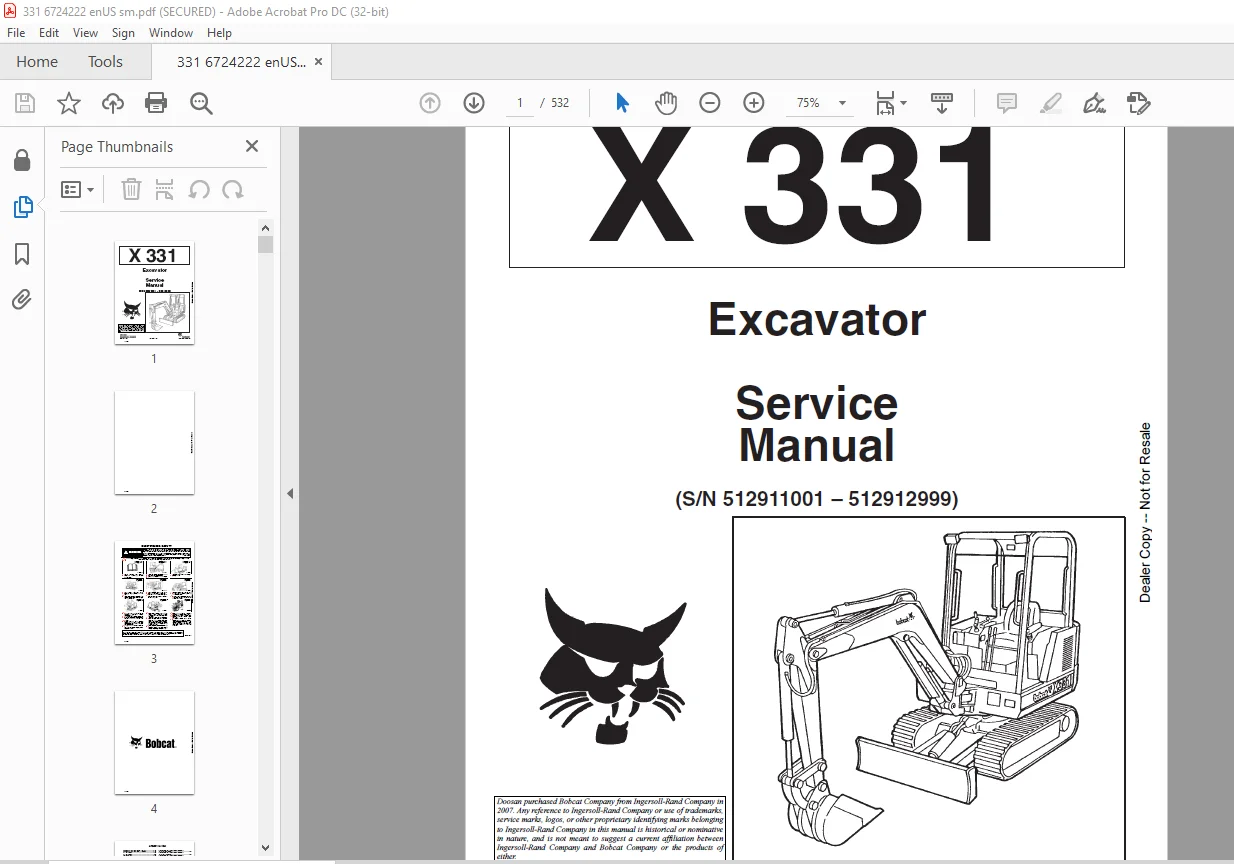
Bobcat Excavator 331 Service Manual 6724222 (6-12) – PDF DOWNLOAD
(S/N 512911001 – 512912999)
Description
Bobcat Excavator 331 Service Manual 6724222 (6-12) – PDF DOWNLOAD
FILE DETAILS:
Bobcat Excavator 331 Service Manual 6724222 (6-12) – PDF DOWNLOAD
Language : English
Pages : 532
Downloadable : Yes
File Type : PDF
Size:13.6 MB
DESCRIPTION:
Bobcat Excavator 331 Service Manual 6724222 (6-12) – PDF DOWNLOAD
FOREWORD
This manual is for the Bobcat excavator mechanic. It provides necessary servicing and adjustment procedures for the Bobcat excavator and its component parts and systems. Refer to the Operation & Maintenance Manual for operating instructions, starting procedure, daily checks, etc.
SAFETY INSTRUCTIONS
Instructions are necessary before operating or servicing machine. Read and understand the Operation & Maintenance Manual, Operator’s Handbook and signs (decals) on machine. Follow warnings and instructions in the manuals when making repairs, adjustments or servicing. Check for correct function after adjustments, repairs or service. Untrained operators and failure to follow instructions can cause injury or death.
The following publications provide information on the safe use and maintenance of the Bobcat machine and attachments
TABLE OF CONTENTS:
Bobcat Excavator 331 Service Manual 6724222 (6-12) – PDF DOWNLOAD
MAINTENANCE SAFETY 3
ALPHABETICAL INDEX 5
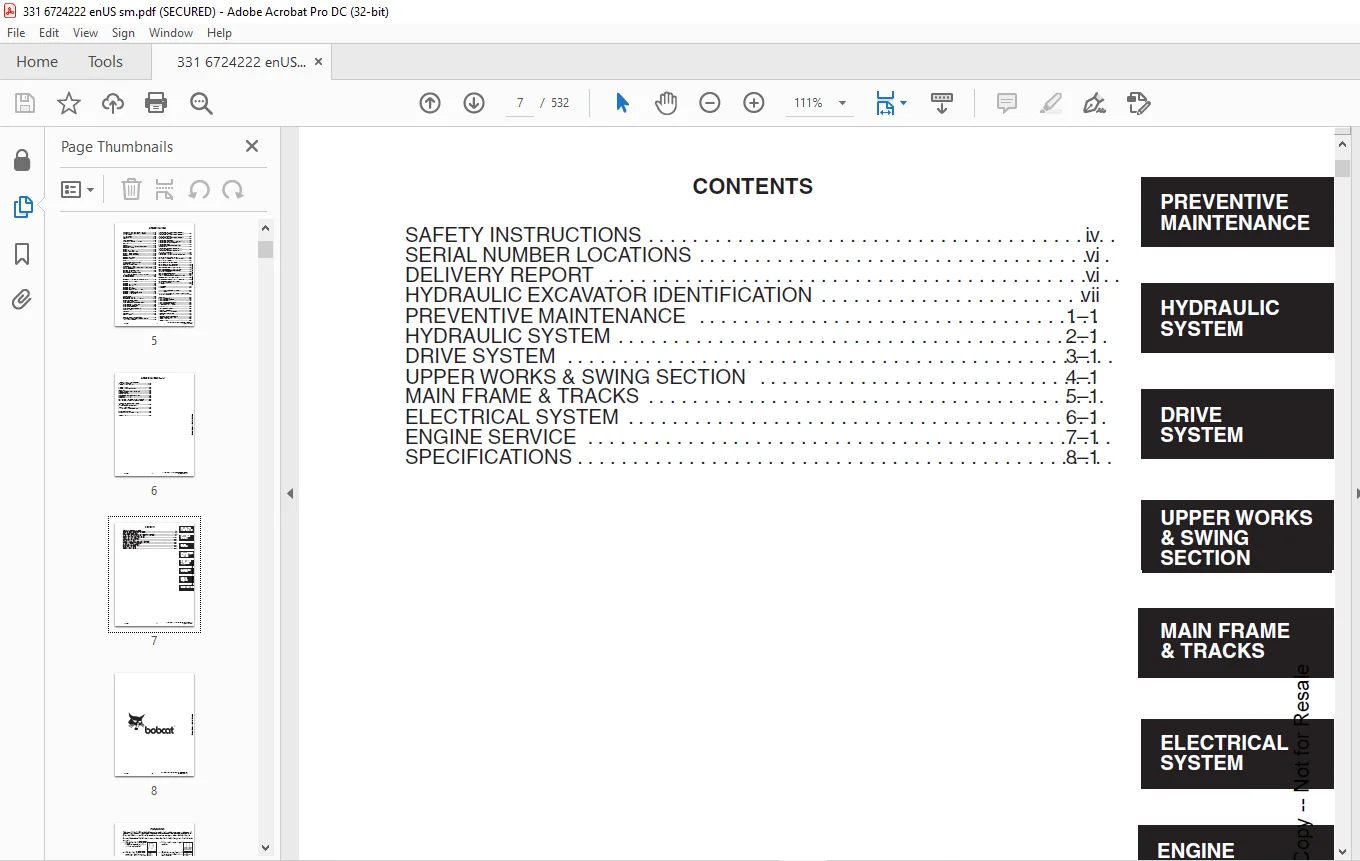
CONTENTS 7
FOREWORD 9
SAFETY INSTRUCTIONS 11
SERIAL NUMBER LOCATIONS 13
HYDRAULIC EXCAVATOR SERIAL NUMBER 13
ENGINE SERIAL NUMBER 13
DELIVERY REPORT 13
HYDRAULIC EXCAVATOR IDENTIFICATION 14
MACHINE SIGNS TRANSLATIONS (DECALS) 15
PREVENTIVE MAINTENANCE 17
SERVICE SCHEDULE (S/N 11001–11999) 19
SERVICE SCHEDULE (S/N 12001 & Above) 20
PREVENTIVE MAINTENANCE 21
LIFTING AND BLOCKING THE EXCAVATOR 21
Procedure 21
TRANSPORTING THE EXCAVATOR 22
Procedure 22
ENGINE COVER 23
Opening the Cover 23
AIR CLEANER 23
Servicing the Air Cleaner (S/N 11001–11999) 23
Servicing the Air Cleaner (S/N 12001–12999) 24
Servicing the Air Cleaner (S/N 13001 & Above) 26
FUEL SYSTEM 27
Fuel Specification 27
Filling the Fuel Tank 27
Fuel System Service 28
Fuel Filter 28
Removing Air from the Fuel System 28
ENGINE LUBRICATION SYSTEM 29
Checking Engine Oil 29
Replacing Oil and Filter 29
COOLING SYSTEM 30
Coolant Level 30
Ethylene Glycol 30
Propylene Glycol 30
Coolant Replacement 30
HYDRAULIC SYSTEM 31
Checking and Adding Fluid 31
Replacing the Hydraulic Filter (S/N 11001–11999) 31
Replacing the Hydraulic Filter (S/N 12001 & Above) 32
Return Line Filter Service (S/N 12240 & Above) 32
Hydraulic Reservoir 32
Diagnostic Couplers 32
USING A BOOSTER BATTERY (Jump Starting) 33
Procedure (S/N 11001–11999) 33
Procedure (S/N 12001 & Above) 34
SPARK ARRESTOR MUFFLER 35
Cleaning Spark Arrestor Muffler (S/N 11001–11999) 35
Cleaning Spark Arrestor Muffler (S/N 12001 & Above) 36
LUBRICATION OF THE EXCAVATOR 37
Procedure (S/N 11001 – 11999) 37
Procedure (S/N 12001 & Above) 40
FINAL DRIVE CASE 42
Checking Oil Level 42
Draining Final Drive Case 42
HEATER AIR FILTER SERVICE 42
HYDRAULIC SECTION 43
HYDRAULIC SCHEMATICS 47
HYDRAULIC SYSTEM TROUBLESHOOTING 79
HYDRAULIC SERVICE INFORMATION (S/N11001–12999) 84
Description 84
MAIN RELIEF VALVES (S/N 11001–12999) 84
Description 84
Checking Dual Pressure Relief Valves 85
Checking Single Pressure Relief Valve 86
Dual Pressure Relief Valve Adjustment (6–Spool Valve) 87
Single Pressure Relief Valve Adjustment (3–Spool Valve) 90
HYDRAULIC SERVICE INFORMATION (S/N 13001 &Above) 91
Description 91
MAIN RELIEF VALVE (Adjustable) (S/N 13001 & Above) 91
Checking the Main Relief Valves 91
Testing the Blade, Boom Swing, Arm and Boost Circuit Relief Valves 91
Testing the 4050 PSI (27925 kPa) Circuit Relief 92
Testing the Auxiliary and Bucket Circuit Relief Valve 93
Testing the Left Hand Travel Circuit Relief Valve 94
Testing the Right Hand Travel Circuit Relief Valve 95
Testing the Boom Circuit Relief Valve 96
HYDRAULIC PUMP 97
Checking the Hydraulic Pump 97
Removal and Installation 98
Parts Identification 99
Disassembly 100
Assembly 102
HYDRAULIC CONTROL VALVE (6–Spool) (S/N 12999 & Below) 105
Removal and Installation 105
Parts Identification 106
Disassembly 107
Assembly 107
Right Hand Travel Section Disassembly and Assembly 108
Boom, Bucket and Arm Section Disassembly and Assembly 111
Auxiliary Section Disassembly and Assembly 114
Left Hand Travel Section Disassembly and Assembly 116
End Cover Disassembly and Assembly 119
HYDRAULIC CONTROL VALVE (3–Spool) (S/N 12999 & Below) 121
Description 121
Removal and Installation 121
Parts Identification 122
Disassembly 123
Assembly 123
Housing Swing Section Disassembly and Assembly 124
Blade and Boom Swing Section Disassembly and Assembly 126
End Cover Disassembly and Assembly 129
HYDRAULIC CONTROL VALVE (5–Spool) HUSCO VALVE (S/N 13001 & Above) 131
Left Travel, Right Travel, Boom, Bucket and Auxiliary 131
Removal and Installation 131
Parts Identification 132
Disassembly 133
Outlet Sections Disassembly 134
Outlet Sections Assembly 134
Mid Inlet Section Disassembly 134
Mid Inlet Section Assembly 134
Left Travel, Right Travel and Auxiliary Disassembly 135
Left Travel, Right Travel and Auxiliary Assembly 137
Boom and Bucket Disassembly 139
Boom and Bucket Assembly 141
Assembly 143
PORT RELIEF VALVES AND MAIN RELIEF VALVES (S/N 13001 & Above) 144
Parts Identification 144
Port Relief Valve Pressure Setting 145
Disassembly 145
Assembly 146
MAIN RELIEF VALVES (Adjustable) (S/N 13001 & Above) 147
Parts Identification 147
Assembly 148
Disassembly 149
Assembly 149
Adjusting the Main Relief Valves 150
HYDRAULIC CONTROL VALVE (5–Spool) HUSCO VALVE (S/N 13001 & Above) 151
Boost, Arm, Boom Swing, Blade and Swing Section 151
Description 151
Removal and Installation 151
Parts Identification 152
Disassembly 153
Inlet Section 154
Arm, Boost and Swing Motor Disassembly 155
Arm, Boost and Swing Motor Assembly 157
Boom Swing Disassembly 159
Boom Swing Assembly 161
Blade Disassembly 164
Blade Assembly 166
Assembly 168
ACCUMULATOR (S/N 12999 & Below) 169
Adjustment 169
Pressure Reducing Valve 170
Testing 170
Removal and Installation 170
Parts Identification 171
Disassembly 172
Assembly 176
Setting the Safety Relief Valve 180
Charging 181
ACCUMULATOR (S/N 13001 & Above) 182
Removal and Installation 182
Parts Identification 183
AUXILIARY SELECTOR VALVE 184
Removal and Installation (S/N 12999 & Below) 184
Removal and Installation (S/N 13001 & Above) 184
Disassembly and Assembly 184
TWO SPEED VALVE (S/N 12999 & Below) 185
Removal and Installation 185
Parts Identification 186
Disassembly 187
Assembly 188
TWO SPEED SWITCH (S/N 13001 & Above) 189
Removal and Installation 189
PORT BLOCK 190
Removal and Installation (S/N 12999 & Below) 190
Removal and Installation (S/N 13001 & Above) 190
OIL COOLER 192
Removal and Installation (S/N 11001 – 11999) 192
Removal and Installation (S/N 12001 & Above) 193
HYDRAULIC RESERVOIR AND FUEL RESERVOIR 194
Removal and Installation 194
HYDRAULIC FILTER ASSEMBLY 198
Removal and Installation (S/N 11001–11999) 198
Removal and Installation (S/N 12001 & Above) 198
BOOM CYLINDER 199
Removal and Installation (S/N 11001–11999) 199
Removal and Installation (S/N 12001 & Above) 200
Parts Identification 201
ARM CYLINDER 202
Removal and Installation (S/N 11001–11999) 202
Removal and Installation (S/N 12001 & Above) 203
Parts Identification 204
BUCKET CYLINDER 205
Removal and Installation (S/N 11001–11999) 205
Removal and Installation (S/N 12001 & Above) 206
Parts Identification 207
BLADE CYLINDER 208
Removal and Installation 208
Parts Identification 209
BOOM SWING CYLINDER 210
Removal and Installation 210
Parts Identification 211
HYDRAULIC CYLINDER 212
Disassembly 212
Assembly 214
JOYSTICK CONTROL CHANGE 219
ISO to STANDARD Control Pattern (S/N 12999 & Below) 219
STANDARD to ISO Control Pattern (S/N 12999 & Below) 219
ISO to STANDARD Control Pattern (S/N 13001 & Above) 220
STANDARD to ISO Control Pattern (S/N 13001 & Above) 220
DRIVE SECTION 221
LEFT CONSOLE (S/N 12999 & Below) 223
Lockout Valve Removal and Installation 223
Cylinder Removal and Installation 223
Removal and Installation 224
LEFT CONSOLE (S/N 13001 & Above) 225
Control Lock Micro–Switch Removal and Installation 225
Cylinder Removal and Installation 226
Removal and Installation 226
LEFT CONSOLE RELEASE HANDLE (S/N 13001 & Above) 228
Removal and Installation 228
Adjustment 229
JOYSTICK (S/N 12999 & Below) 230
Removal and Installation 230
Parts Identification 231
Disassembly and Assembly 232
JOYSTICK (S/N 13001 & Above) 236
Removal and Installation 236
JOYSTICK (S/N 13001 & Above) 237
Parts Identification 237
Disassembly 238
Assembly 241
Troubleshooting 246
RIGHT CONSOLE 247
Removal and Installation (S/N 12999 & Below) 247
Removal and Installation (S/N 13001 & Above) 250
RIGHT CONSOLE COVER 252
Removal and Installation 252
SPEED CONTROL LEVER 254
Low Idle Adjustment 254
High Idle Adjustment 254
Removal and Installation 254
BLADE CONTROL LEVER AND CABLE 255
Removal and Installation 255
STEERING LEVERS AND PEDALS 256
Removal and Installation 256
Adjusting Linkage Rods 257
UPPER WORKS AND SWING SECTION 259
ENGINE COVER 261
Removal and Installation (S/N 11001–11999) 261
Removal and Installation (S/N 12001 & Above) 261
SEAT AND SEAT MOUNT 263
Removal and Installation 263
FLOORMAT AND FLOOR PLATE 264
Removal and Installation 264
REAR FLOOR PLATE 266
Removal and Installation 266
SWING MOTOR COVER 266
Removal and Installation 266
INSPECTION COVER (S/N 11001–11999) 267
Removal and Installation 267
TOOL BOX 267
Removal and Installation (S/N 11001–11999) 267
Removal and Installation (S/N 12001 & Above) 267
LEFT HAND SIDE COVER 268
Removal and Installation (S/N 11001–11999) 268
Removal & Installation (S/N 12001 & Above) 268
RIGHT HAND SIDE COVER 269
Removal and Installation (S/N 11001–11999) 269
Removal and Installation (S/N 12001 & Above) 269
RIGHT HAND CORNER POST 270
Removal and Installation 270
LEFT HAND CORNER POST 270
Removal and Installation 270
COUNTERWEIGHTS 271
Removal and Installation 271
FRONT ENGINE COVER 272
Removal and Installation 272
BUCKET 273
Removal and Installation 273
BUCKET TEETH 273
Removal and Installation 273
ARM 274
Removal and Installation (S/N 11001–11999) 274
Removal and Installation (S/N 12001 & Above) 274
BOOM 275
Removal and Installation 275
BOOM SWING BRACKET 276
Removal and Installation 276
Hose Installation 278
SWING BRACKET BUSHING 279
Bushing Removal 279
Bushing Installation 279
BOOM PIVOT BUSHING 280
Bushing Removal 280
Bushing Installation 280
SWING MOTOR 281
Removal and Installation (S/N 11001–11056) 281
Removal and Installation (S/N 11057–12999) 282
Disassembly (S/N 11001–12999) 283
Assembly (S/N 11001–12999) 286
CROSS PORT RELIEF VALVE (S/N 11001–11056 S/N 13001 & Above) 290
Disassembly 290
Assembly 292
Description 293
Testing 293
COUNTERBALANCE VALVE (S/N 11057–12999) 294
Description 294
Removal and Installation 294
Disassembly 295
Assembly 295
SWING GEAR BOX 297
Parts Identification (S/N 11001–12999) 297
Disassembly (S/N 11001–12999) 298
Assembly (S/N 11001–12999) 304
SWING MOTOR 314
Removal and Installation (S/N 13001 & Above) 314
SWING MOTOR DRIVE CARRIER (S/N 13001 & Above) 315
Removal and Installation 315
Parts Identification 315
Disassembly 316
Assembly 317
UPPERSTRUCTURE AND SWING CIRCLE GEAR 321
Removal and Installation 321
Swing Bearing Removal 322
Swing Bearing Installation 323
Alignment Pins (Not Threaded) 325
CENTER SWIVEL JOINT 326
Removal and Installation (S/N 12999 & Below) 326
Removal and Installation (S/N 13001 & Above) 327
Parts Identification 328
Disassembly 329
Assembly 330
ROPS CANOPY 333
Removal and Installation 333
CAB 335
Removal and Installation 335
Front Window Removal and Installation 339
Front Lower Window Removal and Installation 340
Front Upper Window Removal and Installation 340
Door Removal and Installation 340
Door Window Removal and Installation 341
Left Hand Side Window Removal and Installation 341
Right Hand Side Window Removal and Installation 342
Right Hand Window Assembly Removal and Installation 343
Rear Window Removal and Installation 344
CAB/CANOPY REAR COVER 345
Removal 345
Installation 345
MAIN FRAME AND TRACKS 347
BLADE 349
Removal and Installation 349
TRACK 349
Track Lug Height 349
Track Tension Adjustment 350
Rubber Track Clearance 350
Steel Track Clearance 351
Adjustment (S/N 512912999 & Below) 351
Adjustment (S/N 512913001 & Above) 352
Rubber Track Removal and Installation 353
Steel Track Removal and Installation 355
TRACK FRAME 357
Disassembly and Assembly (S/N 512912999 & Below) 357
Disassembly and Assembly (S/N 512913001 & Above) 358
TRAVEL MOTOR 360
Testing 360
Removal and Installation 361
(S/N 512911001–512913404) 363
Parts Identification 363
Disassembly 364
Assembly 379
(S/N 512913405 & Above) 393
Parts Identification 393
Disassembly 394
Assembly 403
TRACK DAMAGE IDENTIFICATION 414
Cutting Of Steel Cords 414
Abrasion Of Embedded Metals 415
Separation Of Embedded Metals 416
Separation Of Embedded Metals Due To Corrosion 417
Cuts On The Lug Side Rubber 418
Cracks Of The Lug Side Rubber Due To Fatigue 419
Lug Abrasion 420
Cracks And Cuts On The Lug Side Rubber 420
Abrasion Of The Track Roller Side 421
Cuts On The Edges Of Track Roller Side 422
ELECTRICAL SYSTEM 423
ELECTRICAL SCHEMATICS 425
TROUBLESHOOTING 437
ELECTRICAL SYSTEM 437
Description 437
Fuses 438
Fuse Arrangement 438
Electrical System Service 438
BATTERY 439
Check the Battery 439
Removal and Installation (S/N 11001–11999) 439
Removal & Installation (S/N 12001 & Above) 440
ALTERNATOR 442
Belt Adjustment 442
Removal and Installation 442
Parts Identification 443
Disassembly and Inspection 443
Stator Continuity Test 443
Stator Ground Test 443
Rotor Continuity Test 444
Rotor Ground Test 444
Rectifier Continuity (Diode) Test 444
Assembly 445
STARTER 446
Removal and Installation 446
Disassembly and Assembly 447
Cleaning and Inspection 448
Part Identification 449
FUEL LEVEL SENDER 450
Removal and Installation 450
Checking 450
INSTRUMENT PANEL 451
Removal and Installation 451
GAUGES 451
Removal and Installation 451
GAUGE LIGHTS 452
Removal and Installation 452
CAB ELECTRICAL 452
Cab Option 452
ENGINE SERVICE 453
TROUBLESHOOTING 455
Chart 455
VALVE CLEARANCE 456
Adjustment 456
ENGINE COMPRESSION 456
Checking 456
GLOW PLUGS 457
Removal and Installation 457
Checking the Glow Plug 457
FUEL SHUT–OFF SOLENOID 458
Adjustment 458
Removal and Installation 458
Timer Module Removal and Installation 458
FUEL INJECTION PUMP 459
Checking the Injection Pump 459
Removal and Installation 459
Timing the Injection Pump 461
FUEL INJECTOR NOZZLES 463
Removal and Installation 463
Checking the Injector Nozzle 464
FAN GUARD 465
Removal and Installation (S/N 11001–11999) 465
Removal and Installation (S/N 12001 & Above) 465
RADIATOR 466
Removal and Installation (S/N 11001 – 11999) 466
Removal and Installation (12001 & Above) 467
MUFFLER 469
Removal and Installation (S/N 11001–11999) 469
Removal and Installation (S/N 12001 & Above) 469
AIR CLEANER 470
Removal and Installation (S/N 11001–11999) 470
Removal and Installation (S/N 12001–12999) 470
Removal and Installation (S/N 13001 & Above) 472
ENGINE 473
Removal and Installation 473
ENGINE FLYWHEEL 476
Removal and Installation 476
Flywheel Ring Gear 476
CYLINDER HEAD 477
Removal and Installation 477
Disassembly and Assembly 478
Servicing the Cylinder Head 479
Top Clearance 479
VALVE, VALVE SEAT AND GUIDE 480
Checking the Valve Guide 480
Reconditioning the Valve and Valve Seat 481
Valve Spring 482
ROCKER ARM AND SHAFT 483
Checking 483
TIMING GEARCASE COVER 484
Removal and Installation 484
IDLER GEAR AND CAMSHAFT 486
Removal and Installation 486
Servicing the Camshaft 487
Servicing the Idler Gear and Shaft 488
TIMING GEARS 489
Checking Backlash 489
FUEL CAMSHAFT 490
Removal and Installation 490
Governor 490
CRANKSHAFT GEAR 491
Removal and Installation 491
OIL PUMP 491
Removal and Installation 491
Oil Pump Service 491
ENGINE COMPRESSION 492
Checking Engine Oil Pressure 492
Relief Valve 492
PISTON AND CONNECTING ROD 493
Removal and Installation 493
Servicing the Piston and Connecting Rod 494
Connecting Rod Alignment 496
CRANKSHAFT AND BEARINGS 497
Removal and Installation 497
Servicing the Crankshaft and Bearings 498
CYLINDER BORE 502
Checking the Cylinder Bore 502
WATER PUMP 503
Removal and Installation 503
Disassembly and Assembly 503
SPECIFICATIONS 505
EXCAVATOR SPECIFICATIONS 507
Machine Dimensions (S/N 11001–11999) 507
Machine Dimensions (S/N 12001 & Above) 508
Lifting Capacity 509
OPERATIONS & PERFORMANCE 509
ENGINE 509
HYDRAULIC SYSTEM 510
SWING SYSTEM 510
HYDRAULIC CYLINDERS 510
DRIVE SYSTEM 510
BRAKES 510
UNDERCARRIAGE 510
STD TRACK SHOES 510
REFILL CAPACITIES 510
DIGGING FORCE 510
Machine Dimensions (S/N 13001 & Above) 511
Lifting Capacity 512
WEIGHTS 512
CONTROLS 512
ENGINE 512
ELECTRICAL 512
HYDRAULIC SYSTEM 513
CYLINDER CYCLE TIME 513
SWING SYSTEM 513
HYDRAULIC CYLINDERS 513
DRIVE SYSTEM 513
BRAKES 513
UNDERCARRIAGE 513
STD TRACK SHOES 513
REFILL CAPACITIES 513
DIGGING FORCE 513
ENGINE SPECIFICATIONS 514
Fuel Injection Nozzles 514
Fuel Injection Pump 514
Cylinder Head 514
Valves 514
Valve Springs 514
Valve Timing 514
Rocker Arms 514
Camshaft 515
Tappet 515
Piston Rings 515
Pistons 515
Connecting Rod 515
Oil Pump 515
Crankshaft 516
Timing Gear 516
Thermostat 516
Engine Bolt Torque 516
Crankshaft Re–Grind Data 517
Torque For General Metric Bolts 517
FUEL, COOLANT AND LUBRICANTS 518
ENGINE OIL SPECIFICATIONS 518
Description 518
Ethylene Glycol 518
Propylene Glycol 518
DECIMAL AND MILLIMETER EQUIVALENTS 519
U S TO METRIC CONVERSION 519
SERVICE MANUAL REVISION 521
331-1 521
331-2 523
331-3 525
331-4 527
331-5 529
331-6 531
IMAGES PREVIEW OF THE MANUAL:

Questions? Email us: [email protected]
https://vimeo.com/841224880?share=copy
PLEASE NOTE:
- This is the SAME exact manual used by your dealers to fix your vehicle.
- The same can be yours in the next 2-3 mins as you will be directed to the download page immediately after paying for the manual.
- Any queries / doubts regarding your purchase, please feel free to contact [email protected]
s.m