Bobcat Excavator X225 Service Manual 6720347 – PDF DOWNLOAD
$29.95
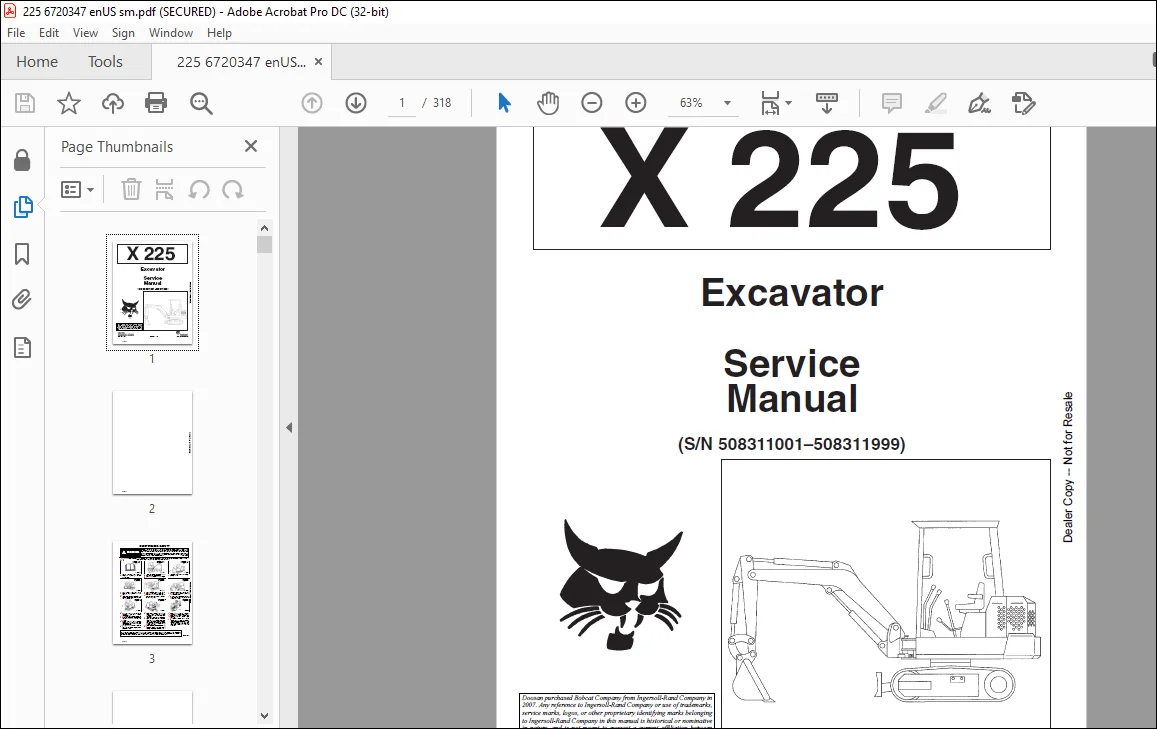
Bobcat Excavator X225 Service Manual 6720347 – PDF DOWNLOAD
(S/N 508311001–508311999)
Description
Bobcat Excavator X225 Service Manual 6720347 – PDF DOWNLOAD
FILE DETAILS:
Bobcat Excavator X225 Service Manual 6720347 – PDF DOWNLOAD
Language : English
Pages :318
Downloadable : Yes
File Type : PDF
Size:10.8 MB
DESCRIPTION:
Bobcat Excavator X225 Service Manual 6720347 – PDF DOWNLOAD
FOREWORD
This manual is for the Bobcat hydraulic excavator mechanic. It provides necessary servicing an d adjustment procedures for the hydraulic excavator and its component parts and systems. Refer to the Operation & Maintenance Manual for operating instructions, starting procedure, daily checks, etc.
A general inspection of the following items must be made after the hydraulic excavator has had service
or repair:
• The Delivery Report is used to assure that complete instructions have been given to the new owner and that the machine
is in safe operating condition.
• The Operation & Maintenance Manual delivered with the excavator gives operating information as well as routin e
maintenance and service procedures. It is a part of the excavator and must stay with the machine when it is sol d.
Replacement Operation & Maintenance Manuals can be ordered from your Bobcat Excavator dealer.
• The excavator has machine signs (decals) which instruct on the safe operation and care. The signs and their locations
are shown in the Operation & Maintenance Manual. Replacement signs are available from your Bobcat Excavator dealer.
• The CIMA Safety Manual delivered with the excavator gives information for safe operating and standard signals.
• The Service Manual and Parts Manual are available from Bobcat Excavator dealers for use by mechanics to do shop–type
service and repair work.
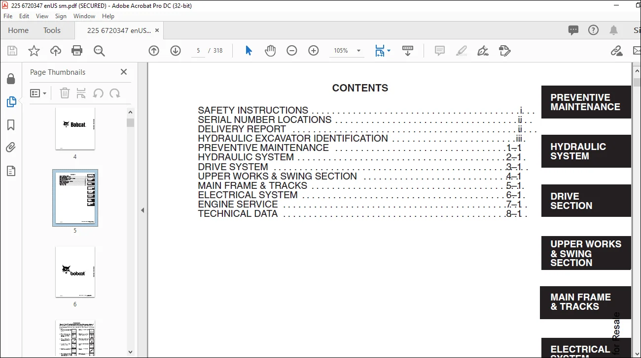
TABLE OF CONTENTS:
Bobcat Excavator X225 Service Manual 6720347 – PDF DOWNLOAD
MAINTENANCE SAFETY 3
CONTENTS 5
FOREWORD 7
SAFETY INSTRUCTIONS 9
SERIAL NUMBER LOCATIONS 10
HYDRAULIC EXCAVATOR SERIAL NUMBER 10
ENGINE SERIAL NUMBER 10
DELIVERY REPORT 10
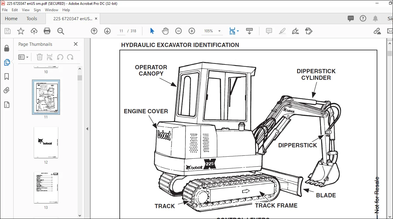
HYDRAULIC EXCAVATOR IDENTIFICATION 11
PREVENTIVE MAINTENANCE 13
SERVICE SCHEDULE 15
ENGINE COVER 16
Procedure 16
AIR CLEANER SERVICE 16
Replacing The Filter Element 16
FUEL SYSTEM 17
Fuel Specifications 17
Fuel System Service 17
ENGINE LUBRICATION SYSTEM 19
Checking The Engine Oil 19
Engine Oil And Filter Replacement 19
COOLING SYSTEM 20
Coolant Level 20
Coolant Replacement 20
HYDRAULIC SYSTEM 21
Checking And Adding Fluid 21
Replacement Of The Hydraulic Filters 22
Hydraulic Reservoir 22
USING A BOOSTER BATTERY (JUMP STARTING) 23
Procedure 23
LUBRICATION OF THE HYDRAULIC EXCAVATOR 24
Procedure 24
FINAL DRIVE CASE 26
Checking Oil Level 26
HYDRAULIC SECTION 27
HYDRAULIC SCHEMATICS 29
HYDRAULIC SERVICE INFORMATION 35
Description 35
Checking The Control Valve Relief Valves 35
Checking The Locking Lever Relief Valve 37
With Locking Lever Up (By–Passing Relief Valve) 37
Checking The Auxiliary Relief Valve 37
HYDRAULIC PUMP 38
Removal And Installation 38
Disassembly 39
Assembly 41
HYDRAULIC CONTROL VALVE 45
Removal And Installation 45
CONTROL VALVE 47
Disassembly And Assembly 47
Relief Valve Pressure Setting Adjustment 62
Main Relief Valve 62
Work Port Relief Valves 64
HYDRAULIC RESERVOIR 65
Removal And Installation 65
Suction Filter 66
BOOM CYLINDER 67
Removal And Installation 67
DIPPERSTICK CYLINDER 68
Removal And Installation 68
BUCKET CYLINDER 69
Removal And Installation 69
BLADE CYLINDER 70
Removal And Installation 70
BOOM SWING CYLINDER 71
Removal And Installation 71
HYDRAULIC CYLINDER 72
Disassembly 72
Assembly 76
SWING CYLINDER LOCK VALVE 82
Parts Identification 82
Disassembly 83
Assembly 84
SOLENOID VALVE 86
Parts Identification 86
Disassembly 87
Assembly 90
HYDRAULIC FILTER 94
Removal And Installation 94
Untitled 95
DRIVE SECTION 97
HYDRAULIC CONTROL LEVERS 99
Swing/Dipperstick Control Lever 99
Boom/Bucket Control Lever 101
Disassembly And Assembly 101
THROTTLE LEVER 105
Removal And Installation 105
BLADE CONTROL LEVER 105
Removal And Installation 105
CONTROL LOCKING ARM 106
Removal And Installation 106
PANEL LIFT CYLINDER 107
Removal And Installation 107
LOCKING LEVER VALVE 108
Removal And Installation 108
LOCKING LEVER CABLE 109
Removal And Installation 109
CONTROL PANEL BASE 110
Removal And Installation 110
FOOT PEDAL AND STEERING LEVER LINKAGE 111
Removal And Installation 111
STEERING LEVERS 112
Removal And Installation 112
FINAL DRIVE 113
Removal And Installation 113
DRIVE MOTOR 115
Disassembly 115
Assembly 127
FINAL DRIVE CASE 138
Check Oil Level 138
Draining Final Drive Case 138
UPPER WORKS AND SWING SECTION 139
SWING MOTOR 141
Removal And Installation 141
SWING MOTOR ASSEMBLY 142
Brake Valve 142
Parts Identification 142
Disassembly 143
Assembly 146
Relief Valve 149
Disassembly 149
Assembly 150
Adjustment for Model 225 152
Piston Housing 153
Parts Identification 153
Disassembly 154
Assembly 157
Reduction Gear 162
Parts Identification 162
Disassembly 163
Assembly 167
UPPER WORKS 172
Removal And Installation 172
SWING CIRCLE GEAR 173
Removal And Installation 173
CENTER SWIVEL JOINT 174
Removal And Installation 174
Disassembly And Assembly 174
MAIN FRAME AND TRACKS 175
ENGINE COVER 177
Removal And Installation 177
FLOOR PANELS 178
Removal And Installation 178
SEAT AND MOUNTING FRAME 180
Removal And Installation 180
SWING MOTOR COVER 180
Removal And Installation 180
FUEL TANK 181
Removal And Installation 181
BUCKET 182
Removal And Installation 182
DIPPERSTICK 183
Removal And Installation 183
BOOM 183
Removal And Installation 183
BOOM SWING BRACKET 185
Removal And Installation 185
BLADE 186
Removal And Installation 186
TRACK 187
Track Tension Adjustment 187
TRACK FRAME 189
Disassembly And Assembly 189
TRACK IDLER 190
Parts Identification 190
Disassembly 191
Assembly 193
RUBBER TRACK IDLER 197
Parts Identification 197
Disassembly 198
Assembly 200
TOOL BOX 204
Removal And Installation 204
TRACK ROLLER 205
Parts Identification 205
Disassembly 206
Assembly 208
RUBBER TRACK ROLLER 212
Parts Identification 212
Disassembly 213
Assembly 215
ROPS WINDOWS 219
Front Window Removal 219
Side Window Removal 220
ELECTRICAL SYSTEM 221
ELECTRICAL SCHEMATICS 223
TROUBLESHOOTING 225
Chart 225
ELECTRICAL SYSTEM 225
Description 225
Fuses 226
Electrical System Service 226
BATTERY 227
Checking The Battery 227
Removal And Installation 227
ALTERNATOR 228
Belt Adjustment 228
Removal And Installation 228
STARTER 229
Removal And Installation 229
Disassembly And Assembly 230
Cleaning And Inspection 230
FUEL LEVEL SENDER 231
Removal And Installation 231
Checking 231
DISPLAY MODULE 232
Removal And Installation 232
INSTRUMENT PANEL 232
Removal And Installation 232
Testing And Troubleshooting 233
Engine Temperature Circuit Test (display module installed) 235
Testing The Display Panel 235
Fuel Level Circuit Test (display module installed) 237
Testing The Display Panel 237
Fuel Level Sender 238
Engine Oil Pressure Circuit Test (display module installed) 239
Testing The Display Panel 239
Battery Charge Circuit Test (display module installed) 240
Glow Plug Circuit Test (display module installed) 241
Engine Temperature Circuit Test (display module removed) 242
Fuel Level Circuit Test (display module removed) 243
Engine Oil Pressure Circuit Test (display module removed) 244
Battery Charge Circuit Test (display module removed) 245
Glow Plug Circuit Test (display module removed) 246
VOLTAGE REGULATOR/GLOW PLUG TIMER 247
Removal And Installation 247
WIPER MOTOR AND SWITCH 248
ENGINE SERVICE 251
TROUBLESHOOTING 253
Chart 253
VALVE CLEARANCE 254
Adjustment 254
ENGINE COMPRESSION 255
Checking 255
FUEL FILTER 256
Final Filter 256
In–Line Filter 256
ELECTRIC FUEL PUMP 257
Removal And Installation 257
FUEL INJECTION PUMP 258
Checking The Injection Pump 258
Removal And Installation 259
Timing The Injection Pump 260
FUEL INJECTOR NOZZLES 261
Removal And Installation 261
Checking The Injector Nozzle 262
GLOW PLUGS 263
Removal And Installation 263
Checking The Glow Plug 263
RADIATOR 264
Removal And Installation 264
MUFFLER 266
Removal And Installation 266
AIR CLEANER 267
Removal And Installation 267
ENGINE 268
Removal And Installation 268
ENGINE FLYWHEEL 269
Removal And Installation 269
Flywheel Ring Gear 271
CYLINDER HEAD 272
Removal 272
Disassembly 273
Servicing The Cylinder Head And Valves 274
Checking Valve Springs 275
Checking Rocker Arm And Shaft 276
Assembling The Cylinder Head 276
Installation 276
TIMING GEAR COVER 278
Removal And Installation 278
TIMING GEAR, CAMSHAFT AND OIL PUMP 280
Removal And Installation 280
Oil Pump Service 282
Servicing The Camshaft 283
CRANKSHAFT AND PISTONS 284
Removal And Installation 284
Crankshaft Service 287
Servicing The Connecting Rods And Pistons 288
CYLINDER LINERS 290
Checking The Cylinder Liners 290
Cylinder Liner Installation 290
WATER PUMP 291
Removal And Installation 291
Disassembly And Assembly 291
TECHNICAL DATA 293
EXCAVATOR SPECIFICATIONS 295
Machine Dimensions 295
Performance And Operation 296
Engine 296
Hydraulic System 296
Swing System 296
Hydraulic Cylinders 296
Drive System 297
Brakes 297
Track Shoes 297
Capacities 297
Digging Force 297
ENGINE SPECIFICATIONS 298
Fuel Injection Nozzles 298
Fuel Injection Pump 298
Cylinder Head 298
Valves 298
Valve Springs 298
Rocker Arms 298
Camshaft 298
Cylinder 299
Piston Rings 299
Pistons 299
Crankshaft 299
Oil Pump 299
Engine Oil Specifications 299
Engine Bolt Torque 300
Re–Grinding The Crankshaft 301
FUEL, COOLANT AND LUBRICANTS 302
Chart 302
OIL SPECIFICATIONS 302
Description 302
SERVICE MANUAL REVISION 303
225-1 303
225-2 305
225-3 307
225-4 309
225-5 311
225-6 313
225-7 315
225-8 317
IMAGES PREVIEW OF THE MANUAL:
Questions? Email us: [email protected]
PLEASE NOTE:
- This is the same manual used by the dealers to diagnose and troubleshoot your vehicle
- You will be directed to the download page as soon as the purchase is completed. The whole payment and downloading process will take anywhere between 2-5 minutes
- Need any other service / repair / parts manual, please feel free to contact [email protected] . We still have 50,000 manuals unlisted
s.m