Bobcat Excavator X225 Service Manual 6720874 (6-12) – PDF DOWNLOAD
$28.95
Bobcat Excavator X225 Service Manual 6720874 (6-12) – PDF DOWNLOAD
(S/N 508312000 & Above)
Description
Bobcat Excavator X225 Service Manual 6720874 (6-12) – PDF DOWNLOAD
FILE DETAILS:
Bobcat Excavator X225 Service Manual 6720874 (6-12) – PDF DOWNLOAD
Language : English
Pages :328
Downloadable : Yes
File Type : PDF
Size:12.7 MB
DESCRIPTION:
Bobcat Excavator X225 Service Manual 6720874 (6-12) – PDF DOWNLOAD
FOREWORD
This manual is for the Bobcat hydraulic excavator mechanic. It provides necessary servicing an d adjustment procedures for the hydraulic excavator and its component parts and systems. Refer to the Operation & Maintenance Manual for operating instructions, starting procedure, daily checks, etc.
A general inspection of the following items must be made after the hydraulic excavator has had service
or repair:
• The Delivery Report is used to assure that complete instructions have been given to the new owner and that the machine
is in safe operating condition.
• The Operation & Maintenance Manual delivered with the loader gives operating information as well as routin e
maintenance and service procedures. It is a part of the loader and must stay with the machine when it is sold. Replacement
Operation & Maintenance Manuals can be ordered from your Bobcat Excavator dealer.
• The excavator has machine signs (decals) which instruct on the safe operation and care. The signs and their locations
are shown in the Operation & Maintenance Manual. Replacement signs are available from your Bobcat Excavator dealer.
• The CIMA Safety Manual delivered with the excavator gives information for safe operating and standard signals.
• The Service Manual and Parts Manual are available from your dealer for use by mechanics to do shop–type service and
repair work
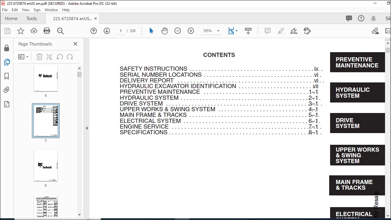
TABLE OF CONTENTS:
Bobcat Excavator X225 Service Manual 6720874 (6-12) – PDF DOWNLOAD
MAINTENANCE SAFETY 3
CONTENTS 5
FOREWORD 7
SAFETY INSTRUCTIONS 9
SERIAL NUMBER LOCATIONS 11
HYDRAULIC EXCAVATOR SERIAL NUMBER 11
ENGINE SERIAL NUMBER 11
DELIVERY REPORT 11
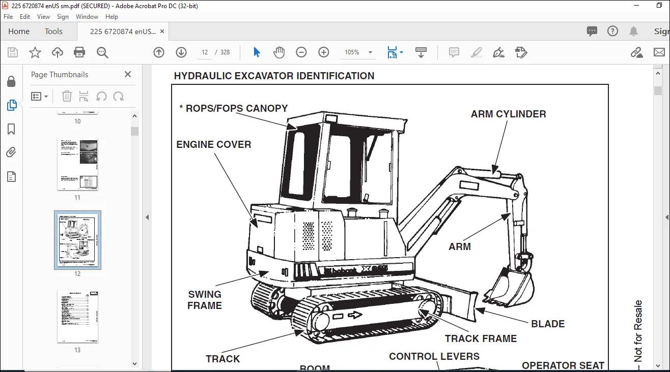
HYDRAULIC EXCAVATOR IDENTIFICATION 12
PREVENTIVE MAINTENANCE 13
SERVICE SCHEDULE 15
ENGINE COVER 16
Procedure 16
AIR CLEANER SERVICE 16
Replacing the Filter Element 16
FUEL SYSTEM 17
Fuel Specifications 17
Fuel System Service 17
Fuel Filters (S/N 12648 & Above) 18
ENGINE LUBRICATION SYSTEM 19
Checking the Engine Oil 19
Engine Oil and Filter Replacement 19
COOLING SYSTEM 20
Coolant Level 20
Coolant Replacement 20
HYDRAULIC SYSTEM 21
Checking and Adding Fluid 21
Replacement of the Hydraulic Filter 21
Hydraulic Reservoir 22
USING A BOOSTER BATTERY (Jump Starting) 23
Procedure 23
LUBRICATION OF THE HYDRAULIC EXCAVATOR 24
Procedure 24
FINAL DRIVE CASE 26
Checking Oil Level 26
Draining Final Drive Case 26
Untitled 27
HYDRAULIC SECTION 27
HYDRAULIC SCHEMATICS 29
HYDRAULIC SERVICE INFORMATION 41
Description 41
Checking the Relief Valves 41
HYDRAULIC PUMP 43
Disassembly & Assembly 43
Parts Identification 43
HYDRAULIC CONTROL VALVE (6 Spool) 48
Removal and Installation 48
Parts Identification 49
Disassembly and Assembly 50
Disassembly 50
Inlet Section (R H and L H Travel) Disassembly 51
Inlet Section (R H and L H Travel) Assembly 52
Valve Sections (Boom, Bucket & Arm) Disassembly 53
Valve Sections (Boom, Bucket & Arm) Assembly 54
Valve Sections (Auxiliary) Disassembly 55
Valve Sections (Auxiliary) Assembly 56
Port Relief Valve 58
Disassembly 58
Assembly 58
Adjustment Procedure 58
Main Relief Valve 60
Disassembly 60
Assembly 60
Adjustment Procedure 61
HYDRAULIC CONTROL VALVE (3 Spool) 63
Removal and Installation 63
Parts Identification 64
Disassembly 65
Inlet Section (Housing Swing) 66
Disassembly 66
Assembly 66
End Cover (Boom Swing) and Valve Section (Blade) Disassembly 67
End Cover (Boom Swing) and Valve Section (Blade) Assembly 69
Load Check Block 71
Disassembly 71
Assembly 71
Build–Up Valve 73
Assembly 73
Main Relief Valve 74
Disassembly 74
Assembly 74
Main Relief Valve Adjustment Procedure 75
PRESSURE REDUCING VALVE WITHACCUMULATOR 77
Removal and Installation 77
Parts Identification 77
ACCUMULATOR / VALVE 78
Disassembly 78
Assembly 82
Setting the Safety Relief Valve 86
ACCUMULATOR 87
Charging 87
PORT BLOCK 88
Removal and Installation 88
OIL COOLER 89
Removal and Installation 89
HYDRAULIC RESERVOIR 90
Removal and Installation 90
HYDRAULIC FILTER ASSEMBLY 91
Removal and Installation 91
BOOM CYLINDER 92
Removal and Installation 92
BOOM DROP VALVE (NORDIC–OPTION) 92
Removal and Installation 92
ARM CYLINDER 93
Removal and Installation 93
BUCKET CYLINDER 94
Removal and Installation 94
BLADE CYLINDER 95
Removal and Installation 95
BOOM SWING CYLINDER 97
Removal and Installation 97
HYDRAULIC CYLINDER 98
Disassembly 98
Assembly 100
JOYSTICK CONTROL CHANGE 105
DRIVE SYSTEM 107
LEFT CONSOLE 109
Lockout Valve Removal and Installation 109
Cylinder Removal and Installation 109
Removal and Installation 110
LEFT JOYSTICK 111
Removal and Installation 111
Parts Identification 111
JOYSTICK 112
Disassembly and Assembly 112
CONTROL LEVERS 116
Removal and Installation 116
Throttle Lever 117
Blade Lever 118
RIGHT CONSOLE 119
Removal and Installation 119
Parts Identification 120
FOOT PEDAL AND STEERING LEVERS 121
Removal and Installation 121
Bushing Removal and Installation 122
FINAL DRIVE 123
Removal and Installation 123
Parts Identification 124
DRIVE MOTOR 127
Disassembly 127
Assembly 139
FINAL DRIVE CASE 150
Check Oil Level 150
Draining Final Drive Case 150
UPPER WORKS AND SWING SYSTEM 151
SWING MOTOR 153
Removal and Installation 153
Parts Identification 154
SWING GEAR BOX ASSEMBLY(WITH OR WITHOUT BRAKES) 155
Disassembly 155
Assembly 164
SWING GEAR BRAKE (NORDIC OPTION) 178
Solenoid Removal and Installation 178
UPPER WORKS AND SWING CIRCLE GEAR 179
Removal and Installation 179
Swing Bearing Removal 181
Swing Bearing Installation 182
Alignment Pins (Not Threaded) 184
CENTER SWIVEL JOINT 185
Removal and Installation (through upper access removal) 185
Parts Identification 187
MAIN FRAME AND TRACKS 189
ENGINE COVER 191
Removal and Installation 191
SEAT AND MOUNTING FRAME 191
Removal and Installation 191
NORDIC SEAT AND MOUNTING FRAME (OPTIONAL) 192
Removal and Installation 192
CENTER FLOOR PANEL 192
Removal and Installation 192
SWING MOTOR COVER 193
Removal and Installation 193
REAR FLOOR PANEL 193
Removal and Installation 193
INSPECTION COVER 194
Removal and Installation 194
TOOL BOX 194
Removal and Installation 194
FUEL TANK 195
Removal and Installation 195
BUCKET 196
Removal and Installation 196
ARM 197
Removal and Installation 197
BOOM 197
Removal and Installation 197
BOOM SWING BRACKET 199
Removal and Installation 199
BLADE 200
Removal and Installation 200
TRACK 201
Track Tension Adjustment 201
Removal and Installation 202
TRACK FRAME 203
Disassembly and Assembly 203
TRACK IDLER 205
Parts Identification 205
Disassembly 206
Assembly 208
TRACK IDLER 212
Parts Identification 212
Disassembly 213
Assembly 215
TRACK ROLLER 219
Parts Identification 219
Disassembly 220
Assembly 222
Parts Identification 226
Disassembly 227
Assembly 229
ROPS 233
Removal and Installation 233
NORDIC CAB (OPTIONAL) 233
Removal and Installation 233
ROPS WINDOW 234
Front Window Removal 234
Side Window Removal 235
Installation 235
ELECTRICAL SYSTEM 237
ELECTRICAL SCHEMATICS 239
TROUBLESHOOTING 241
ELECTRICAL SYSTEM 241
Description 241
Fuses 242
Electrical System Service 242
BATTERY 243
Checking the Battery 243
Removal and Installation 243
ALTERNATOR 244
Belt Adjustment 244
Removal and Installation 244
STARTER 245
Removal and Installation 245
Disassembly and Assembly 246
Cleaning and Inspection 246
FUEL LEVEL SENDER 247
Removal and Installation 247
Checking 247
INSTRUMENT PANEL 248
Removal and Installation 248
DOME LIGHT 249
Removal and Installation 249
CAB CONTROL PANEL 249
Removal and Installation 249
FRONT LIGHTS 250
Removal and Installation 250
Lamp Replacement 250
CONSOLE SWITCHES 251
Removal and Installation 251
WINDSHIELD WIPER 252
Removal and Installation 252
WINDSHIELD WASHER (NORDIC OPTION) 253
Removal and Installation 253
Hose Removal 253
ENGINE COVER LIGHT (NORDIC OPTION) 254
Removal and Installation 254
ENGINE SERVICE 255
TROUBLESHOOTING 257
VALVE CLEARANCE 258
Adjustment 258
ENGINE COMPRESSION 259
Checking 259
ELECTRIC FUEL PUMP 260
Removal and Installation 260
In–Line Filter (Used on Early Model Excavators Only) 260
FUEL FILTER 261
Final Filter (S/N 12001–12647) 261
Fuel Filter (S/N 12648 & Above) (With Water Drain Valve) 261
FUEL INJECTION PUMP 262
Checking the Injection Pump 262
Removal and Installation 263
Timing the Injection Pump 264
FUEL INJECTION NOZZLES 265
Removal and Installation 265
GLOW PLUGS 267
Removal and Installation 267
Checking the Glow Plug 267
RADIATOR 268
Removal and Installation 268
FAN SHIELD (NORDIC OPTION) 269
Removal and Installation 269
MUFFLER 270
Removal and Installation 270
AIR CLEANER 271
Removal and Installation 271
ENGINE 272
Removal and Installation 272
ENGINE FLYWHEEL 273
Removal and Installation 273
Flywheel Ring Gear 275
CYLINDER HEAD 276
Removing the Cylinder Head 276
Disassembly of the Cylinder Head 277
Servicing the Cylinder Head and Valves 278
Checking Valve Springs 279
Checking Rocker Arm and Shaft 280
Assembling the Cylinder Head 280
Installing the Cylinder Head 280
TIMING GEAR COVER 282
Removal and Installation 282
TIMING GEAR, CAMSHAFT AND OIL PUMP 284
Removal and Installation 284
Oil Pump Service 286
Servicing the Camshaft 287
CRANKSHAFT AND PISTONS 289
Removal and Installation 289
Crankshaft Service 291
Servicing the Connecting Rods and Pistons 292
CYLINDER LINERS 294
Checking the Cylinder Liners 294
Cylinder Liner Installation 294
WATER PUMP 295
Removal and Installation 295
Disassembly and Assembly 295
SPECIFICATIONS 297
HYDRAULIC EXCAVATOR SPECIFICATIONS 299
Machine Dimensions 299
Lifting Capacity With Blade Off Ground 300
OPERATION & PERFORMANCE 300
ENGINE 300
HYDRAULIC SYSTEM 301
SWING SYSTEM 301
HYDRAULIC CYLINDERS 301
DRIVE SYSTEM 301
UNDERCARRIAGE 301
TRACK 301
CAPACITIES 301
DIGGING FORCE 301
ENGINE SPECIFICATIONS 302
Fuel Injection Nozzles 302
Fuel Injection Pump 302
Cylinder Head 302
Valves 302
Valve Springs 302
Rocker Arms 302
Camshaft 302
Cylinders 303
Piston Rings 303
Pistons 303
Crankshaft 303
Oil Pump 303
Engine Oil 303
Specifications 303
ENGINE TORQUE 304
Re–Grinding The Crankshaft 305
FUEL, COOLANT AND LUBRICANTS 306
OIL SPECIFICATIONS 306
Description 306
SERVICE MANUAL REVISION 307
225-1 307
225-2 309
225-3 311
225-4 313
225-5 315
225-6 317
225-7 319
225-8 321
225-9 323
225-10 325
225-11 327
IMAGES PREVIEW OF THE MANUAL:
Need help? Contact: [email protected]
https://vimeo.com/840010578?share=copy
PLEASE NOTE:
- This is the same manual used by the DEALERSHIPS to SERVICE your vehicle.
- The manual can be all yours – Once payment is complete, you will be taken to the download page from where you can download the manual. All in 2-5 minutes time!!
- Need any other service / repair / parts manual, please feel free to contact us at heydownloadss @gmail.com . We may surprise you with a nice offer
S.M