Bobcat Excavator X320 322 Service Manual 6724910 – PDF DOWNLOAD
$29.95
Bobcat Excavator X320 322 Service Manual 6724910 – PDF DOWNLOAD
(S/N 562313001 & Above)
(S/N 517811001 & Above)
Description
Bobcat Excavator X320 322 Service Manual 6724910 – PDF DOWNLOAD
FILE DETAILS:
Bobcat Excavator X320 322 Service Manual 6724910 – PDF DOWNLOAD
Language : English
Pages : 396
Downloadable : Yes
File Type : PDF
Size:15.7 MB
DESCRIPTION:
Bobcat Excavator X320 322 Service Manual 6724910 – PDF DOWNLOAD
FOREWORD
This manual is for the Bobcat hydraulic excavator mechanic. It provides necessary servicing an d
adjustment procedures for the hydraulic excavator and its component parts and systems. Refer to the
Operation & Maintenance Manual for operating instructions, starting procedure, daily checks, etc
A general inspection of the following items must be made after the hydraulic excavator has had service
or repair:
• The Delivery Report is used to assure that complete instructions have been given to the new owner and that the machine
is in safe operating condition.
• The Operation & Maintenance Manual delivered with the excavator gives operating information as well as routin e
maintenance and service procedures. It is a part of the excavator and must stay with the machine when it is sol d.
Replacement Operation & Maintenance Manuals can be ordered from your Bobcat Excavator dealer.
• The excavator has machine signs (decals) which instruct on the safe operation and care. The signs and their locations
are shown in the Operation & Maintenance Manual. Replacement signs are available from your Bobcat Excavator dealer.
Safety Alert Symbol: This Safety Symbol is used for important safety messages. When you see this symbol follow
the safety message to avoid personal injury or death.
• The Bobcat Hydraulic Excavator has a plastic Operator’s Handbook fastened to the operator cab. It’s brief instructions
are convenient to the operator. The handbook is available from your dealer in an English, French, German, Dutch, Italian,
Spanish, Portugese, Finnish, Danish, and Swedish editions.
• The CIMA Safety Manual delivered with the excavator gives information for safe operating and standard signals.
• The Service Manual and Parts Manual are available from your dealer for use by mechanics to do shop–type service and
repair work.
• The Bobcat compact Excavator Operator Training Course is available through your local dealer. This course is intended
to provide rules and practices of correct operation of the Hydraulic Excavator.
TABLE OF CONTENTS:
Bobcat Excavator X320 322 Service Manual 6724910 – PDF DOWNLOAD
MAINTENANCE SAFETY 3
ALPHABETICAL INDEX 5
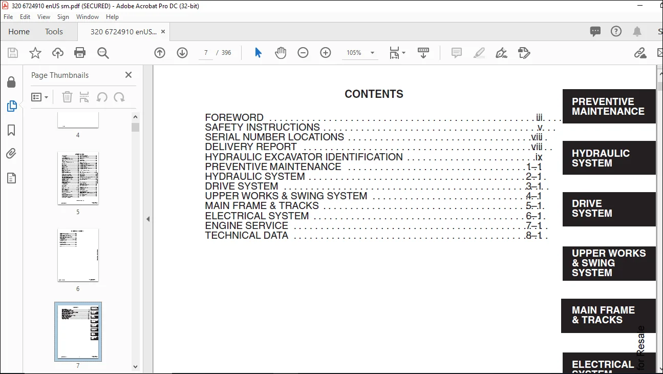
CONTENTS 7
FOREWORD 9
SAFETY INSTRUCTIONS 11
SERIAL NUMBER LOCATIONS 14
HYDRAULIC EXCAVATOR SERIAL NUMBER 14
ENGINE SERIAL NUMBER 14
DELIVERY REPORT 14
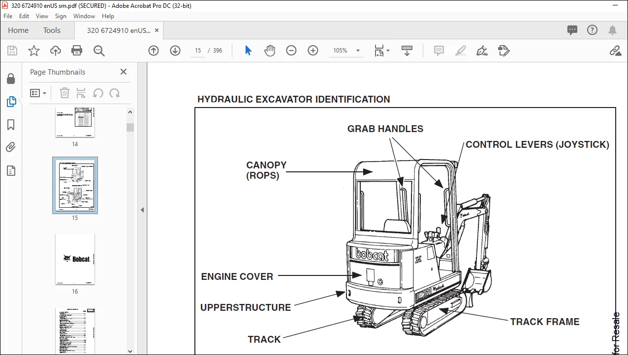
HYDRAULIC EXCAVATOR IDENTIFICATION 15
PREVENTIVE MAINTENANCE 17
MAINTENANCE SAFETY 19
SERVICE SCHEDULE 20
ENGINE COVER 21
Adjustment of the Engine Cover Latch 21
AIR CLEANER SERVICE 21
Daily Check 21
Filter Replacement 22
FUEL SYSTEM 23
Filling the Fuel Tank 23
Fuel Filter 23
Fuel System Maintenance 24
Removing Air From the Fuel System 24
Fuel Specification 24
ENGINE LUBRICATION SYSTEM 25
Checking Engine Oil 25
Replacement of Oil and Filter 25
COOLING SYSTEM 26
Coolant Level 26
Coolant Replacement 26
Propylene Glycol (Factory Installed) 26
ALTERNATOR BELT ADJUSTMENT 27
ELECTRICAL SYSTEM 27
Electrical Relays and Diodes 27
Fuses 28
Service the Electrical System (and Battery) 28
Removal and Installation of the Battery 29
Electric Solenoid (Engine Stop) 29
HYDRAULIC SYSTEM 30
Checking and Adding Fluid 30
Diagnostic Couplers 31
Hydraulic Reservoir 31
Replacement of the Hydraulic Filter 31
Case Drain Hydraulic Filter 31
TRACK TENSION 33
Adjustment 33
FINAL DRIVE CASE 34
Checking Oil Level 34
Draining Final Drive Case 34
JOYSTICK CONTROL CHANGE 35
ISO to Standard Control Pattern 35
Standard to ISO Control Pattern 36
LUBRICATION OF THE HYDRAULIC EXCAVATOR 37
HEATER AIR FILTER (With Cab Option Only) 39
HYDRAULIC SECTION 41
HYDRAULIC SCHEMATICS 43
TROUBLESHOOTING 61
HYDRAULIC SERVICE INFORMATION 66
Checking the Main Relief Valves and Cross Port Relief Valve 66
Checking the Hydraulic Pump 71
HYDRAULIC PUMP 72
Removal and Installation 72
Coupler Removal and Installation 73
Hydraulic Pump Assembly 74
Disassembly 75
Assembly 77
HYDRAULIC CONTROL VALVE 80
Description 80
Removal and Installation 80
Disassembly 83
Outlet Section Disassembly 84
Outlet Section Assembly 84
Mid Inlet Section Disassembly 84
Mid Inlet Section Assembly 84
Left Travel, Right Travel, Auxiliary and Blade Disassembly 85
Left Travel, Right Travel, Auxiliary and Blade Assembly 87
Boom, Bucket Arm and Swing Disassembly 89
Boom, Bucket, Arm and Swing Assembly 92
Utility Block Disassembly 94
Utility Block Assembly 95
Boom Swing Disassembly 96
Boom Swing Assembly 98
Boost Disassembly 101
Boost Assembly 103
Assembly 106
PORT RELIEF VALVES 108
Parts Identification 108
Port Relief Valve Pressure Setting 109
Disassembly 109
Assembly 110
Adjustment Procedure 110
Disassembly 111
Assembly 111
Adjusting the Main Relief Valves 113
ACCUMULATOR 114
Pressure Reducing Valve (Description) 114
Removal and Installation 114
Disassembly (S/N 562313001 – 562320721 &517811001 – 517811977) 115
Assembly (S/N 562313001 – 562320721 & 517811001– 517811977) 117
Parts Identification (S/N 562320721 & Above & 517811978 & Above) 120
Disassembly (S/N 562320721 & Above & 517811978 & Above) 121
Assembly (S/N 562320721 & Above & 517811978 & Above) 123
Testing (All Models) 126
BOOM CYLINDER 128
Removal and Installation 128
ARM CYLINDER 129
Removal and Installation 129
BUCKET CYLINDER 130
Removal and Installation 130
BLADE CYLINDER 131
Removal and Installation 131
BOOM SWING CYLINDER 132
Removal and Installation 132
TRACK FRAME EXPANSION CYLINDER 322 (S/N 517811001 & Above) 133
HYDRAULIC CYLINDER 137
Disassembly 137
Assembly 139
Disassembly 140
Assembly 141
HYDRAULIC FILTER ASSEMBLY 147
Removal and Installation 147
AUXILIARY FLUSH FACE COUPLERS 147
Removal and Installation 147
DRAIN BLOCK 148
Removal and Installation 148
OIL COOLER 148
Removal and Installation 148
JOYSTICK CONTROL CHANGE 149
ISO To Standard 149
Standard to ISO 149
DRIVE SECTION 151
FLOORMAT AND FLOOR PANELS 153
Removal and Installation 153
MICROSWITCH 155
Adjustment 155
Removal and Installation 156
CONSOLE COVER LEFT HAND 157
Removal and Installation 157
JOYSTICK 159
Removal and Installation 159
CONTROL CONSOLE LEFT HAND 160
Removal and Installation 160
FUEL TANK 163
Removal and Installation 163
LOCK LEVER 165
Removal and Installation 165
Adjustment 166
LATCH HOOK 167
Removal and Installation 167
GAS SPRING 168
Removal and Installation 168
UPPER CONSOLE 169
Removal and Installation 169
CONTROL CONSOLE RIGHT HAND 170
Rops Canopy Models 170
Cab Models 170
CONSOLE COVER RIGHT HAND 171
Removal and Installation 171
CONTROL CONSOLE RIGHT HAND 173
Removal and Installation 173
HYDRAULIC RESERVOIR 178
Removal and Installation 178
TRAVEL LEVERS 179
Removal and Installation 179
Disassembly and Assembly 180
PEDAL RIGHT HAND 182
Removal and Installation 182
Disassembly and Assembly 182
PEDAL LEFT HAND 184
Removal and Installation 184
Disassembly and Assembly 184
ROCKERSHAFT 186
Removal and Installation 186
Disassembly and Assembly 187
LINKAGE RODS 188
Removal and Installation 188
BLADE LEVER 189
Removal and Installation 189
Disassembly and Assembly 191
DRIVE MOTOR 192
Removal and Installation 192
Parts Identification 193
Disassembly 194
Assembly 201
JOYSTICK 210
Parts Identification 210
Disassembly 211
Assembly 214
Troubleshooting 219
UPPER WORKS AND SWING SECTION 221
SWING MOTOR 223
Removal and Installation 223
Disassembly 224
Assembly 225
Motor Timing 226
CENTER SWIVEL JOINT (S/N 562313001 – 562319999) 227
Removal and Installation 227
Disassembly and Assembly 227
CENTER SWIVEL JOINT 320 (S/N 562320000 &Above) and 322 (S/N 517811001 & Above) 228
Removal And Installation 228
Parts Identification 234
Disassembly 235
Assembly 239
UPPERSTRUCTURE 243
Removal 243
Installation 245
SWING CIRCLE GEAR 247
Removal and Installation 247
ROPS CANOPY 248
Removal and Installation 248
CAB 250
Removal and Installation 250
Door (Removal and Installation) 253
Front Window Removal and Installation 254
Front Lower Window Removal and Installation 255
Front Upper Window Removal and Installation 255
Door Glass (Removal and Installation) 256
Left Hand Side Glass (Removal and Installation) 256
Right Hand Side Window Removal and Installation 257
Right Hand Window Assembly Removal and Installation 258
Rear Window Removal and Installation 258
CAB/CANOPY REAR COVER 259
Removal 259
Installation 259
AIR BAFFLE (Cab Models Only) 260
Removal and Installation 260
BELLY PAN (Field Installed) 260
Removal and Installation 260
MAIN FRAME AND TRACKS 261
ENGINE COVER 263
Removal and Installation 263
CORNER POSTS 263
Removal and Installation 263
COUNTERWEIGHT 264
Removal and Installation 264
SEAT AND SEAT MOUNT 265
Removal and Installation 265
SPEED CONTROL LEVER/SWING LOCK LEVER AND MOUNTING 266
Removal and Installation 266
BUCKET 267
Removal and Installation 267
Installation 267
ARM 268
Removal and Installation 268
ARM BUSHINGS 269
Arm To Boom Bushing Removal And Installation 269
Arm To Bucket and Bucket Link Bushing Removal and Installation 270
BOOM 271
Removal and Installation 271
BOOM BUSHING 272
Removal And Installation 272
SWING POST 273
Removal and Installation 273
Bushing Replacement 274
Swing Post Bushing Removal 274
Bushing Installation 274
TRACK 275
Adjustment 320 (S/N 562313001 – 562319999) 275
Adjustment 320 (S/N 562320000 & Above) and 322 (S/N 517811001 & Above) 276
Removal and Installation 277
Track Damage Identification and Causes 277
TRACK FRAME 278
Disassembly and Assembly 320 (S/N 562313001 – 562319999) 278
Disassembly and Assembly 320 (S/N 562320000 & Above) and 322 (S/N 517811001 & Above) 280
Recoil Spring Cylinder Disassembly And Assembly 282
Removal and Installation of Expandible Track Frame (322 only) 283
TRACK DAMAGE IDENTIFICATION 284
Cutting of the Steel Cords 284
Abrasion of Embedded Metals 285
Separation of Embedded Metals Due to External Forces 286
Separation of Embedded Metals Due To Corrosion 287
Cuts On The Lug Side 288
Cracks On The Lug Side Rubber Due To Fatigue 289
Lug Abrasion 290
Cracks and Cuts on the Lug Side Rubber at the Edges of the Embedded Metals 291
Abrasion Of The Track Roller Side Rubber Surface 292
Cuts On The Edges Of The Track Roller Side 293
ELECTRICAL SYSTEM 295
ELECTRICAL SCHEMATICS 297
TROUBLESHOOTING 309
Chart 309
ELECTRICAL SYSTEM 309
Description 309
Fuses 310
Electrical System Service 310
Electrical Relays and Diodes 311
BATTERY 312
Using A Booster Battery (Jump Starting) 312
Removal and Installation 313
BATTERY BOX 314
Removal and Installation 314
CAB ELECTRICAL (Cab Option) 314
Removal and Installation 314
ALTERNATOR 315
Checking the Alternator Output 315
Removal and Installation 315
Belt Adjustment 315
STARTER 316
Removal and Installation 316
Disassembly and Assembly 317
Cleaning and Inspection 317
HORN 318
Removal and Installation 318
FUEL LEVEL SENDER 318
Removal and Installation 318
LIGHT SWITCH 319
Removal and Installation 319
TWO SPEED SWITCH 320
Removal and Installation 320
ENGINE SERVICE 321
TROUBLESHOOTING 323
Chart 323
VALVE CLEARANCE 324
Adjustment 324
ENGINE COMPRESSION 324
Checking 324
FUEL SHUTOFF SOLENOID 325
Removal and Installation 325
Timer Module Removal and Installation 325
FUEL INJECTION PUMP 326
Checking the Injection Pump 326
Timing the Injection Pump 328
FUEL INJECTOR NOZZLES 329
Removal and Installation 329
Checking the Injector Nozzle 330
GLOW PLUGS 331
Removal and Installation 331
Checking the Glow Plug 331
BELT GUARD 332
Removal and Installation 332
RADIATOR 333
Removal and Installation 333
SPARK ARRESTOR MUFFLER (If Equipped) 336
Cleaning Spark Chamber 336
Removal and Installation 336
AIR CLEANER 337
Removal and Installation 337
ENGINE 338
Removal and Installation 338
ENGINE FLYWHEEL (EARLY MODELS) 343
Removal and Installation 343
Hydraulic Pump Coupler 344
ENGINE FLYWHEEL (LATER MODELS) 345
Removal And Installation 345
Hydraulic Pump Coupler 347
Flywheel Ring Gear 347
CYLINDER HEAD 348
Removal and Installation 348
Disassembly and Assembly 349
Servicing the Cylinder Head 350
Top Clearance 350
VALVE, VALVE SEAT AND GUIDE 351
Checking the Valve Guide 351
Reconditioning the Valve and Valve Seat 352
Valve Spring 353
ROCKER ARM AND SHAFT 353
Checking 353
TIMING GEARCASE COVER 354
Removal and Installation 354
IDLER GEAR AND CAMSHAFT 356
Removal and Installation 356
Servicing the Idler Gear and Shaft 358
TIMING GEARS 358
Checking Backlash 358
FUEL CAMSHAFT 359
Removal and Installation 359
CRANKSHAFT GEAR 360
Removal and Installation 360
OIL PUMP 360
Removal and Installation 360
Oil Pump Service 360
Checking Engine Oil Pressure 361
Relief Valve 361
PISTON AND CONNECTING ROD 362
Removal and Installation 362
Servicing the Piston and Connecting Rod 363
Connecting Rod Alignment 365
CRANKSHAFT AND BEARINGS 366
Removal and Installation 366
Servicing the Crankshaft and Bearings 367
CYLINDER BORE 370
Checking the Cylinder Bore 370
WATER PUMP 371
Removal and Installation 371
Disassembly and Assembly 371
TECHNICAL DATA 373
HYDRAULIC EXCAVATOR SPECIFICATIONS 375
Machine Dimensions 375
SPECIFICATIONS 376
ENGINE SPECIFICATIONS 378
Engine 378
Fuel Injector Nozzles 378
Fuel Injection Pump 378
Cylinder Head 378
Valves 378
Valve Springs 378
Rocker Arms 378
Camshaft 379
Cylinders 379
Piston Rings 379
Pistons 379
Crankshaft 379
Oil Pump 380
Thermostat 380
ENGINE BOLT TORQUE 381
Re–Grinding The Crankshaft 382
HYDRAULIC FLUID SPECIFICATIONS 383
Specifications 383
FUEL, COOLANT AND LUBRICANTS 384
Chart 384
SERVICE MANUAL REVISION 385
320-1 385
320-2 387
320/322-3 389
320/322-4 391
320/322-5 393
320/322-6 395
IMAGES PREVIEW OF THE MANUAL:
Contact us: [email protected]
PLEASE NOTE:
- This is the SAME MANUAL used by the dealerships to diagnose your vehicle
- No waiting for couriers / posts as this is a PDF manual and you can download it within 2 minutes time once you make the payment.
- Your payment is all safe and the delivery of the manual is INSTANT – You will be taken to the DOWNLOAD PAGE.
- So have no hesitations whatsoever and write to us about any queries you may have : heydownloadss @gmail.com
S.M