Bobcat Excavator X325 Service Manual 6724480 (6-12) – PDF DOWNLOAD
$29.95
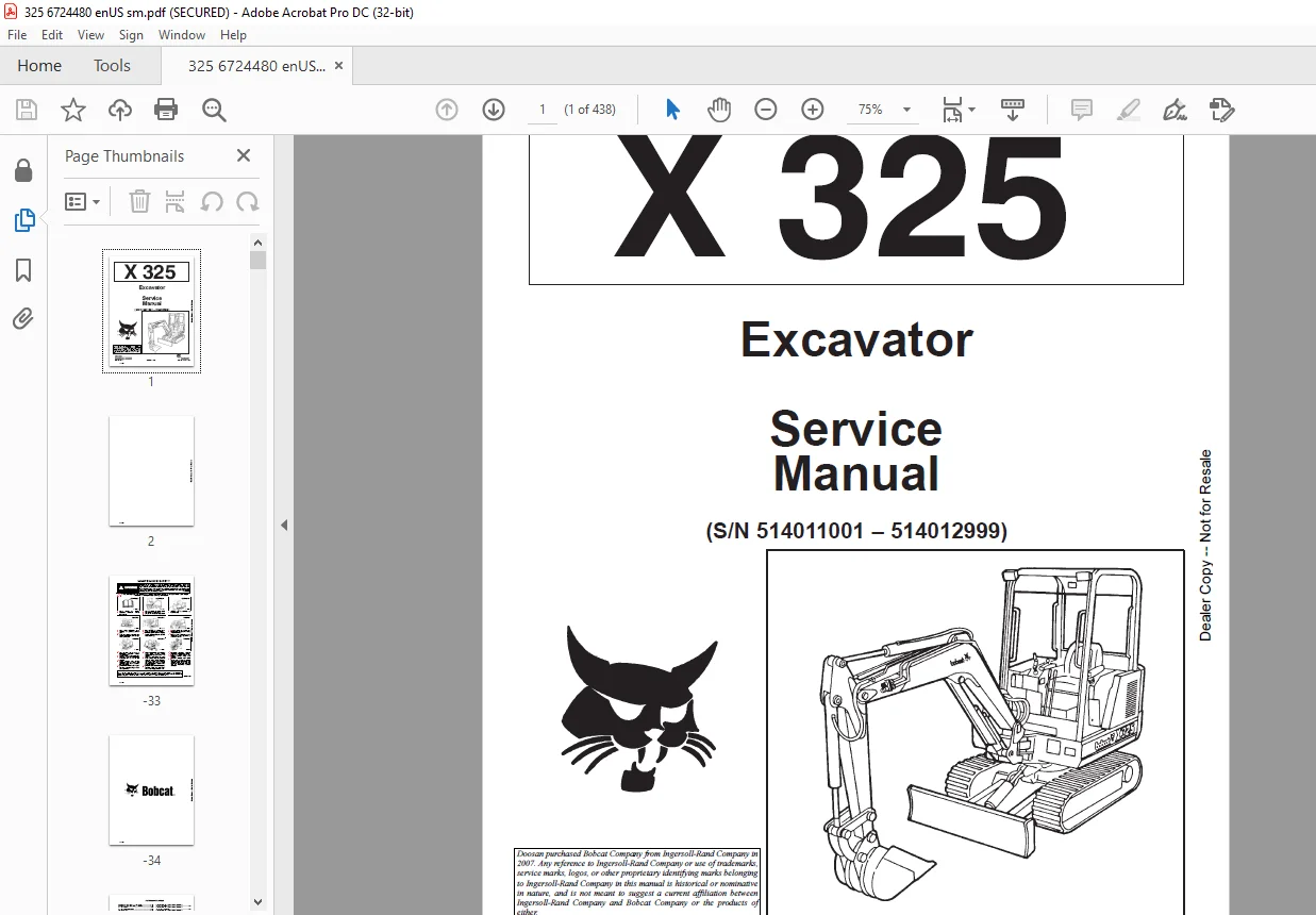
Bobcat Excavator X325 Service Manual 6724480 (6-12) – PDF DOWNLOAD
(S/N 514011001 – 514012999)
Description
Bobcat Excavator X325 Service Manual 6724480 (6-12) – PDF DOWNLOAD
FILE DETAILS:
Bobcat Excavator X325 Service Manual 6724480 (6-12) – PDF DOWNLOAD
Language : English
Pages : 438
Downloadable : Yes
File Type : PDF
Size:9.63 MB
DESCRIPTION:
Bobcat Excavator X325 Service Manual 6724480 (6-12) – PDF DOWNLOAD
FOREWORD
This manual is for the Bobcat hydraulic excavator mechanic. It provides necessary servicing an d
adjustment procedures for the hydraulic excavator and its component parts and systems. Refer to the
Operation & Maintenance Manual for operating instructions, starting procedure, daily checks, etc
A general inspection of the following items must be made after the hydraulic excavator has had service
or repair:
• The Delivery Report is used to assure that complete instructions have been given to the new owner and that the machine
is in safe operating condition.
• The Operation & Maintenance Manual delivered with the excavator gives operating information as well as routin e
maintenance and service procedures. It is a part of the excavator and must stay with the machine when it is sol d.
Replacement Operation & Maintenance Manuals can be ordered from your Bobcat Excavator dealer.
• The excavator has machine signs (decals) which instruct on the safe operation and care. The signs and their locations
are shown in the Operation & Maintenance Manual. Replacement signs are available from your Bobcat Excavator dealer.
Safety Alert Symbol: This Safety Symbol is used for important safety messages. When you see this symbol follow
the safety message to avoid personal injury or death.
• The Bobcat Hydraulic Excavator has a plastic Operator’s Handbook fastened to the operator cab. It’s brief instructions
are convenient to the operator. The handbook is available from your dealer in an English, French, German, Dutch, Italian,
Spanish, Portugese, Finnish, Danish, and Swedish editions.
• The CIMA Safety Manual delivered with the excavator gives information for safe operating and standard signals.
• The Service Manual and Parts Manual are available from your dealer for use by mechanics to do shop–type service and
repair work.
• The Bobcat compact Excavator Operator Training Course is available through your local dealer. This course is intended
to provide rules and practices of correct operation of the Hydraulic Excavator.
TABLE OF CONTENTS:
Bobcat Excavator X325 Service Manual 6724480 (6-12) – PDF DOWNLOAD
MAINTENANCE SAFETY 3
ALPHABETICAL INDEX 5
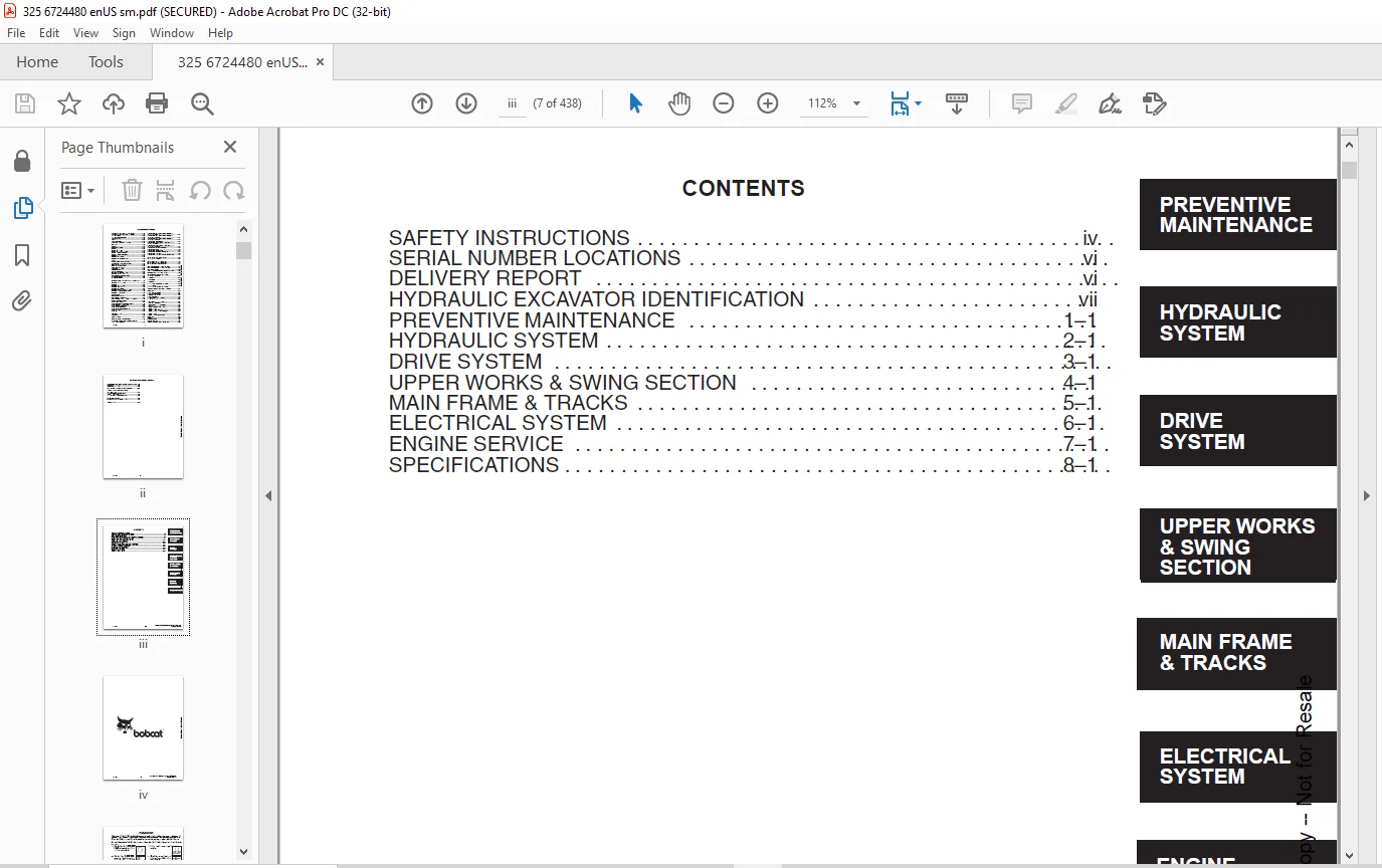
CONTENTS 7
FOREWORD 9
SAFETY INSTRUCTIONS 11
SERIAL NUMBER LOCATIONS 12
HYDRAULIC EXCAVATOR SERIAL NUMBER 12
ENGINE SERIAL NUMBER 12
DELIVERY REPORT 12
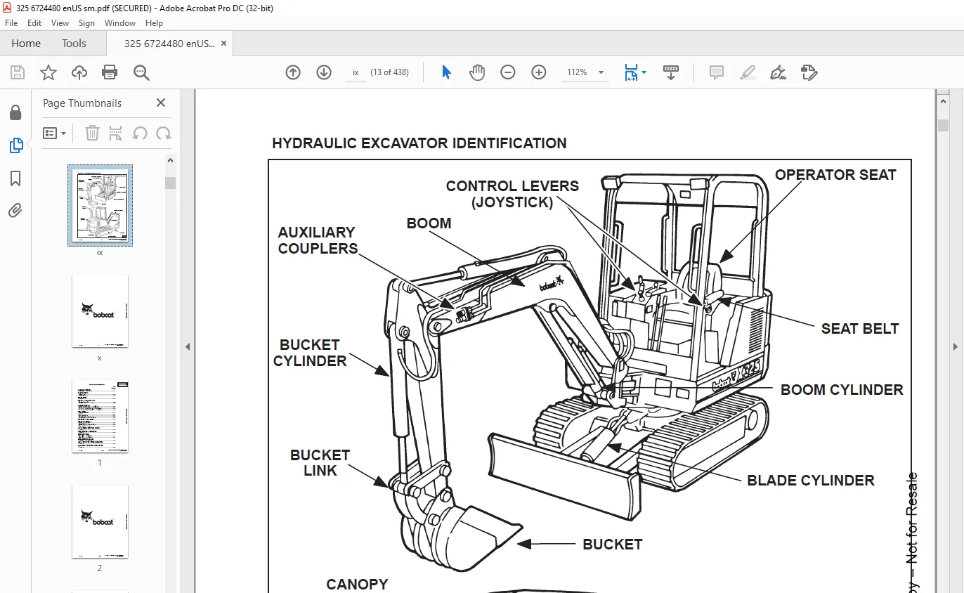
HYDRAULIC EXCAVATOR IDENTIFICATION 13
PREVENTIVE MAINTENANCE 15
SERVICE SCHEDULE 17
LIFTING AND BLOCKING THE EXCAVATOR 19
Procedure 19
TRANSPORTING THE HYDRAULIC EXCAVATOR 20
Procedure 20
ENGINE COVER 21
Procedure 21
AIR CLEANER SERVICE 21
Replacing the Filter Element 21
FUEL SYSTEM 23
Fuel Specifications 23
Filling the Fuel Tank 23
Fuel System Maintenance 24
Fuel Filter 24
Removing Air From the Fuel System 24
ENGINE LUBRICATION SYSTEM 25
Checking Engine Oil 25
Engine Oil and Filter Replacement 25
COOLING SYSTEM 26
Coolant Level 26
Coolant Replacement 26
Propylene Glycol (Factory Installed) 26
HYDRAULIC SYSTEM 27
Checking and Adding Fluid 27
Return Line Filter Service 27
Replacement of the Hydraulic Filter 27
Hydraulic Reservoir 28
USING A BOOSTER BATTERY (Jump Starting) 29
Procedure 29
LUBRICATION OF THE HYDRAULIC EXCAVATOR 30
FINAL DRIVE CASE 33
Checking Oil Level (S/N 12999 & Below) 33
Draining Final Drive Case (S/N 12999 & Below) 33
Checking Oil Level (S/N 13001 & Above) 34
Draining Final Drive Case (S/N 13001 & Above) 34
HEATER AIR FILTER SERVICE 34
SPARK ARRESTOR MUFFLER 35
Cleaning Spark Arrestor Muffler 35
HYDRAULIC SECTION 37
HYDRAULIC SCHEMATICS 41
HYDRAULIC SYSTEM TROUBLESHOOTING 49
HYDRAULIC SERVICE INFORMATION 54
Checking the Main Relief Valves (S/N 11001–12999) 54
Checking the Main Relief Valves (S/N 13001 & Above) 55
Testing the 4050 PSI (27925 kPa) Circuit Relief Valve 56
Testing the Auxiliary and Bucket Circuit Relief Valve 57
Testing the Left Hand Travel Circuit Relief Valve 58
Testing the Right Hand Travel Circuit Relief Valve 59
Testing the Boom Circuit Relief Valve 60
Checking the Hydraulic Pump 61
HYDRAULIC PUMP 62
Removal and Installation 62
Parts Identification 63
Disassembly 64
Assembly 66
HYDRAULIC CONTROL VALVE (6 Spool) HUSCO VALVE (S/N 11001–12999) 69
Removal and Installation 69
Parts Identification 70
Disassembly 71
Inlet Section 72
Right Hand & Left Hand Travel 73
Disassembly 73
Assembly 74
Boom, Bucket & Arm 76
Disassembly 76
Assembly 77
Port Relief Valves (Adjustable) 83
Auxiliary 79
Disassembly 79
Assembly 80
Port Relief Valves (Adjustable) 83
Parts Identification 83
Port Relief Valve Pressure Setting 84
Disassembly 84
Assembly 85
Adjustment Procedure 85
Main Relief Valves 86
Parts Identification 86
Disassembly 87
Assembly 87
Adjusting the Main Relief Valves 88
HYDRAULIC CONTROL VALVE (3 Spool) HUSCO VALVE (S/N 11001 –12999) 89
Description 89
Removal and Installation 89
Parts Identification 90
Disassembly 91
Blade and Boom Swing 92
Disassembly 92
Assembly 94
Lockout Valve Assembly 95
Disassembly 95
Assembly 96
Swing Motor Valve 97
Disassembly 97
Assembly 98
Build–Up Valve 101
Disassembly 101
Assembly 101
Test Procedure 102
HYDRAULIC CONTROL VALVE (5–Spool) HUSCO VALVE (S/N 13001 & Above) 103
Left Travel, Right Travel, Boom, Bucket and Auxiliary 103
Description 103
Removal and Installation 103
Parts Identification 104
Disassembly 105
Outlet Sections Disassembly 106
Outlet Sections Assembly 106
Mid Inlet Section Disassembly 106
Mid Inlet Section Assembly 106
Left Travel, Right Travel and Auxiliary Disassembly 107
Left Travel, Right Travel and Auxiliary Assembly 109
Boom and Bucket Disassembly 111
Boom and Bucket Assembly 113
Assembly 115
PORT RELIEF VALVES AND MAIN RELIEF VALVES (S/N 13001 & Above) 116
Parts Identification 116
Port Relief Valve Pressure Setting 117
Disassembly 117
Assembly 118
MAIN RELIEF VALVES (Adjustable) (S/N 13001 & Above) 119
Parts Identification 119
Assembly 120
Disassembly 121
Assembly 121
Adjusting the Main Relief Valves 122
HYDRAULIC CONTROL VALVE (5–Spool) HUSCO VALVE (S/N 13001 & Above) 123
Boost, Arm, Boom Swing, Blade and Swing Section 123
Description 123
Removal and Installation 123
Parts Identification 124
Disassembly 125
Inlet Section 126
Arm, Boost and Swing Motor Disassembly 127
Arm, Boost and Swing Motor Assembly 129
Boom Swing Disassembly 131
Boom Swing Assembly 133
Blade Disassembly 136
Blade Assembly 138
Assembly 140
ACCUMULATOR (S/N 11001 – 12999) 141
Pressure Reducing Valve 141
Description 141
Test Procedure 141
Removal and Installation 141
Parts Identification 142
Disassembly 143
Assembly 147
Charging 151
Setting the Safety Relief Valve 152
ACCUMULATOR (S/N 13001 & Above) 153
Removal and Installation 153
Parts Identification 154
PORT BLOCK 155
Removal and Installation (S/N 11001–12999) 155
Removal and Installation (S/N 13001 & Above) 155
AUXILIARY SELECTOR VALVE 156
Removal and Installation (S/N 11001–12999) 156
Removal and Installation (S/N 13001 & Above) 156
Disassembly and Assembly 156
TWO SPEED VALVE (S/N 13001 & Above) 157
Removal and Installation 157
OIL COOLER 158
Removal and Installation 158
HYDRAULIC RESERVOIR 159
Removal and Installation 159
HYDRAULIC FILTER ASSEMBLY 161
Removal and Installation 161
RETURN LINE FILTER 161
Removal and Installation 161
BOOM CYLINDER 162
Removal and Installation 162
BOOM CYLINDER SHIELD 162
Removal and Installation 162
ARM CYLINDER 163
Removal and Installation 163
BUCKET CYLINDER 164
Removal and Installation 164
BLADE CYLINDER 165
Removal and Installation 165
BOOM SWING CYLINDER 166
Removal and Installation 166
HYDRAULIC CYLINDERS 167
Disassembly 167
Assembly 169
JOYSTICK CONTROL CHANGE 174
ISO to STANDARD Control Pattern (S/N 12999 & Below) 174
STANDARD to ISO Control Pattern (S/N 12999 & Below) 174
ISO to STANDARD Control Pattern (S/N 13001 & Above) 175
STANDARD to ISO Control Pattern (S/N 13001 & Above) 175
DRIVE SECTION 176
LEFT CONSOLE (S/N 11001 – 12999) 178
Lockout Valve Removal and Installation 178
Cylinder Removal and Installation 178
Removal and Installation 179
LEFT CONSOLE (S/N 13001 & Above) 180
Control Lock Micro–Switch 180
Removal and Installation 180
Cylinder Removal and Installation 181
Removal and Installation 182
Release Handle 183
Removal and Installation 183
Disassembly and Assembly 184
Adjustment 184
Latch Plate 184
Adjustment 184
JOYSTICK (S/N 11001 –12999) 185
Left Joystick 185
Removal and Installation 185
Parts Identification 186
Right Joystick 187
Removal and Installation 187
Troubleshooting 187
Parts Identification 188
Disassembly and Assembly 189
JOYSTICK (S/N 13001 & Above ) 193
Removal and Installation 193
Parts Identification 194
Disassembly 196
Assembly 199
Troubleshooting 204
CONTROL LEVERS 205
Removal and Installation 205
Low Idle Adjustment 207
High Idle Adjustment 207
Speed Control Lever 207
Blade Lever 208
RIGHT CONSOLE 209
Removal and Installation (S/N 11001 –12999) 209
Removal and Installation (S/N 13001 & Above) 211
FOOT PEDALS AND STEERING LEVERS 213
Removal and Installation 213
Bushing Removal and Installation 214
UPPER WORKS AND SWING SECTION 216
REAR ENGINE COVER 218
Removal and Installation 218
SEAT AND MOUNTING FRAME 218
Removal and Installation 218
CENTER FLOOR PANEL 219
Removal and Installation 219
S/N 12999 & Below 220
S/N 13001 & Above 220
SWING MOTOR COVER 221
Removal and Installation 221
REAR FLOOR PANEL 221
Removal and Installation 221
TOOL BOX 221
Removal and Installation 221
LEFT SIDE COVER 221
Removal and Installation 221
CORNER POST 222
Removal and Installation 222
COUNTERWEIGHTS 223
Removal and Installation 223
FRONT ENGINE COVER 224
Removal and Installation 224
FUEL TANK 225
Removal and Installation 225
BUCKET 227
Removal and Installation 227
ARM 228
Removal and Installation 228
BOOM 229
Removal and Installation 229
BOOM SWING BRACKET 230
Removal 230
Installation 231
Hose Installation 232
SWING BRACKET BUSHING 233
Bushing Removal 233
Bushing Installation 233
SWING MOTOR 234
Removal and Installation 234
Parts Identification 235
Disassembly 236
Assembly 238
CROSS PORT RELIEF VALVE 243
Disassembly 243
Assembly 244
Description 245
Testing 245
SWING MOTOR DRIVE CARRIER 246
Removal and Installation 246
Parts Identification 246
Disassembly 247
Assembly 248
UPPERSTRUCTURE AND SWING CIRCLE GEAR 252
Removal and Installation 252
Swing Bearing Removal 253
Swing Bearing Installation 254
Alignment Pins (Threaded) 255
Alignment Pins (Not Threaded) 256
CENTER SWIVEL JOINT 257
Removal and Installation (Through Upper AccessCover) 257
Removal and Installation (Through Bottom Access Cover) (S/N 11001–12999) 257
Removal and Installation (Through Bottom Access Cover) (S/N 13001 & Above) 259
Parts Identification 260
Description 261
Disassembly 261
Assembly 262
ROPS CANOPY 265
Removal and Installation 265
CAB 267
Removal and Installation 267
Two Piece Side Window 269
Three Piece Side Windows 270
Door Removal and Installation 270
Front Window Removal and Installation 271
Front Lower Glass Removal and Installation 273
Front Upper Plexiglass Removal and Installation 273
Left Hand Side Glass Removal and Installation 273
Door Glass Removal and Installation 274
Rear Glass Removal and Installation 274
Right Hand Side Glass Removal and Installation 275
Two Piece Side Window 275
Three Piece Side Window 275
CAB/CANOPY REAR COVER 277
Removal 277
Installation 277
MAIN FRAME AND TRACKS 278
BLADE 280
Removal and Installation 280
TRACK 280
Track Lug Height 280
Track Tension 281
Rubber Tracks 281
Steel Tracks 282
Adjustment (S/N 11001–12999) 282
Adjustment (S/N 13001 & Above) 283
Removal and Installation 284
TRACK FRAME 288
Disassembly and Assembly (S/N 11001–12999) 288
Disassembly and Assembly (S/N 13001 & Above) 289
TRAVEL MOTOR 291
Testing 291
Removal and Installation (S/N 11001–12999) 292
Removal and Installation (S/N 13001 & Above) 293
Parts Identification (S/N 11001–12999) 295
Disassembly (S/N 11001–12999) 297
Assembly (S/N 11001–12999) 308
Check Oil Level (S/N 11001–12999) 318
Draining Final Drive Case (S/N 11001–12999) 318
TRAVEL MOTOR (SOM) 318
Checking Oil Level (S/N 13001 & Above) 319
Draining Final Drive Case (S/N 13001 & Above) 319
Parts Identification (S/N 13001 & Above) 320
Disassembly (S/N 13001 & Above) 321
Assembly (S/N 13001 & Above) 328
TRACK DAMAGE IDENTIFICATION 337
Cutting of Steel Cords 337
Abrasion of Embedded Metals 338
Separation of Embedded Metals 339
Separation of Embedded Metals Due To Corrosion 340
Cuts On The Lug Side Rubber 341
Cracks Of The Lug Side Rubber Due To Fatigue 342
Lug Abrasion 343
Cracks And Cuts On The Lug Side Rubber 343
Abrasion Of The Track Roller Side 344
Cuts On The Edges Of Track Roller Side 345
ELECTRICAL SYSTEM 346
ELECTRICAL SCHEMATICS 349
TROUBLESHOOTING 353
Chart 353
ELECTRICAL SYSTEM 353
Description 353
Fuses 354
Electrical System Service 354
BATTERY 355
Checking the Battery 355
Removal and Installation 355
ALTERNATOR 356
Belt Adjustment 356
Removal and Installation 356
Disassembly and Inspection 357
Stator Continuity Test 357
Stator Ground Test 357
Rotor Continuity Test 358
Rotor Ground Test 358
Rectifier Continuity (Diode) Test 358
Assembly 359
STARTER 360
Removal and Installation 360
Parts Identification 360
Disassembly and Assembly 361
Cleaning and Inspection 362
FUEL LEVEL SENDER 364
Removal and Installation 364
Checking 364
INSTRUMENT PANEL 365
Removal and Installation 365
GAUGES 365
Removal and Installation 365
GAUGE LIGHTS 366
Removal and Installation 366
CAB ELECTRICAL (Cab Option) 366
ENGINE SYSTEM 367
TROUBLESHOOTING 369
VALVE CLEARANCE 370
Adjustment 370
ENGINE COMPRESSION 370
Checking 370
FUEL SHUTOFF SOLENOID 372
Adjustment 372
Removal and Installation 372
Timer Module Removal and Installation 372
FUEL INJECTION PUMP 373
Checking the Injection Pump 373
Removal and Installation 373
Timing the Injection Pump 375
FUEL INJECTOR NOZZLES 377
Removal and Installation 377
Checking the Injector Nozzle 378
GLOW PLUGS 379
Removal and Installation 379
Checking the Glow Plug 379
FAN GUARD 380
Removal and Installation 380
RADIATOR 381
Removal and Installation 381
MUFFLER 382
Removal and Installation 382
AIR CLEANER 383
Removal and Installation 383
ENGINE 384
Removal and Installation 384
ENGINE FLYWHEEL 388
Removal and Installation 388
FLYWHEEL RING GEAR 389
CYLINDER HEAD 390
Removal and Installation 390
Disassembly and Assembly of the Cylinder Head 391
Servicing the Cylinder Head 392
Top Clearance 392
VALVE, VALVE SEAT AND GUIDE 393
Checking the Valve Guide 393
Reconditioning the Valve and Valve Seat 394
Valve Spring 395
ROCKER ARM AND SHAFT 395
Checking 395
TIMING GEARCASE COVER 396
Removal and Installation 396
IDLER GEAR AND CAMSHAFT 398
Removal and Installation 398
Servicing the Idler Gear and Shaft 400
TIMING GEARS 400
Checking Backlash 400
FUEL CAMSHAFT 401
Removal and Installation 401
Governor 401
CRANKSHAFT GEAR 402
Removal and Installation 402
OIL PUMP 402
Removal and Installation 402
Oil Pump Service 402
Checking Engine Oil Pressure 403
Relief Valve 403
PISTON AND CONNECTING ROD 404
Removal and Installation 404
Servicing the Piston and Connecting Rod 405
Connecting Rod Alignment 407
CRANKSHAFT AND BEARINGS 408
Removal and Installation 408
Servicing the Crankshaft and Bearings 409
CYLINDER BORE 412
Checking the Cylinder Bore 412
WATER PUMP 413
Disassembly and Assembly 413
SPECIFICATIONS 415
HYDRAULIC EXCAVATOR SPECIFICATIONS 417
Machine Dimensions 417
Lifting Capacity 418
HYDRAULIC SYSTEM 419
SWING SYSTEM 419
HYDRAULIC CYLINDERS 419
DRIVE SYSTEM 419
BRAKES 419
UNDERCARRIAGE 419
STD TRACK SHOES 419
CAPACITIES 419
DIGGING FORCE 419
ENGINE SPECIFICATIONS 420
Fuel Injection Nozzles 420
Fuel Injection Pump 420
Cylinder Head 420
Valves 420
Valve Springs 420
Valve Timing 420
Rocker Arms 420
Camshaft 421
Tappet 421
Cylinders 421
Piston Rings 421
Pistons 421
Connecting Rod 421
Oil Pump 421
Crankshaft 421
Timing Gear 422
Thermostat 422
Engine Bolt Torque 422
Re–Grinding The Crankshaft 423
FUEL, COOLANT AND LUBRICANTS CHART 424
ENGINE OIL SPECIFICATIONS 424
Description 424
Ethylene Glycol 424
Propylene Glycol 424
BUCKET SPECIFICATIONS 425
DECIMAL AND MILLIMETER EQUIVALENTS 426
U S TO METRIC CONVERSION 426
SERVICE MANUAL REVISION 427
325-1 427
325-2 429
325-3 431
325-4 433
325-5 435
325-6 437
IMAGES PREVIEW OF THE MANUAL:
Customer Support: [email protected]
https://vimeo.com/840703693?share=copy
PLEASE NOTE:
- This is the same manual used by the dealers to diagnose and troubleshoot your vehicle
- You will be directed to the download page as soon as the purchase is completed. The whole payment and downloading process will take anywhere between 2-5 minutes
- Need any other service / repair / parts manual, please feel free to contact [email protected] . We still have 50,000 manuals unlisted
S.M