Bobcat Excavator X331 X331E X334 Service Manual 6900464 (6-12) – PDF DOWNLOAD
$30.95
Bobcat Excavator X331 X331E X334 Service Manual 6900464 (6-12) – PDF DOWNLOAD
331 (S/N 512913001 & Above)
331E (S/N 517711001 & Above)
334 (S/N 516711001 & Above)
Description
Bobcat Excavator X331 X331E X334 Service Manual 6900464 (6-12) – PDF DOWNLOAD
FILE DETAILS:
Bobcat Excavator X331 X331E X334 Service Manual 6900464 (6-12) – PDF DOWNLOAD
Language : English
Pages : 534
Downloadable : Yes
File Type : PDF
Size:14.2 MB
DESCRIPTION:
Bobcat Excavator X331 X331E X334 Service Manual 6900464 (6-12) – PDF DOWNLOAD
FOREWORD
This manual is for the Bobcat excavator mechanic. It provides necessary servicing and adjustment procedures for the Bobcat excavator and its component parts and systems. Refer to the Operation & Maintenance Manual for operating instructions, starting procedure, daily checks, etc.
SAFETY INSTRUCTIONS
Instructions are necessary before operating or servicing machine. Read and understand the Operation & Maintenance Manual, Operator’s Handbook and signs (decals) on machine. Follow warnings and instructions in the manuals when making repairs, adjustments or servicing. Check for correct function after adjustments, repairs or service. Untrained operators and failure to follow instructions can cause injury or death.
The following publications provide information on the safe use and maintenance of the Bobcat machine and attachments:
- The Delivery Report is used to assure that complete instructions have been given to the new owner and that the machine is in safe operating condition.
- The Operation & Maintenance Manual delivered with the machine or attachment contains operating information as well as routine maintenance and service procedures. It is a part of the machine and can be stored in a container provided on the machine. Replacement Operation & Maintenance Manuals can be ordered from your Bobcat dealer.
- Machine signs (decals) instruct on the safe operation and care of your Bobcat machine or attachment. The signs and their locations are shown in the Operation & Maintenance Manual. Replacement signs are available from your Bobcat dealer.
- An Operator’s Handbook fastened to the operator cab. It’s brief instructions are convenient to the operator. The handbook is available from your dealer in an English edition or one of many other languages. See your Bobcat dealer for more information on translated versions.
- The AEM Safety Manual delivered with the machine gives general safety information.
- The Service Manual and Parts Manual are available from your dealer for use by mechanics to do shoptype service and repair work.
IMAGES PREVIEW OF THE MANUAL:
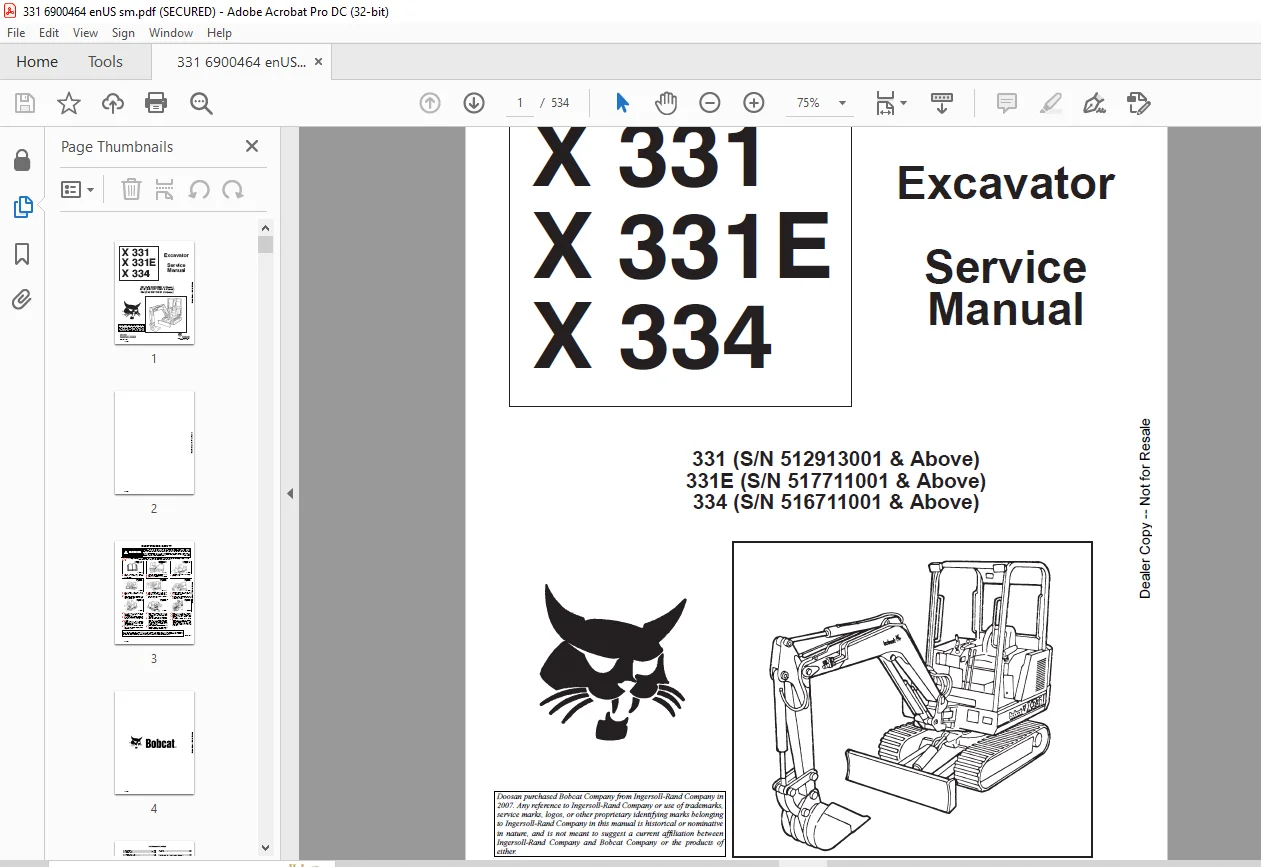
TABLE OF CONTENTS:
Bobcat Excavator X331 X331E X334 Service Manual 6900464 (6-12) – PDF DOWNLOAD
MAINTENANCE SAFETY 3
ALPHABETICAL INDEX 5
CONTENTS 7
FOREWORD 9
SERIAL NUMBER LOCATIONS 12
HYDRAULIC EXCAVATOR SERIAL NUMBER 12
ENGINE SERIAL NUMBER 12
DELIVERY REPORT 12
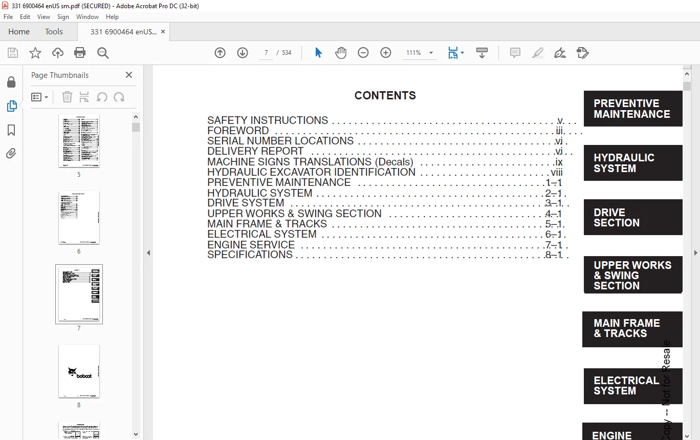
HYDRAULIC EXCAVATOR IDENTIFICATION 13
PREVENTIVE MAINTENANCE 15
SERVICE SCHEDULE (331 S/N 512913001–512915199) 17
SERVICE SCHEDULE (331 S/N 512915200 & Above),(331E 517711001 & Above) & (334 S/N 516711001 & Above) 18
LIFTING AND BLOCKING THE EXCAVATOR 19
Procedure 19
TRANSPORTING THE EXCAVATOR 20
Procedure 20
ENGINE COVER 21
Opening The Engine Cover 21
Adjustment Of The Engine Cover Latch 21
AIR CLEANER 22
Air Cleaner Service 22
FUEL SYSTEM 23
Fuel Specification 23
Filling The Fuel Tank 23
Fuel System Maintenance (331 S/N 512913001–512915199) 24
Fuel Filter (331 S/N 512913001–512915199) 24
Removing Air From The Fuel System (331 S/N 512913001–512915199) 24
Fuel System Maintenance (331 S/N 512915200 &Above), (331E S/N 517711001 & Above) & (334 S/N 516711001 & Above) 25
Fuel Filter (331 S/N 512915200 & Above), (331E S/N517711001 & Above) & (334 S/N 516711001 & Above) 25
Removing Air From The Fuel System (331 S/N512915200 & Above), (331E S/N 517711001 & Above)& (334 S/N 516711001 & Above) 25
ENGINE LUBRICATION SYSTEM 26
Checking Engine Oil 26
Replacement Of Oil And Filter 26
COOLING SYSTEM 27
Coolant Level 27
Coolant Replacement 27
ALTERNATOR BELT 28
Adjustment 28
ELECTRICAL SYSTEM 29
Using A Booster Battery (Jump Starting) 29
HYDRAULIC SYSTEM 30
Checking And Adding Fluid 30
Replacing The Hydraulic Oil 31
Replacing The Hydraulic Filter 31
Replacing The Drain Line Filter 31
SPARK ARRESTOR MUFFLER 32
Cleaning The Spark Arrestor Muffler (331 S/N 512913001–512915199) 32
Cleaning The Spark Arrestor Muffler (331 S/N512915200 & Above), (331E S/N 517711001 & Above)& (334 S/N 516711001 & Above) 33
TRAVEL MOTOR 34
Checking The Oil Level (331 S/N 512913001–512913404) 34
Draining And Refilling (331 S/N 512913001–512913404) 34
Checking The Oil Level (331 S/N 512913405 & Above),(331E S/N 517711001 & Above) & (334 S/N 516711001& Above) 34
Draining And Refilling (331 S/N 512913405 & Above),(331E S/N 517711001 & Above) & (334 S/N 516711001& Above) 34
LUBRICATION OF THE HYDRAULIC EXCAVATOR 35
Procedure 35
HEATER AIR FILTER (With Cab Option Only) (331 S/N512913001–512915199) 38
Service 38
HEATER AIR FILTER (With Cab Option Only) (331 S/N512915200 & Above), (331E S/N 517711001 & Above)& (334 S/N 516711001 & Above) 38
Service 38
HYDRAULIC SECTION 39
HYDRAULIC SCHEMATICS 43
HYDRAULIC SYSTEM TROUBLESHOOTING 69
HYDRAULIC SERVICE INFORMATION 74
Description 74
MAIN RELIEF VALVES (Adjustable) 74
Checking The Main Relief Valves 74
Testing the Blade, Boom Swing, Arm and Boost Circuit Relief Valves 74
Testing the Swing Circuit Relief 75
Testing The Auxiliary And Bucket Circuit Relief Valve 76
Testing The Left Hand Travel Circuit Relief Valve 77
Testing The Right Hand Travel Circuit Relief Valve 78
Testing The Boom Circuit Relief Valve 80
CROSS PORT RELIEF VALVE 81
Description 81
Testing 81
HYDRAULIC PUMP 82
Checking the Hydraulic Pump 82
Removal And Installation (331 S/N 512913001–512915199) 83
Parts Identification (331 S/N 512913001–512915199) 84
Removal And Installation (331 S/N 512915200 &Above), (331E S/N 517711001 & Above) & (334 S/N516711001 & Above) 85
Disassembly (331 S/N 512913001–512915199) 87
Assembly (331 S/N 512913001–512915199) 89
HYDRAULIC CONTROL VALVE (5–Spool) 92
Left Travel, Right Travel, Boom, Bucket And Auxiliary 92
Removal And Installation (331 S/N 512913001–512915199) 92
Removal And Installation (331 S/N 512915200 &Above), (331E S/N 517711001 & Above) & (334 S/N516711001 & Above) 93
Parts Identification 96
Disassembly 97
Outlet Sections Disassembly 98
Outlet Sections Assembly 98
Mid Inlet Section Disassembly 98
Mid Inlet Section Assembly 98
Left Travel, Right Travel and Auxiliary Disassembly 99
Left Travel, Right Travel and Auxiliary Assembly 101
Boom And Bucket Disassembly 103
Boom And Bucket Assembly 105
Assembly 107
PORT RELIEF VALVES AND MAIN RELIEF VALVES 108
Parts Identification 108
Port Relief Valve Pressure Setting 109
Disassembly 109
Assembly 110
Adjustment Procedure (Work Port Relief Valves Only) 110
MAIN RELIEF VALVES (Adjustable) 111
Parts Identification 111
Pressure Settings 112
Disassembly 113
Assembly 113
Adjusting The Main Relief Valves 114
HYDRAULIC CONTROL VALVE (5–Spool) 115
Boost, Arm, Boom Swing, Blade And Swing Section 115
Description 115
Removal And Installation 115
Parts Identification 116
Disassembly 117
Inlet Section Disassembly And Assembly 118
Arm, Boost And Swing Motor Disassembly 119
Arm, Boost And Swing Motor Assembly 121
Boom Swing Disassembly 123
Boom Swing Assembly 125
Blade Disassembly 128
Blade Assembly 130
Assembly 132
ACCUMULATOR / PRESSURE REDUCING VALVE (S/N 512913001 – 512918775, 517711001 – 517711159,516711001 – 516711880) 133
Description 133
Removal And Installation 133
Parts Identification 134
Disassembly 135
Assembly 137
ACCUMULATOR / PRESSURE REDUCING VALVE(S/N 512918776 & Above, 517711160 & Above and516711881 & Above) 140
Parts Identification 140
Disassembly 141
Assembly 143
ACCUMULATOR / PRESSURE REDUCING VALVE (For All Serial Numbers) 146
Testing 146
BUILD UP VALVE 148
Description 148
Removal And Installation 148
Disassembly And Assembly 148
AUXILIARY SELECTOR VALVE 149
Removal And Installation (331 S/N 512913001–512915199) 149
Removal And Installation (331 S/N 512915200 &Above), 331E S/N 517711001 & Above) & (334 S/N 516711001 & Above) 149
Disassembly And Assembly 151
Port Block 152
Removal And Installation 152
OIL COOLER 153
Removal And Installation 153
HYDRAULIC RESERVOIR AND FUEL RESERVOIR 154
Removal And Installation 154
HYDRAULIC FILTER ASSEMBLY 158
Removal And Installation 158
BOOM CYLINDER 159
Removal And Installation 159
Parts Identification 160
ARM CYLINDER 161
Removal And Installation 161
Parts Identification 162
BUCKET CYLINDER 163
Removal And Installation (Standard And Long Arm) 163
Removal And Installation (Extendible Arm) 164
Parts Identification 166
BLADE CYLINDER 167
Removal And Installation 167
Parts Identification 168
BOOM SWING CYLINDER 169
Removal And Installation 169
Parts Identification 170
EXTENDIBLE ARM CYLINDER 171
Removal And Installation 171
HYDRAULIC CYLINDER 173
Disassembly 173
Assembly 175
JOYSTICK CONTROL CHANGE (331 S/N512913001–512917112 & 334 S/N 516711001–516711270) 180
ISO to STANDARD Control Pattern 180
STANDARD To ISO Control Pattern 180
DRIVE SECTION 181
RIGHT CONSOLE COVER (331 S/N 512913001–512915199) 183
Removal And Installation 183
RIGHT CONSOLE (331 S/N 512913001– 512915199) 185
Removal And Installation 185
Speed Control Lever Removal And Installation 187
Speed Control Lever Adjustment 187
Low Speed Position 187
High Speed Position 187
Blade Control Lever And Cable Removal AndInstallation 188
LEFT CONSOLE (331 S/N 512913001– 512915199) 189
Control Lock Micro–Switch Removal And Installation 189
Gas Spring Removal And Installation 190
Removal And Installation 190
Lock Lever Removal And Installation 192
Lock Lever Adjustment 193
Latch Plate Adjustment 193
RIGHT CONSOLE COVER (331 S/N 512915200 &Above), (331E S/N 517711001 & Above) & (334 S/N 516711001 & Above) 194
Removal And Installation 194
Arm Rest Removal And Installation 195
Gauge Removal And Installation 195
RIGHT CONSOLE (331 S/N 512915200 & Above),(331E S/N 517711001 & Above) & (334 S/N 516711001& Above) 196
Swing Lock Lever Removal And Installation 196
Blade Lever Removal And Installation 198
Speed Control Lever Removal And Installation 199
Speed Control Lever Adjustment 201
LEFT CONSOLE COVER (331 S/N 512915200 &Above), (331E S/N 517711001 & Above) & (334 S/N 516711001 & Above) 202
Removal And Installation 202
Arm Rest Removal And Installation 203
Switch Removal And Installation 203
Switch Description 203
Rear Cover Removal And Installation 204
Heater Control Removal And Installation 204
LEFT CONSOLE (331 S/N 512915200 & Above), (331ES/N 517711001 & Above) & (334 S/N 516711001 &Above) 205
Console And Mount Removal And Installation 205
Control Lock Micro–switch Removal And Installation 206
Lock Lever Removal And Installation 207
Gas Spring Removal And Installation 209
Console Removal And Installation 210
JOYSTICK 212
Removal And Installation (331 S/N 512913001–512915199) 212
Removal And Installation Of Right Hand Joystick(331 S/N 512915200 & Above), (331E S/N 517711001 & Above) & (334 S/N 516711001 & Above) 213
Removal And Installation Of Left Hand Joystick (331S/N 512915200 & Above), (331E S/N 517711001 & Above) & (334 S/N 516711001 & Above) 213
Troubleshooting 214
Parts Identification 215
Disassembly 216
Assembly 221
STEERING LEVERS AND PEDALS 226
Removal And Installation 226
Adjusting Linkage Rods 227
UPPER WORKS AND SWING SECTION 229
ENGINE COVER 233
Removal And Installation 233
SEAT AND SEAT MOUNT 235
Removal And Installation (331 S/N 512913001–512915199) 235
Removal And Installation (331 S/N 512915200 &Above) (331E S/N 517711001 & Above) & (334 S/N 516711001 & Above) 236
FLOORMAT AND FLOOR PLATE 237
Removal And Installation 237
REAR FLOOR PLATE 239
Removal And Installation (331 S/N 512913001–512915199) 239
SWING MOTOR COVER 239
Removal And Installation 239
TOOL BOX 240
Removal And Installation (331 S/N 512913001–512915199) 240
Removal And Installation (331 S/N 512915200 &Above), (331E S/N 517711001 & Above) & (334 S/N 516711001 & Above) 240
LEFT HAND SIDE COVER 241
Removal And Installation (331 S/N 512913001–512915199) 241
Removal And Installation (331 S/N 512915200 &Above), (331E S/N 517711001 & Above) & (334 S/N 516711001 & Above) 241
RIGHT HAND SIDE COVER 242
Removal And Installation 242
RIGHT HAND CORNER POST 243
Removal And Installation 243
LEFT HAND CORNER POST 243
Removal And Installation 243
COUNTERWEIGHTS 244
Removal And Installation 244
FRONT ENGINE COVER 245
Removal And Installation 245
BUCKET (PIN ON) 246
Removal And Installation 246
BUCKET TEETH 246
Removal And Installation 246
X–CHANGE™ 247
Removal And Installation 247
Disassembly 249
Assembly 253
EXTENDIBLE ARM 258
Removal And Installation 258
Disassembly And Assembly 261
ARM 262
Removal And Installation 262
ARM BUSHINGS 262
Arm To Boom Bushing Removal And Installation 262
Arm To Bucket And Bucket Link Removal And Installation 263
BOOM 264
Removal And Installation 264
BOOM BUSHING 265
Removal And Installation 265
BOOM SWING BRACKET 266
Removal And Installation 266
Hose Installation 269
SWING BRACKET BUSHING 270
Bushing Removal 270
Bushing Installation 270
BOOM PIVOT BUSHING 271
Bushing Removal 271
Bushing Installation 271
SWING MOTOR 272
Removal And Installation (331 S/N 512913001–512915199) 272
Removal And Installation (331 S/N 512915200 &Above), (331E S/N 517711001 & Above) & (334 S/N 516711001 & Above) 273
Cross Port Relief Valve Parts Identification 274
Cross Port Relief Valve Disassembly 275
Cross Port Relief Valve Assembly 277
Parts Identification 279
Disassembly 280
Assembly 283
SWING MOTOR DRIVE CARRIER 287
Removal And Installation 287
Parts Identification 287
Disassembly 288
Assembly 289
UPPERSTRUCTURE AND SWING CIRCLE GEAR 293
Removal And Installation 293
Swing Bearing Removal 294
Swing Bearing Installation 295
Alignment Pins (Not Threaded) 297
CENTER SWIVEL JOINT 298
Removal And Installation 298
Parts Identification 299
Disassembly 300
Assembly 301
ROPS CANOPY 304
Removal And Installation 304
CAB 306
Removal And Installation 306
Heater Removal And Installation (331 S/N512913001– 512915199) 308
Heater Removal And Installation (331 S/N 512915200& Above), (331E S/N 517711001 & Above) & (334 S/N516711001 & Above) 309
Heater Disassembly And Assembly (331 S/N512915200 & Above), (331E S/N 517711001 & Above)& (334 S/N 516711001 & Above) 311
Front Window Removal And Installation 314
Front Lower Window Removal And Installation 315
Front Upper Window Removal And Installation (331S/N 512913001–512915199) 316
Front Upper Window Removal And Installation (331S/N 512915200 & Above), (331E S/N 517711001 &Above) & (334 S/N 516711001 & Above) 316
Door Removal And Installation 316
Door Window Removal And Installation 317
Left Hand Side Window Removal And Installation 317
Right Hand Side Window Removal And Installation 318
Right Hand Window Assembly Removal And Installation 319
Rear Window Removal And Installation 319
CAB/CANOPY REAR COVER 320
Removal 320
Installation 320
MAIN FRAME AND TRACKS 321
BLADE 323
Removal And Installation 323
TRACK 323
Track Lug Height 323
Track Tension Adjustment 324
Rubber Track Clearance 324
Steel Track Clearance 325
Adjustment 326
Rubber Track Removal And Installation 327
Steel Track Removal And Installation 329
TRACK FRAME 331
Disassembly And Assembly 331
Recoil Spring Disassembly And Assembly 333
TRACK IDLER 334
Parts Identification 334
Disassembly 335
Assembly 337
TRACK ROLLER 341
Parts Identification 341
Disassembly 342
Assembly 344
TRAVEL MOTOR 348
Testing (331 S/N 512913001–512913404) 348
Removal And Installation 349
Parts Identification (331 S/N 512913001–512913404) 350
Disassembly (331 S/N 512913001–512913404) 351
Assembly (331 S/N 512913001–512913404) 366
Parts Identification (331 S/N 512913405 & Above),(331E S/N 517711001 & Above)(334 S/N 516711001 &Above) 380
Disassembly (331 S/N 512913405 & Above), (331E S/N517711001 & Above) & (334 S/N 516711001 & Above) 381
Assembly (331 S/N 512913405 & Above), (331E S/N517711001 & Above) & (334 S/N 516711001 & Above 390
TRACK DAMAGE IDENTIFICATION 401
Cutting Of Steel Cords 401
Abrasion Of Embedded Metals 402
Separation Of Embedded Metals 403
Separation Of Embedded Metals Due To Corrosion 404
Cuts On The Lug Side Rubber 405
Cracks Of The Lug Side Rubber Due To Fatigue 406
Lug Abrasion 407
Abrasion Of The Track Roller Side 408
Cuts On The Edges Of Track Roller Side 409
ELECTRICAL SYSTEM 411
ELECTRICAL SCHEMATICS 413
TROUBLESHOOTING 423
ELECTRICAL SYSTEM 423
Description 423
Fuses (331 S/N 512913001–512915199) 424
Fuse Arrangement (331 S/N 512913001–512915199) 424
Electrical Relays And Diodes (S/N 512915200 &Above), (331E S/N 517711001 & Above) & (334 S/N 516711001 & Above) 424
Fuse Arrangement (331 S/N 512915200 & Above),(331E S/N 517711001 & Above) & (334 S/N 516711001& Above) 425
BATTERY 426
Removal And Installation 426
Servicing The Battery 427
ALTERNATOR 428
Belt Adjustment 428
Removal And Installation 428
Alternator Output Test 429
Rectifier (Diode) Test 429
Alternator Regulator Test 430
Parts Identification 431
Disassembly And Inspection 431
Stator Continuity Test 431
Stator Ground Test 431
Rotor Continuity Test 432
Rotor Ground Test 432
Rectifier Continuity (Diode) Test 432
Assembly 433
STARTER 434
Removal And Installation (331 S/N 512913001–512915199) 434
Removal And Installation (331 S/N 512915200 &Above), (331E S/N 517711001 & Above) & (334 S/N 516711001 & Above) 434
Disassembly And Assembly (331 S/N 512913001–512915199) 435
Cleaning And Inspection (331 S/N 512913001–512915199) 436
Parts Identification (331 S/N 512913001–512915199) 437
Parts Identification (331 S/N 512915200 & Above), (331E S/N 517711001 & Above) & (334 S/N 516711001 & Above) 438
Disassembly (331 S/N 512915200 & Above), (331E S/N517711001 & Above) & (334 S/N 516711001 & Above) 439
Inspection And Repair (331 S/N 512915200 & Above)& (334 S/N 516711001 & Above) 444
Assembly (331 S/N 512915200 & Above), (331E517711001 & Above) & (334 S/N 516711001 & Above) 447
FUEL LEVEL SENDER 452
Removal And Installation 452
Testing 452
INSTRUMENT PANEL (331 S/N 512913001–512915199) 453
Removal And Installation 453
GAUGES 453
Removal And Installation (331 S/N 512913001–512915199) 453
Bulb Replacement (331 S/N 512913001–512915199) 454
Removal And Installation (331 S/N 512915200 &Above), (331E S/N 517711001 & Above) & (334 S/N516711001 & Above) 455
Bulb Replacement (331 S/N 512915200 & Above),(331E S/N 517711001 & Above) & (334 S/N 516711001& Above) 455
TIMER (331 S/N 512915200 & Above), (331E S/N517711001 & Above) & (334 S/N 516711001 & Above) 456
Removal And Installation 456
DIODES (331 S/N 512915200 & Above), (331E S/N517711001 & Above) & (334 S/N 516711001 & Above) 456
Diode Location 456
Diode Replacement 456
Diode Testing 456
CAB ELECTRICAL 457
Cab Option (331 S/N 512913001–512915199) 457
Cab Option (331 S/N 512915200 & Above), (331E S/N517711001 & Above) & (334 S/N 516711001 & Above) 457
HORN 458
Removal And Installation 458
BUZZER 458
Removal And Installation 458
ENGINE SERVICE 459
TROUBLESHOOTING 461
Chart 461
VALVE CLEARANCE 462
Adjustment 462
ENGINE COMPRESSION 462
Checking 462
GLOW PLUGS 463
Removal And Installation 463
Checking The Glow Plug 463
FUEL SHUT–OFF SOLENOID 464
Adjustment 464
Removal And Installation 464
Timer Module Removal And Installation 464
FUEL INJECTION PUMP 465
Checking The Injection Pump 465
Removal And Installation 465
Timing The Injection Pump 467
FUEL INJECTOR NOZZLES 468
Removal And Installation 468
Checking The Injector Nozzle 469
FAN GUARD 470
Removal And Installation 470
RADIATOR 470
Removal And Installation 470
MUFFLER 472
Removal And Installation (331 S/N 512913001–512915199) 472
Removal And Installation (331 S/N 512915200 &Above), (331E S/N 517711001 & Above) & (334 S/N516711001 & Above) 472
AIR CLEANER 473
Removal And Installation (331 S/N 512913001–512915199) 473
Removal And Installation (331 S/N 512915200 &Above), (331E S/N 517711001 & Above) & (334 S/N516711001 & Above) 474
ENGINE 475
Removal And Installation 475
ENGINE FLYWHEEL 479
Removal And Installation (331 S/N 512913001–512915199) 479
Removal And Installation (331 S/N 512915200 &Above), (331E S/N 517711001 & Above) & (334 S/N 516711001 & Above) 480
Flywheel Ring Gear 481
CYLINDER HEAD 482
Removal And Installation 482
Disassembly And Assembly 483
Servicing The Cylinder Head 484
Top Clearance 484
VALVE, VALVE SEAT AND GUIDE 485
Checking The Valve Guide 485
Reconditioning The Valve And Valve Seat 486
Valve Spring 487
ROCKER ARM AND SHAFT 488
Checking 488
TIMING GEARCASE COVER 489
Removal And Installation 489
IDLER GEAR AND CAMSHAFT 491
Removal And Installation 491
Servicing The Camshaft 492
Servicing The Idler Gear And Shaft 493
TIMING GEARS 494
Checking Backlash 494
FUEL CAMSHAFT 495
Removal And Installation 495
Governor 495
CRANKSHAFT GEAR 496
Removal And Installation 496
OIL PUMP 496
Removal And Installation 496
Oil Pump Service 496
Checking Engine Oil Pressure 497
Relief Valve 497
PISTON AND CONNECTING ROD 498
Removal And Installation 498
Servicing The Piston And Connecting Rod 499
Connecting Rod Alignment 501
CRANKSHAFT AND BEARINGS 502
Removal And Installation 502
Servicing The Crankshaft And Bearings 503
CYLINDER BORE 507
Checking The Cylinder Bore 507
WATER PUMP 508
Removal And Installation 508
Disassembly And Assembly 508
SPECIFICATIONS 509
HYDRAULIC EXCAVATOR SPECIFICATIONS 511
Machine Dimensions (331 S/N 512913001 & Above) Standard Arm 511
Machine Dimensions (331E S/N 517711001 & Above) Extendible Arm 512
Machine Dimensions (334 S/N 516711001 & Above) Long Arm 513
Lifting Capacity 514
WEIGHTS 516
CONTROLS 516
ENGINE 516
ELECTRICAL 516
HYDRAULIC SYSTEM 516
CYLINDER CYCLE TIME 516
SWING SYSTEM 517
HYDRAULIC CYLINDERS 517
DRIVE SYSTEM 517
BRAKES 517
UNDERCARRIAGE 517
STD TRACK SHOES 517
REFILL CAPACITIES 517
DIGGING FORCE 517
ENGINE SPECIFICATIONS 518
Fuel Injection Nozzles 518
Fuel Injection Pump 518
Cylinder Head 518
Valves 518
Valve Springs 518
Valve Timing 518
Rocker Arms 518
Camshaft 519
Tappet 519
Piston Rings 519
Pistons 519
Connecting Rod 519
Oil Pump 519
Crankshaft 520
Timing Gear 520
Thermostat 520
Engine Bolt Torque 520
Crankshaft Re–Grind Data 521
Torque For General Metric Bolts 521
FUEL, COOLANT AND LUBRICANTS 522
ENGINE OIL SPECIFICATIONS 522
Description 522
ANTI–FREEZE SOLUTION 522
Propylene Glycol 522
DECIMAL AND MILLIMETER EQUIVALENTS 523
U S TO METRIC CONVERSION 523
SERVICE MANUAL REVISION 525
331-1 525
331/334-2 527
331/334-3 529
331/334-4 531
331/331E/334-5 533
Customer Support: [email protected]
https://vimeo.com/841863355?share=copy
PLEASE NOTE:
- This is the SAME exact manual used by your dealers to fix your vehicle.
- The same can be yours in the next 2-3 mins as you will be directed to the download page immediately after paying for the manual.
- Any queries / doubts regarding your purchase, please feel free to contact [email protected]
s.m