Bobcat Excavator X337 X331 Service Manual 6900380 (6-12) – PDF DOWNLOAD
$29.95
Bobcat Excavator X337 X331 Service Manual 6900380 (6-12) – PDF DOWNLOAD
337 (S/N 515411001 & Above)
341 (S/N 230611001 & Above)
Description
Bobcat Excavator X337 X331 Service Manual 6900380 (6-12) – PDF DOWNLOAD
FILE DETAILS:
Bobcat Excavator X337 X331 Service Manual 6900380 (6-12) – PDF DOWNLOAD
Language : English
Pages : 492
Downloadable : Yes
File Type : PDF
Size: 17.6 MB
DESCRIPTION:
Bobcat Excavator X337 X331 Service Manual 6900380 (6-12) – PDF DOWNLOAD
337 (S/N 515411001 & Above)
341 (S/N 230611001 & Above)
FOREWORD
This manual is for the Bobcat excavator mechanic. It provides necessary servicing and adjustment procedures for the Bobcat excavator and its component parts and systems. Refer to the Operation & Maintenance Manual for operating instructions, starting procedure, daily checks, etc.
SAFETY INSTRUCTIONS
Instructions are necessary before operating or servicing machine. Read and understand the Operation & Maintenance Manual, Operator’s Handbook and signs (decals) on machine. Follow warnings and instructions in the manuals when making repairs, adjustments or servicing. Check for correct function after adjustments, repairs or service. Untrained operators and failure to follow instructions can cause injury or death.
The following publications provide information on the safe use and maintenance of the Bobcat machine and attachments
TABLE OF CONTENTS:
Bobcat Excavator X337 X331 Service Manual 6900380 (6-12) – PDF DOWNLOAD
MAINTENANCE SAFETY 3
ALPHABETICAL INDEX 5
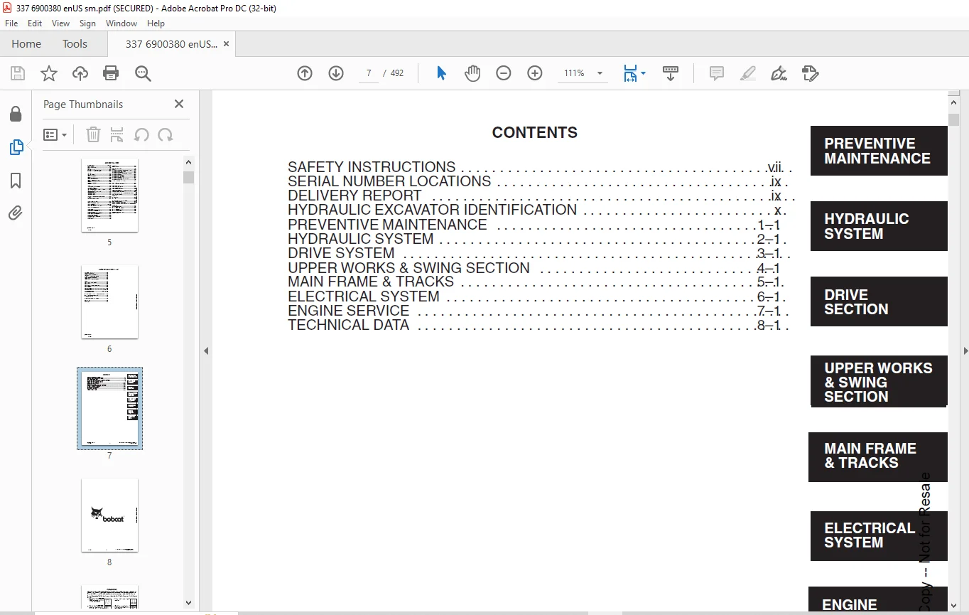
CONTENTS 7
FOREWORD 9
SAFETY INSTRUCTIONS 11
SERIAL NUMBER LOCATIONS 13
HYDRAULIC EXCAVATOR SERIAL NUMBER 13
ENGINE SERIAL NUMBER 13
DELIVERY REPORT 13
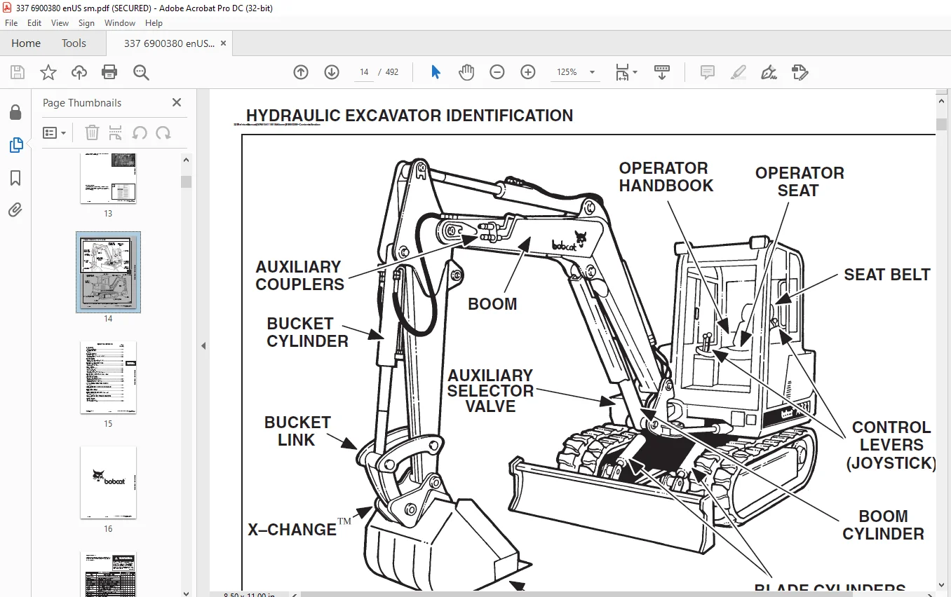
HYDRAULIC EXCAVATOR IDENTIFICATION 14
PREVENTIVE MAINTENANCE 15
SERVICE SCHEDULE 17
LIFTING AND BLOCKING THE EXCAVATOR 18
Procedure 18
TRANSPORTING THE HYDRAULIC EXCAVATOR 19
Procedure 19
ENGINE COVER 20
Opening The Engine Cover 20
Adjusting The Engine Cover Latches 20
AIR CLEANER 21
Air Cleaner Service 21
FUEL SYSTEM 22
Fuel Specifications 22
Filling The Fuel Tank 22
Fuel System Maintenance 22
Fuel Filter Service 23
Removing Air From The Fuel System 23
ENGINE LUBRICATION SYSTEM 24
Checking Engine Oil 24
Replacing Oil And Filter 24
COOLING SYSTEM 25
Coolant Level 25
Replacing Coolant 25
Propylene Glycol (Factory Installed) 25
ALTERNATOR BELT 26
Adjustment 26
HYDRAULIC SYSTEM 27
Checking And Adding Fluid 27
Replacing The Hydraulic Fluid 28
Replacing the Hydraulic Filter 29
Replacing The Case Drain Filter 30
SPARK ARRESTOR MUFFLER (If Equipped) 31
Cleaning Procedure 31
TRAVEL MOTOR 32
Checking Oil Level 32
Draining And Refilling 32
LUBRICATION OF THE HYDRAULIC EXCAVATOR 33
Procedure 33
HEATER AIR FILTER (With Cab Option Only) 36
Cleaning Procedure 36
HYDRAULIC SECTION 37
HYDRAULIC SCHEMATICS 41
HYDRAULIC SYSTEM TROUBLESHOOTING 46
HYDRAULIC SERVICE INFORMATION 51
Description 51
HYDRAULIC PUMPS 53
Testing The Hydraulic Gear Pump 53
Testing The Pump Stand By Circuit 55
Adjusting The Pump Stand By Circuit 55
Testing The Torque Limiter Load Sense Circuit 56
Testing The Pump Compensator 57
Adjusting The Pump Compensator 57
Testing The Torque Limiter For Pressure At Maximum Flow 58
Testing The Torque Limiter For Flow At Maximum Pressure 61
HYDRAULIC PISTON PUMP 62
Removal And Installation 62
Coupler Removal And Installation 63
Torque Limiter Valve Parts Identification 64
Torque Limiter Valve Removal 65
Torque Limiter Valve Disassembly 66
Torque Limiter Valve Assembly 69
Initial Torque Limiter Valve Setting 71
Torque Limiter Valve Installation 72
Parts Identification 73
Disassembly 74
Assembly 81
Pump Control Parts Identification 89
Pump Control Removal And Installation 90
Pump Control Disassembly 90
Pump Control Assembly 91
HYDRAULIC GEAR PUMP (S/N 515411001 –515412249 and 230611001 – 230611067) 93
Parts Identification 93
Disassembly 94
Assembly 96
HYDRAULIC GEAR PUMP 98
(S/N 515412250 & Above and 230611068 & Above) 98
Parts Identification 98
Disassembly 99
Assembly 101
MAIN RELIEF VALVES 104
Pressure Setting And Adjustment 104
Pressure Setting And Adjustment (3900 PSI) 105
Load Sense Relief Valve Setting (3450 PSI) (If Equipped) 105
Removal and Installation 106
PORT RELIEF VALVES 107
Port Relief Valve Pressure Setting 107
Parts Identification 107
Adjustment Procedure 108
HYDRAULIC CONTROL VALVE 109
Removal And Installation 109
Mid–Inlet Isolator Spool 112
Control Valve Identification 113
Disassembly and Assembly 114
Swing and Second Auxiliary Valve Section 120
Blade Valve Section 122
Mid–Inlet Valve Section 123
Load Sense Relief Valve Parts Identification 123
Boom Swing and Travel Valve Sections 124
Bucket, Arm, Boom and Auxiliary Valve Sections 126
PRESSURE REDUCING VALVE (With Accumulator) 128
Description 128
Removal And Installation 128
PRESSURE REDUCING VALVE (Without Accumulator) 130
Description 130
Removal And Installation 130
Parts Identification 131
Disassembly 132
Assembly 134
Testing 136
Testing (S/N 515411497 – 515412054 & 2306 11001–230611203) 137
Testing (S/N 515411496 & Below) 138
PRESSURE REDUCING VALVE (With and WithoutAccumulator) (S/N 515412053 & Above and 230611204 & Above) 139
Parts Identification 139
Disassembly 140
Assembly 142
Testing 144
Testing (With Accumulator) 145
Testing (Without Accumulator) 145
DUAL SEQUENCE VALVE 146
Removal and Installation 146
Disassembly and Assembly 146
AUXILIARY HYDRAULIC VALVE 147
Description 147
Removal And Installation 147
Foot Pedal Disassembly and Assembly (Later Model) 149
Foot Pedal Disassembly and Assembly (Early Model) 151
Disassembly 152
Assembly 154
BOOM SWING LOCK VALVE 156
Description 156
Removal And Installation 156
Parts Identification 156
Disassembly 157
Assembly 159
OIL COOLER 164
Removal And Installation 164
HYDRAULIC RESERVOIR 165
Removal And Installation 165
LIFTING CLAMP CYLINDER (If Equipped) 167
Removal And Installation 167
BOOM CYLINDER 168
Removal And Installation 168
Parts Identification 170
ARM CYLINDER 171
Removal And Installation 171
Parts Identification 172
BUCKET CYLINDER 173
Removal And Installation 173
Parts Identification 174
BLADE CYLINDER 175
Removal And Installation 175
Parts Identification 176
BOOM SWING CYLINDER 177
Removal And Installation 177
Parts Identification 178
HYDRAULIC CYLINDER 179
Disassembly 179
Assembly 181
JOYSTICK CONTROL CHANGE 186
ISO/Standard Control Pattern 186
CONTROL PATTERN SELECTOR VALVE 187
Disassembly 187
Assembly 188
AUXILIARY SELECTOR VALVE 189
Description 189
Removal And Installation 189
Disassembly And Assembly 190
DRIVE SECTION 192
RIGHT CONSOLE COVER 194
Removal And Installation 194
Arm Rest Removal And Installation 195
Gauge Removal And Installation 195
RIGHT CONSOLE 196
Swing Lock Lever Removal And Installation 196
Blade Lever Removal And Installation 198
Speed Control Lever Removal And Installation 199
Speed Control Lever Adjustment 201
LEFT CONSOLE COVER 202
Removal And Installation 202
Arm Rest Removal And Installation 203
Switch Removal And Installation 203
Rear Cover Removal And Installation 204
Heater Control Removal And Installation 204
LEFT CONSOLE 205
Console And Mount Removal And Installation 205
Control Lock Micro–switch Removal And Installation 206
Lock Lever Removal And Installation 207
Gas Spring Removal And Installation 209
Console Removal And Installation 210
JOYSTICK 212
Removal And Installation Of Right Hand Joystick 212
Removal And Installation Of Left Hand Joystick 212
Parts Identification 213
Disassembly 214
Assembly 218
Troubleshooting 224
STEERING LEVERS AND PEDALS 225
Removal And Installation 225
Adjusting The Linkage Cables 226
Disassembly And Assembly 226
AUXILIARY HYDRAULIC VALVE 227
Removal And Installation 227
UPPER WORKS AND SWING SECTION 228
ENGINE COVER 230
Removal And Installation 230
SEAT AND SEAT MOUNT 232
Removal And Installation 232
FLOORMAT AND FLOOR PLATE 233
Removal And Installation 233
REAR FLOOR PLATE 234
Removal And Installation 234
LEFT SIDE COVER 235
Removal And Installation 235
RIGHT SIDE COVER 235
Removal And Installation 235
RIGHT CORNER POST 236
Removal And Installation 236
LEFT CORNER POST 236
Removal And Installation 236
RIGHT COUNTERWEIGHT 237
Removal And Installation 237
LEFT COUNTERWEIGHT 238
Removal And Installation 238
BATTERY BOX 240
Removal And Installation 240
FUEL TANK 241
Removal And Installation 241
BUCKET TEETH 243
Removal And Installation 243
X–CHANGE™ 244
Removal And Installation 244
ARM 245
Removal And Installation 245
BOOM 246
Removal And Installation 246
BOOM SWING BRACKET 247
Removal And Installation 247
Hose Installation 251
SWING BRACKET BUSHING 252
Bushing Removal 252
Bushing Installation 252
SWING MOTOR (S/N 515411496 & Below) 253
Removal And Installation 253
Parts Identification 255
Disassembly 256
Inspection 259
Assembly 260
SWING MOTOR DRIVE CARRIER (S/N 515411496 &Below) 264
Removal And Installation 264
Parts Identification 266
Disassembly 267
Assembly 268
SWING MOTOR/BRAKE ASSEMBLY (S/N 515411497& Above) 270
Removal And Installation 270
SWING MOTOR/BRAKE ASSEMBLY (S/N 515411497& Above) 273
Disassembly 273
Inspection 277
Assembly 278
SWING MOTOR DRIVE CARRIER (S/N 515411497 &Above) 283
Removal And Installation 283
Parts Identification 284
Checking The Drive Carrier Shaft End Play 285
Inspection 287
Assembly 288
FRONT ENGINE COVER 291
Removal And Installation 291
UPPERSTRUCTURE AND SWING CIRCLE GEAR 294
Removal And Installation 294
Swing Bearing Removal 295
Swing Bearing Installation 296
Upperstructure Installation 299
CENTER SWIVEL JOINT 300
Removal And Installation 300
Parts Identification 301
ROPS CANOPY 302
Removal And Installation 302
CAB 303
Removal And Installation 303
Heater Removal And Installation 305
Heater Disassembly And Assembly 307
Front Window Removal And Installation 309
Front Lower Window Removal And Installation 310
Front Upper Window Removal And Installation 310
Door Removal And Installation 310
Door Window Removal And Installation 311
Left Hand Side Window Removal And Installation 311
Right Hand Side Window Removal And Installation 312
Right Hand Window Assembly Removal AndInstallation 313
Rear Window Removal And Installation 313
CAB/CANOPY REAR COVER 314
Removal 314
Installation 314
MAIN FRAME AND TRACKS 316
BLADE 318
Removal And Installation 318
TRACK 318
Track Lug Height 318
Rubber Track Clearance 319
Rubber Track Adjustment 320
Steel Track Clearance 321
Steel Track Adjustment 322
Rubber Track Removal And Installation 323
Steel Track Removal 325
Steel Track Installation 326
Track Shoe Removal And Installation 328
TRACK FRAME 329
Disassembly And Assembly 329
TRACK IDLER 332
Parts Identification 332
Disassembly 333
Assembly 335
TRACK ROLLER 339
Parts Identification 339
Disassembly 340
Assembly 342
TRAVEL MOTOR 346
Testing (Case Drain) 346
Removal And Installation 347
Parts Identification 348
Disassembly 349
Assembly 358
TRACK DAMAGE IDENTIFICATION 369
Cutting Of Steel Cords 369
Abrasion Of Embedded Metals 370
Separation Of Embedded Metals 371
Separation Of Embedded Metals Due To Corrosion 372
Cuts On The Lug Side Rubber 373
Cracks On The Lug Side Rubber Due To Fatigue 374
Lug Abrasion 375
Cracks And Cuts On The Lug Side Rubber 375
Abrasion Of The Track Roller Side 376
Cuts On The Edges Of Track Roller Side 377
ELECTRICAL SYSTEM 378
ELECTRICAL SCHEMATICS 380
ELECTRICAL SYSTEM 381
Description 381
Troubleshooting 381
Electrical Relays And Diodes 382
Fuses 382
Electrical System Service 383
Using A Booster Battery (Jump Starting) 383
BATTERY 384
Removal And Installation 384
Servicing The Battery 385
ALTERNATOR 386
Belt Adjustment 386
Removal And Installation 387
Parts Identification 387
Disassembly And Inspection 387
Stator Continuity Test 388
Stator Ground Test 388
Rotor Continuity Test 388
Rotor Ground Test 388
Rectifier Continuity (Diode) Test 389
Assembly 389
STARTER 390
Removal And Installation 390
Parts Identification 391
Disassembly 392
Inspection And Repair 397
Assembly 400
FUEL LEVEL SENDER 405
Removal And Installation 405
Testing And Inspection 405
GAUGES 407
Removal And Installation 407
Bulb Replacement 407
TWO SPEED SWITCH 408
Removal And Installation 408
HORN 408
Removal And Installation 408
BUZZER 408
Removal And Installation 408
TIMER 409
Removal And Installation 409
DIODES 409
Diode Location 409
Diode Replacement 410
Diode Testing 410
CAB ELECTRICAL 410
Cab Option 410
TWO SPEED SWITCH 411
Removal and Installation (Later Models) 411
Removal and Installation (Early Models) 412
ENGINE SERVICE 413
TROUBLESHOOTING 415
Chart 415
VALVE CLEARANCE 416
Adjustment 416
ENGINE COMPRESSION 416
Checking 416
GLOW PLUGS 417
Removal And Installation 417
Checking The Glow Plug 417
FUEL SHUT–OFF SOLENOID 418
Adjustment 418
Removal And Installation 418
Timer Module Removal And Installation 418
FUEL INJECTION PUMP 419
Checking The Injection Pump 419
Removal And Installation 419
Timing The Injection Pump 421
FUEL INJECTOR NOZZLES 422
Removal And Installation 422
Checking The Injector Nozzle 423
FAN GUARD 424
Removal And Installation 424
RADIATOR 425
Removal And Installation 425
MUFFLER 426
Removal And Installation 426
AIR CLEANER 427
Removal And Installation 427
Air Cleaner Mount Removal And Installation 427
ENGINE 428
Removal And Installation 428
ENGINE FLYWHEEL 432
Removal And Installation 432
Flywheel Ring Gear 433
CYLINDER HEAD 434
Removal And Installation 434
Disassembly And Assembly 435
Servicing The Cylinder Head 436
Top Clearance 436
VALVE, VALVE SEAT AND GUIDE 437
Checking The Valve Guide 437
Reconditioning The Valve And Valve Seat 438
Valve Spring 439
ROCKER ARM AND SHAFT 440
Checking 440
TIMING GEARCASE COVER 441
Removal And Installation 441
IDLER GEAR AND CAMSHAFT 443
Removal And Installation 443
Servicing The Camshaft 444
Servicing The Idler Gear And Shaft 445
TIMING GEARS 446
Checking Backlash 446
FUEL CAMSHAFT 447
Removal And Installation 447
Governor 447
CRANKSHAFT GEAR 448
Removal And Installation 448
OIL PUMP 448
Removal And Installation 448
Oil Pump Service 448
Checking Engine Oil Pressure 449
Relief Valve 449
PISTON AND CONNECTING ROD 450
Removal And Installation 450
Servicing The Piston And Connecting Rod 451
Connecting Rod Alignment 453
CRANKSHAFT AND BEARINGS 454
Removal And Installation 454
Servicing The Crankshaft And Bearings 455
CYLINDER BORE 459
Checking The Cylinder Bore 459
WATER PUMP 460
Removal And Installation 460
Disassembly And Assembly 460
TECHNICAL DATA 461
337 HYDRAULIC EXCAVATOR SPECIFICATIONS 463
Machine Dimensions 463
Lifting Capacity 464
Weights 464
Controls 464
Engine 464
Hydraulic System 465
Swing System 465
Hydraulic Cylinders 465
Drive System 465
Brakes 465
Undercarriage 465
Standard Track Shoes 465
Refill Capacities 465
Digging Force 465
341 HYDRAULIC EXCAVATOR SPECIFICATIONS 466
Machine Dimensions 466
Lifting Capacity 467
Weights 467
Controls 467
Engine 467
Electrical 467
Hydraulic System 468
Swing System 468
Hydraulic Cylinders 468
Drive System 468
Brakes 468
Undercarriage 468
Standard Track Shoes 468
Refill Capacities 468
Digging Force 468
ENGINE SPECIFICATIONS 469
Fuel Injection Nozzles 469
Fuel Injection Pump 469
Cylinder Head 469
Valves 469
Valve Springs 469
Valve Timing 469
Rocker Arms 469
Camshaft 470
Tappet 470
Cylinders 470
Piston Rings 470
Pistons 470
Connecting Rods 470
Oil Pump 470
Crankshaft 471
Timing Gear 471
Thermostat 471
Engine Bolt Torque 471
Crankshaft Re–Grind Data 472
Torque For General Metric Bolts 472
FUEL, COOLANT AND LUBRICANTS 473
Chart 473
HYDRAULIC CONNECTION SPECIFICATIONS 474
O–ring Face Seal Connection 474
Straight Thread O–ring Fitting 474
Tubelines And Hoses 474
Flare Fitting 474
O–ring Flare Fitting 475
Port Seal Fitting 477
DECIMAL AND MILLIMETER EQUIVALENTS 478
U S TO METRIC CONVERSION 478
SERVICE MANUAL REVISION 479
337-1 479
337-2 481
337-3 483
337-4 485
337-5 487
337-6 489
337/341-7 491
IMAGES PREVIEW OF THE MANUAL:
Questions? Email us: [email protected]
https://vimeo.com/841228846?share=copy
PLEASE NOTE:
- This is the SAME exact manual used by your dealers to fix your vehicle.
- The same can be yours in the next 2-3 mins as you will be directed to the download page immediately after paying for the manual.
- Any queries / doubts regarding your purchase, please feel free to contact [email protected]
s.m


