Bobcat Hydraulic Excavator 116 Service Manual 6577084 – PDF DOWNLOAD
$29.95
Bobcat Hydraulic Excavator 116 Service Manual 6577084 – PDF DOWNLOAD
Description
Bobcat Hydraulic Excavator 116 Service Manual 6577084 – PDF DOWNLOAD
FILE DETAILS:
Bobcat Hydraulic Excavator 116 Service Manual 6577084 – PDF DOWNLOAD
Language : English
Pages :212
Downloadable : Yes
File Type : PDF
Size: 7.30 MB
DESCRIPTION:
Bobcat Hydraulic Excavator 116 Service Manual 6577084 – PDF DOWNLOAD
IMPORTANT SAFETY NOTICE
- Proper service and repair is extremely important for the safe operation of your machine. The service and repair techniques recommended and described in this manual are both effective and safe methods of operation. Some of these operations require the use of tools specially designed for the purpose.
- To prevent injury to workers, the symbol ffi is used to mark safety precautions in this manual. The cautions accompanying these symbols should always be followed carefully. If any dangerous situation arises or could possibly arise, first consider safety, and take the necessary actions to deal with the situation.
SAFETY
GENERAL PRECAUTIONS
Mistakes in operation are extremely dangerous. Read the Operation and Maintenance Manual carefully BEFORE operating the machine.
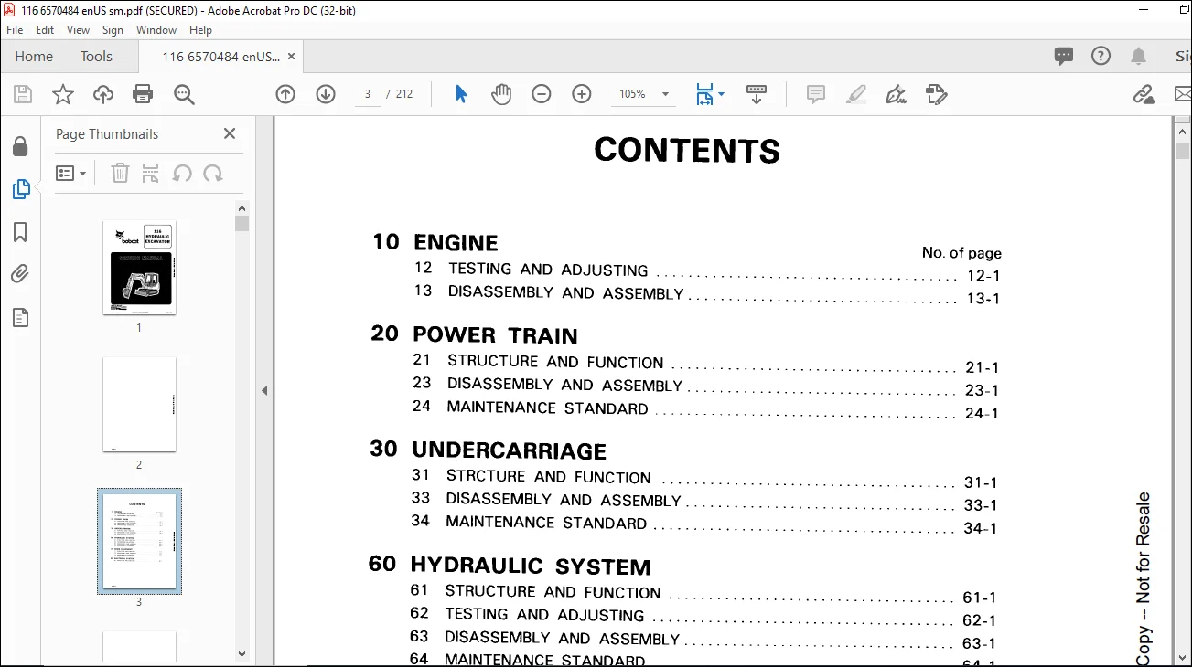
TABLE OF CONTENTS:
Bobcat Hydraulic Excavator 116 Service Manual 6577084 – PDF DOWNLOAD
CONTENTS 3
SAFETY 5
GENERAL PRECAUTIONS 5
PREPARATIONS FOR WORK 5
PRECAUTIONS DURING WORK 6
STANDARD TIGHTENING TORQUE 7
STANDARD TIGHTENING TORQUE FOR BOLTS AND NUTS 7
TIGHTENING TORQUE OF SPLIT FLANGE BOLTS 7
TIGHTENING TORQUE FOR NUTS OF FLARED 8
COATING MATERIALS 8
ELECTRICAL WIRE CODE 9
CLASSIFICATION BY THICKNESS 9
CLASSIFICATION BY COLOR AND CODE 9
WEIGHT TABLE 10
TABLE OF OIL AND COOLANT QUANTITIES 12
ENGINE TESTING AND ADJUSTING 13
TESTING AND ADJUSTING DATA 14
TESTING AND ADJUSTING TOOL LIST 14
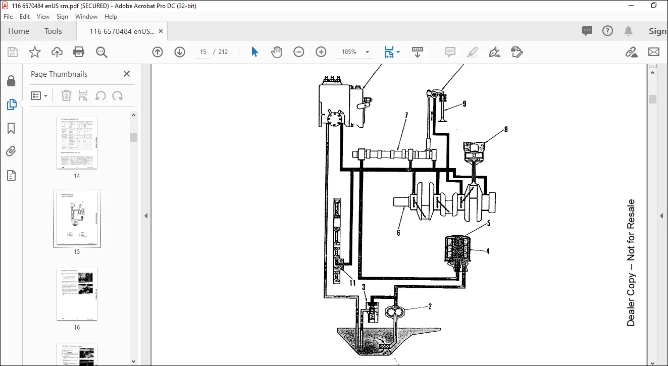
LUBRICATION SYSTEM 15
LUBRICATION SYSTEM CHART 15
ADJUSTING VALVE CLEARANCE 16
MEASURING COMPRESSION PRESSURE 17
ADJUSTING FUEL INJECTION TIMING 18
TESTING AND ADJUSTING FAN BELT TENSION 19
BLEEDING AIR FROM FUEL LINE 19
ENGINE DISASSEMBLY AND ASSEMBLY 21
REMOVAL OF STARTING MOTOR ASSEMBLY 22
INSTALLATION OF STARTING MOTOR ASSEMBLY 22
REMOVAL OF ALTERNATOR ASSEMBLY 22
INSTALLATION OF ALTERNATOR ASSEMBLY 22
REMOVAL OF FAN PULLEY ASSEMBLY 22
INSTALLATION OF FAN PULLEY ASSEMBLY 22
REMOVAL OF WATER PUMP ASSEMBLY 22
INSTALLATION OF WATER PUMP ASSEMBLY 22
REMOVAL OF THERMOSTAT ASSEMBLY 24
INSTALLATION OF THERMOSTAT ASSEMBLY 24
REMOVAL OF NOZZLE HOLDER ASSEMBLY 24
INSTALLATION OF NOZZLE HOLDER ASSEMBLY 24
REMOVAL OF FUEL INJECTION PUMP ASSEMBLY 26
INSTALLATION OF FUEL INJECTION PUMP ASSEMBLY 26
REMOVAL OF CYLINDER HEAD ASSEMBLY 28
REMOVAL OF RADIATOR ASSEMBLY 32
INSTALLATION OF RADIATOR ASSEMBLY 32
REMOVAL OF ENGINE ASSEMBLY 34
INSTALLATION OF ENGINE ASSEMBLY 38
POWER TRAIN STRUCTURE AND FUNCTION 43
POWER TRAIN (S/N 11999 & Below) 44
POWER TRAIN (S/N 12001 & Above) 45
SWING CIRCLE (S/N 11999 & Below) 46
SWING CIRCLE (S/N 12001 & Above) 47
SWING MACHINERY (S/N 11999 & Below) 48
SWING MACHINERY (S/N 12001 & Above) 49
SPROCKET (S/N 11999 & Below) 50
SPROCKET (S/N 12001 & Below) 51
TRACK FRAME AND RECOIL SPRING (S/N 12001 & Above) 52
IDLER (S/N 12001 & Above) 53
TRACK ROLLER 53
TRACK SHOE (S/N 12001 & Above) 54
POWER TRAIN DISASSEMBLY AND ASSEMBLY 55
REMOVAL OF SWING CIRCLE ASSEMBLY 56
INSTALLATION OF SWING CIRCLE ASSEMBLY 58
REMOVAL OF SWING MACHINERY ASSEMBLY 60
INSTALLATION OF SWING MACHINERY ASSEMBLY 60
DISASSEMBLY OF SWING MACHINERY ASSEMBLY 62
ASSEMBLY OF SWING MACHINERY ASSEMBLY 64
POWER TRAIN MAINTENANCE STANDARD 67
SWING CIRCLE (S/N 11999 & Below) 68
SWING CIRCLE (S/N 12001 & Above) 69
SWING MACHINERY (S/N 11999 & Below) 70
SWING MACHINERY (S/N 12001 & Above) 71
SPROCKET (S/N 11999 & Below) 72
SPROCKET (S/N 12001 & Above) 73
UNDERCARRIAGE STRUCTURE AND FUNCTION 75
TRACK FRAME AND RECOIL SPRING 76
IDLER 77
TRACK ROLLER 77
TRACK SHOE 78
UNDERCARRIAGE DISASSEMBLY AND ASSEMBLY 79
REMOVAL OF RECOIL SPRING ASSEMBLY 80
INSTALLATION OF RECOIL SPRING ASSEMBLY 80
DISASSEMBLY OF RECOIL SPRING ASSEMBLY 80
ASSEMBLY OF RECOIL SPRING ASSEMBLY 80
REMOVAL OF TRACK SHOE ASSEMBLY 84
INSTALLATION OF TRACK SHOE ASSEMBLY 84
UNDERCARRIAGE MAINTENANCE STANDARD 87
TRACK FRAME AND RECOIL SPRING (S/N 11999 & Below) 88
TRACK FRAME AND RECOIL SPRING (S/N 12001 & Above) 89
TRACK ROLLER (S/N 11999 & Below) 90
TRACK ROLLER (S/N 12001 & Above) 91
TRACK SHOE (S/N 11999 & Below) 92
TRACK SHOE (S/N 12001 & Above) 93
IDLER (S/N 11999 & Below) 94
IDLER (S/N 12001 & Above) 95
HYDRAULIC CONTROL STRUCTURE AND FUNCTION 97
HYDRAULIC PIPING 98
HYDRAULIC CIRCUIT SCHEMATICS 100
HYDRAULIC CIRCUIT DIAGRAM 101
HYDRAULIC CIRCUIT SCHEMATICS (S/N 12001 & Above) 102
HYDRAULIC CIRCUIT DIAGRAM (S/N 11999 & Below) 103
HYDRAULIC CIRCUIT DIAGRAM (S/N 12001 & Above) 104
HYDRAULIC TANK (S/N 11999 & Below) 105
HYDRAULIC TANK (S/N 12001 & Above) 106
6-SPOOL CONTROL VALVE (S/N 11999 & Below) 107
6-SPOOL CONTROL VALVE (S/N 12001 & Above) 109
4-SPOOL CONTROL VALVE (S/N 12001 & Above) 111
3-SPOOL CONTROL VALVE (S/N 11999 & Below) 112
HYDRAULIC TRIPLE GEAR PUMP (S/N 11999 & Below) 113
CENTER SWIVEL JOINT (S/N 11999 & Above) 114
CENTER SWIVEL JOINT (S/N 12001 & Above) 115
SWING MOTOR (S/N 11999 & Below) 116
SWING MOTOR (S/N 12001 & Above) 117
TRAVEL MOTOR (with reduction gear) (S/N 11999 & Below) 119
BRAKE VALVE 122
VALVE CONTROL (S/N 11999 & Below) 123
VALVE CONTROL (S/N 12001 & Above) 124
HYDRAULIC SYSTEM TESTING AND ADJUSTING 125
TABLE OF JUDGEMENT STANDARD VALUE 126
TESTING AND ADJUSTING TOOL 133
TESTING OPERATING FORCE OF CONTROL LEVER 134
TESTING TRAVEL OF CONTROL LEVER 134
TESTING TRAVEL OF CONTROL VALVE SPOOL 135
TESTING AND ADJUSTING HYDRAULIC PRESSURE 136
MEASURING DELIVERY OF PUMP 138
116 HYDRAULIC PUMP CHECK 140
Checking the Output of the Hydraulic Pump at the Boom Cylinder 140
Adjusting the Main Relief Valve 140
Checking the Output of the Hydraulic Pump at the Arm Cylinder 141
Adjusting the Main Relief Valve 141
Checking the Output of the Hydraulic Pump at the Blade Cylinder 142
Adjusting the Main Relief Valve 142
116 PORT RELIEF VALVE CHECK 143
MEASURING OIL LEAKAGE FROM SWING AND TRAVEL MOTOR 144
MEASURING OIL LEAKAGE FROM CYLINDER 145
HYDRAULIC SYSTEM DISASSEMBLY AND ASSEMBLY 147
REMOVAL OF HYDRAULIC PUMP ASSEMBLY 148
INSTALLATION OF HYDRAULIC PUMP ASSEMBLY 148
REMOVAL OF 6-SPOOL CONTROL VALVE ASSEMBLY 150
INSTALLATION OF 6-SPOOL CONTROL VALVE ASSEMBLY 150
REMOVAL OF 3-SPOOL CONTROL VALVE ASSEMBLY 150
INSTALLATION OF 3-SPOOL CONTROL VALVE ASSEMBLY 150
DISASSEMBLY OF CONTROL VALVE ASSEMBLY 152
ASSEMBLY OF CONTROL VALVE ASSEMBLY 152
REMOVAL OF MAIN RELIEF VALVE ASSEMBLY 154
INSTALLATION OF MAIN RELIEF VALVE ASSEMBLY 154
REMOVAL OF CENTER SWIVEL JOINT ASSEMBLY 156
INSTALLATION OF CENTER SWIVEL JOINT ASSEMBLY 156
DISASSEMBLY OF CENTER SWIVEL JOINT ASSEMBLY 158
ASSEMBLY OF CENTER SWIVEL JOINT ASSEMBLY 158
REMOVAL OF SWING MOTOR ASSEMBLY 160
INSTALLATION OF SWING MOTOR ASSEMBLY 160
REMOVAL OF TRAVEL MOTOR ASSEMBLY 160
INSTALLATION OF TRAVEL MOTOR ASSEMBLY 160
REMOVAL OF BOOM CYLINDER ASSEMBLY 162
INSTALLATION OF BOOM CYLINDER ASSEMBLY 162
REMOVAL OF ARM CYLINDER ASSEMBLY 162
INSTALLATION OF ARM CYLINDER ASSEMBLY 162
REMOVAL OF BUCKET CYLINDER ASSEMBLY 164
INSTALLATION OF BUCKET CYLINDER ASSEMBLY 164
REMOVAL OF BLADE CYLINDER ASSEMBLY 164
INSTALLATION OF BLADE CYLINDER ASSEMBLY 164
REMOVAL OF BOOM SWING CYLINDER ASSEMBLY 166
INSTALLATION OF BOOM SWING CYLINDER ASSEMBLY 166
DISASSEMBLY OF HYDRAULIC CYLINDER ASSEMBLY 168
ASSEMBLY OF HYDRAULIC CYLINDER ASSEMBLY 170
HYDRAULIC SYSTEM MAINTENANCE STANDARD 175
SWING MOTOR (S/N 12001 & Above) 176
6-SPOOL CONTROL VALVE (S/N 11999 & Below) 177
6-SPOOL CONTROL VALVE (S/N 12001 & Above) 178
4-SPOOL CONTROL VALVE (S/N 12001 & Above) 179
3-SPOOL CONTROL VALVE (S/N 11999 & Below) 180
HYDRAULIC CYLINDER (S/N 11999 & Below) 181
HYDRAULIC CYLINDER (S/N 12001 & Above) 183
TRIPLE GEAR PUMP (S/N 11999 & Below) 185
TRIPLE GEAR PUMP (S/N 12001 & Above) 186
WORK EQUIPMENT STRUCTURE AND FUNCTION 187
WORK EQUIPMENT 188
WORK EQUIPMENT (S/N 12001 & Above) 189
WORK EQUPMENT DISASSEMBLY AND ASSEMBLY 191
REMOVAL OF WORK EQUIPMENT ASSEMBLY 192
INSTALLATION OF WORK EQUIPMENT ASSEMBLY 192
REMOVAL OF BLADE ASSEMBLY 192
INSTALLATION OF BLADE ASSEMBLY 192
REMOVAL OF ARM AND BUCKET ASSEMBLY 194
INSTALLATION OF ARM AND BUCKET ASSEMBLY 194
REMOVAL OF BUCKET ASSEMBLY 194
INSTALLATION OF BUCKET ASSEMBLY 194
REMOVAL OF ARM ASSEMBLY 196
INSTALLATION OF ARM ASSEMBLY 196
REMOVAL OF BOOM ASSEMBLY 196
INSTALLATION OF BOOM ASSEMBLY 196
REMOVAL OF FLOOR FRAME ASSEMBLY 198
INSTALLATION OF FLOOR FRAME ASSEMBLY 198
WORK EQUIPMENT MAINTENANCE STANDARD 201
WORK EQUIPMENT 202
ELECTRICAL SYSTEM STRUCTURE AND FUNCTION 205
ELECTRICAL CIRCUIT DIAGRAM 207
ELECTRICAL CIRCUIT DIAGRAM (S/N 12001 & Above) 208
SERVICE MANUAL REVISION 209
116-1 209
116-2 211
IMAGES PREVIEW OF THE MANUAL:
Need help? Contact: [email protected]
PLEASE NOTE:
- This is the SAME MANUAL used by the dealerships to diagnose your vehicle
- No waiting for couriers / posts as this is a PDF manual and you can download it within 2 minutes time once you make the payment.
- Your payment is all safe and the delivery of the manual is INSTANT – You will be taken to the DOWNLOAD PAGE.
- So have no hesitations whatsoever and write to us about any queries you may have : heydownloadss @gmail.com
S.M