BOBCAT INGERSOLL RAND BL-370 BL-375 Service Manual PDF DOWNLOAD
$30.95
BOBCAT INGERSOLL RAND BL-370 BL-375 Service Manual PDF DOWNLOAD
S/N 570411001 & Above
S/N 571811001 & Above
Description
BOBCAT INGERSOLL RAND BL-370 BL-375 Service Manual PDF DOWNLOAD
FILE DETAILS:
BOBCAT INGERSOLL RAND BL-370 BL-375 Service Manual PDF DOWNLOAD
Language : English
Pages : 654
Downloadable : Yes
File Type : PDF
IMAGES PREVIEW OF THE MANUAL:
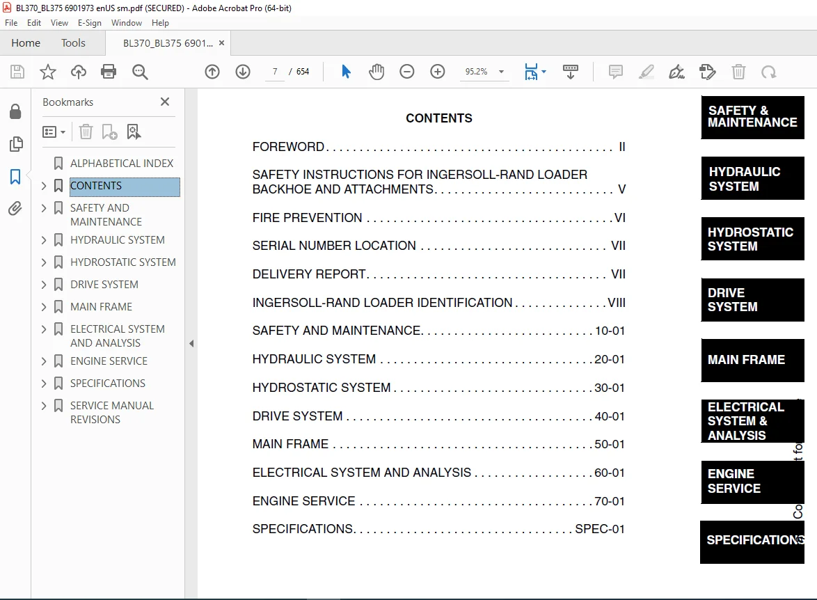
TABLE OF CONTENTS:
BOBCAT INGERSOLL RAND BL-370 BL-375 Service Manual PDF DOWNLOAD
S/N 570411001 & Above
S/N 571811001 & Above
ALPHABETICAL INDEX………………………………………………….. 5
CONTENTS…………………………………………………………… 7
FOREWORD……………………………………………………….. 8
SAFETY INSTRUCTIONS FOR INGERSOLL-RAND LOADER BACKHOE AND ATTACHMENTS…. 11
SAFE OPERATION IS THE OPERATOR’S RESPONSIBILITY…………………….. 11
FIRE PREVENTION…………………………………………………. 12
SERIAL NUMBER LOCATION…………………………………………… 13
Loader Backhoe Serial Number………………………………….. 13
Engine Serial Number…………………………………………. 13
DELIVERY REPORT…………………………………………………. 13
INGERSOLL-RAND LOADER IDENTIFICATION………………………………. 14
SAFETY AND MAINTENANCE………………………………………………. 15
LIFTING AND BLOCKING THE LOADER BACKHOE……………………………. 17
Procedure…………………………………………………… 17
LIFT ARM SUPPORT DEVICE………………………………………….. 19
Installing The Lift Arm Support Device…………………………. 19
Removing The Lift Arm Support Device…………………………… 20
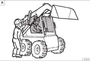
ENGINE COVER……………………………………………………. 21
TRANSPORTING THE LOADER BACKHOE…………………………………… 23
Procedure…………………………………………………… 23
TOWING THE LOADER BACKHOE………………………………………… 25
Procedure…………………………………………………… 25
AXLE TOE-IN…………………………………………………….. 27
Adjustment………………………………………………….. 27
SERVICE SCHEDULE………………………………………………… 29
Chart………………………………………………………. 29
AIR CLEANER SERVICE……………………………………………… 31
Replacing Filter Element……………………………………… 31
ENGINE COOLING SYSTEM……………………………………………. 33
Coolant Replacement………………………………………….. 33
FUEL SYSTEM…………………………………………………….. 35
Fuel Specifications………………………………………….. 35
Filling The Fuel Tank………………………………………… 35
Fuel Filter…………………………………………………. 36
ENGINE LUBRICATION SYSTEM………………………………………… 37
Checking Engine Oil………………………………………….. 37
Oil Chart…………………………………………………… 37
Replacing Oil And Filter……………………………………… 38
HYDRAULIC/HYDROSTATIC SYSTEM……………………………………… 41
Checking And Adding Fluid…………………………………….. 41
Cleaning The Cooler………………………………………….. 41
Replacing Hydraulic/Hydrostatic Filter…………………………. 42
Replacing Hydraulic Fluid…………………………………….. 43
REAR AXLE………………………………………………………. 45
Checking Oil Level…………………………………………… 45
Draining Oil………………………………………………… 45
FRONT AXLE……………………………………………………… 46
Checking Oil Level…………………………………………… 46
Draining Oil………………………………………………… 46
BACKHOE BOOM LOCK……………………………………………….. 47
Disengaging The Boom Lock…………………………………….. 47
Engaging Boom Lock…………………………………………… 48
BOB-TACH HAND LEVER……………………………………………… 49
Inspection And Maintenance……………………………………. 49
ALTERNATOR BELT…………………………………………………. 51
Adjusting The Alternator Belt…………………………………. 51
LUBRICATING THE LOADER BACKHOE……………………………………. 53
TIRE MAINTENANCE………………………………………………… 61
Wheel Nuts………………………………………………….. 61
Mounting……………………………………………………. 61
Tire Pressure……………………………………………….. 61
HYDRAULIC SYSTEM……………………………………………………. 63
HYDRAULIC/HYDROSTATIC SCHEMATICS………………………………….. 67
HYDRAULIC SYSTEM INFORMATION……………………………………… 72
Troubleshooting……………………………………………… 76
Description…………………………………………………. 77
ARM CYLINDER……………………………………………………. 78
Checking……………………………………………………. 78
Removal And Installation……………………………………… 80
Parts Identification…………………………………………. 82
Disassembly…………………………………………………. 83
Assembly……………………………………………………. 86
BOOM CYLINDER…………………………………………………… 90
Checking……………………………………………………. 90
Removal And Installation……………………………………… 91
Parts Identification…………………………………………. 93
Disassembly…………………………………………………. 94
Assembly……………………………………………………. 97
SWING CYLINDER (WITHOUT SIDESHIFT)…………………………………100
Removal And Installation………………………………………100
Bushing Removal And Installation……………………………….101
Parts Identification (Left Side)……………………………….102
Parts Identification (Right Side)………………………………103
Disassembly………………………………………………….104
Assembly…………………………………………………….107
SWING CYLINDER (WITH SIDESHIFT)……………………………………110
Not Available At Time Of Printing………………………………110
BUCKET CYLINDER………………………………………………….112
Checking…………………………………………………….112
Removal And Installation………………………………………114
Parts Identification………………………………………….116
Disassembly………………………………………………….117
Assembly…………………………………………………….120
STABILIZER CYLINDER (WITHOUT SIDESHIFT)…………………………….124
Checking…………………………………………………….124
Removal And Installation………………………………………126
Parts Identification………………………………………….129
Disassembly………………………………………………….130
Assembly…………………………………………………….133
STABILIZER CYLINDER (WITH SIDESHIFT)……………………………….136
Not Available At Time Of Printing………………………………136
TILT CYLINDER……………………………………………………138
Checking…………………………………………………….138
Removal And Installation………………………………………139
Parts Identification (Left Side)……………………………….140
Parts Identification (Right Side)………………………………141
Disassembly………………………………………………….142
Assembly…………………………………………………….145
LIFT CYLINDER……………………………………………………148
Checking…………………………………………………….148
Removal And Installation………………………………………149
Parts Identification (Left Side)……………………………….151
Parts Identification (Right Side)………………………………152
Disassembly………………………………………………….153
Assembly…………………………………………………….156
STEERING CYLINDER (FRONT)…………………………………………160
Removal And Installation………………………………………160
Parts Identification………………………………………….164
Disassembly And Assembly………………………………………165
Inspection…………………………………………………..168
STEERING CYLINDER (REAR)………………………………………….170
Removal And Installation………………………………………170
Parts Identification………………………………………….173
Disassembly And Assembly………………………………………174
Inspection…………………………………………………..177
MAIN RELIEF VALVE………………………………………………..178
Testing The Main Relief Valve………………………………….178
Adjustment…………………………………………………..179
PORT RELIEF VALVE (BACKHOE CONTROL VALVE)…………………………..180
Testing And Adjusting (Arm Control)…………………………….180
Testing And Adjusting (Boom Control)……………………………182
Testing And Adjusting (Boom Swing Control)………………………184
LOADER CONTROL VALVE……………………………………………..186
Removal And Installation………………………………………186
Parts Identification………………………………………….188
Disassembly And Assembly………………………………………189
Inlet/Outlet Valve Section…………………………………….189
Lift Arm Valve Section………………………………………..191
Tilt Valve Section……………………………………………195
Auxiliary Valve Section (Front)………………………………..200
Auxiliary Valve Section (Rear)…………………………………205
BACKHOE CONTROL VALVE…………………………………………….210
Removal And Installation………………………………………210
Parts Identification………………………………………….212
Disassembly And Assembly………………………………………213
Inlet/Outlet Valve Section…………………………………….215
Arm Valve Section…………………………………………….217
Tilt Valve Section……………………………………………220
Right Stabilizer Valve Section…………………………………223
Left Stabilizer Valve Section………………………………….226
Boom Valve Section……………………………………………230
Boom Swing Valve Section………………………………………233
Outlet Valve Section………………………………………….236
HYDRAULIC FLUID RESERVOIR…………………………………………238
Removal And Installation………………………………………238
Filter Removal And Installation………………………………..240
HYDRAULIC FILTER HOUSING………………………………………….242
Removal And Installation………………………………………242
Disassembly………………………………………………….243
Assembly…………………………………………………….244
GEAR PUMP……………………………………………………….246
Removal And Installation………………………………………246
Parts Identification………………………………………….247
Disassembly And Assembly………………………………………248
Inspection…………………………………………………..250
STEERING PUMP……………………………………………………252
Removal And Installation………………………………………252
Parts Identification………………………………………….254
Disassembly………………………………………………….255
Inspection…………………………………………………..264
Assembly…………………………………………………….264
MASTER CYLINDER………………………………………………….274
Removal And Installation………………………………………274
Parts Identification………………………………………….275
Disassembly And Assembly………………………………………276
STEERING VALVE…………………………………………………..278
Removal And Installation………………………………………278
Adjustment…………………………………………………..279
HYDROSTATIC SYSTEM…………………………………………………..280
HYDROSTATIC SYSTEM INFORMATION…………………………………….282
Troubleshooting Chart…………………………………………282
Replenishing Valve Function……………………………………283
OIL COOLER………………………………………………………284
Disassembly………………………………………………….284
Inspection…………………………………………………..285
Assembly…………………………………………………….285
HYDROSTATIC DRIVE MOTOR…………………………………………..288
Removal And Installation………………………………………288
Parts Identification………………………………………….290
Disassembly………………………………………………….291
Inspection…………………………………………………..304
Assembly…………………………………………………….307
HYDROSTATIC PUMP…………………………………………………320
Removal And Installation………………………………………320
Parts Identification………………………………………….323
Disassembly………………………………………………….324
Inspection…………………………………………………..344
Assembly…………………………………………………….346
HYDROSTATIC TESTING………………………………………………366
Pump Adjustment………………………………………………366
Operation Test – Creep Test:…………………………………..368
Operation Test – Torque Limiter Test:…………………………..368
DRIVE SYSTEM………………………………………………………..370
TROUBLESHOOTING………………………………………………….372
Chart……………………………………………………….372
PARKING BRAKE……………………………………………………374
Lever Removal And Installation…………………………………374
Cable Removal And Installation…………………………………376
Adjustment…………………………………………………..377
PARKING BRAKE HOUSING…………………………………………….378
Removal And Installation………………………………………378
Parts Identification………………………………………….379
Disassembly And Assembly………………………………………380
SERVICE BRAKE……………………………………………………390
Description………………………………………………….390
Bleeding The Brake Circuit…………………………………….390
REAR AXLE……………………………………………………….392
Removal……………………………………………………..392
Installation…………………………………………………395
FRONT AXLE………………………………………………………400
Removal……………………………………………………..400
Installation…………………………………………………402
Installation…………………………………………………402
Axle Pivot Bushing Removal And Installation……………………..404
DRIVESHAFT………………………………………………………406
Removal And Installation………………………………………406
DROP BOX………………………………………………………..408
Removal And Installation………………………………………408
Parts Identification………………………………………….411
Disassembly………………………………………………….413
Inspection…………………………………………………..418
Assembly…………………………………………………….420
BRAKE PEDAL ASSEMBLY……………………………………………..428
Removal And Installation………………………………………428
MAIN FRAME………………………………………………………….432
OPERATOR CANOPY………………………………………………….434
Removal And Installation………………………………………434
ENCLOSED CAB…………………………………………………….440
Not Available At Time Of Printing………………………………440
OPERATOR SEAT……………………………………………………442
Removal And Installation………………………………………442
FLOOR PANELS…………………………………………………….444
Front Panel Removal And Installation……………………………444
Rear Panel Removal And Installation…………………………….444
Front Right Panel Removal And Installation………………………445
Front Left Panel Removal And Installation……………………….445
GRILL…………………………………………………………..446
Removal And Installation………………………………………446
GRILL FRAME……………………………………………………..448
Removal And Installation………………………………………448
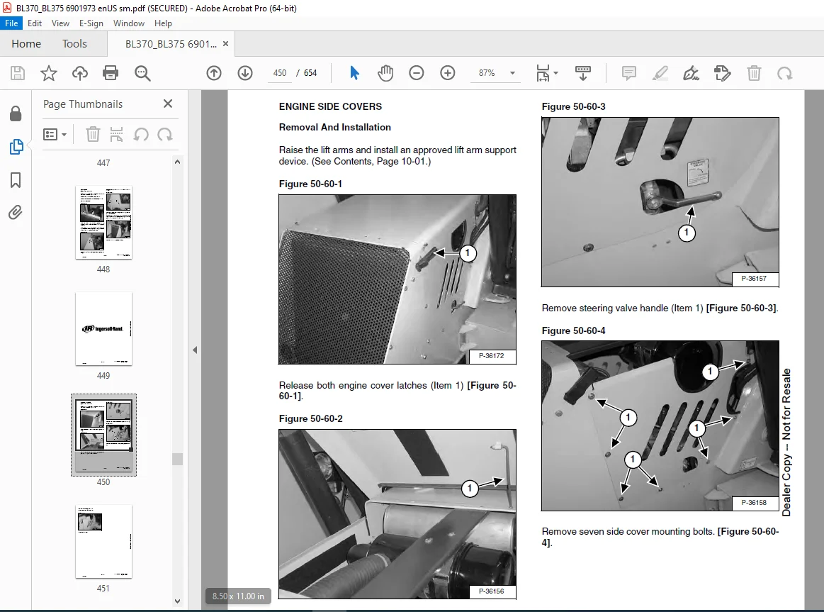
ENGINE SIDE COVERS……………………………………………….450
Removal And Installation………………………………………450
FENDER………………………………………………………….452
Removal And Installation………………………………………452
ENGINE COVER…………………………………………………….454
Removal And Installation………………………………………454
FUEL TANK……………………………………………………….456
Removal And Installation………………………………………456
Screen Removal And Installation………………………………..458
LIFT ARMS……………………………………………………….460
Removal And Installation………………………………………460
BOB-TACH………………………………………………………..464
Removal And Installation………………………………………464
Bob-Tach Lever And Wedge………………………………………466
Pivot Pin Bushing Removal And Installation………………………467
ARM…………………………………………………………….468
Removal And Installation………………………………………468
Arm Pivot Bushing Removal And Installation………………………470
BOOM (WITHOUT SIDESHIFT)………………………………………….472
Removal And Installation………………………………………472
BOOM (WITH SIDESHIFT)…………………………………………….476
Not Available At Time Of Printing………………………………476
SWING FRAME (WITHOUT SIDESHIFT)……………………………………478
Removal And Installation………………………………………478
Bushing Removal And Installation……………………………….479
SWING FRAME (WITH SIDESHIFT)………………………………………480
Not Available At Time Of Printing………………………………480
X-CHANGE™……………………………………………………….482
Removal And Installation………………………………………482
BUCKET………………………………………………………….484
Backhoe Bucket Teeth Removal And Installation……………………484
Loader Bucket Teeth Removal And Installation…………………….484
LIFT ARM STABILIZER………………………………………………486
Removal And Installation………………………………………486
CENTER FLOOR PANEL……………………………………………….488
Removal And Installation………………………………………488
STABILIZER (WITHOUT SIDESHIFT)…………………………………….492
Removal And Installation………………………………………492
STABILIZER (WITH SIDESHIFT)……………………………………….494
Not Available At Time Of Printing………………………………494
FRONT AXLE PIVOT FRAME……………………………………………496
Not Available At Time Of Printing………………………………496
ELECTRICAL SYSTEM AND ANALYSIS………………………………………..498
ELECTRICAL SCHEMATIC……………………………………………..500
ELECTRICAL SYSTEM INFORMATION……………………………………..505
Troubleshooting Chart…………………………………………505
Description………………………………………………….506
Fuse Location………………………………………………..506
Relay Location……………………………………………….506
BATTERY…………………………………………………………507
Removal And Installation………………………………………507
Servicing The Electrical System………………………………..508
Using A Booster Battery (Jump Starting)…………………………509
ALTERNATOR………………………………………………………511
Adjusting The Alternator Belt………………………………….511
Description………………………………………………….511
Tests……………………………………………………….512
Alternator Output Test………………………………………..512
Full Field Test………………………………………………513
Alternator Regulator Test……………………………………..513
Alternator Regulator Test With Voltmeter………………………..514
Removal And Installation………………………………………515
Parts Identification………………………………………….516
Pulley Removal And Installation………………………………..517
Disassembly And Assembly………………………………………518
Rotor Continuity Test…………………………………………521
Stator Continuity Test………………………………………..521
Rectifier Continuity (Diode) Test………………………………522
Brush Length…………………………………………………522
STARTER…………………………………………………………523
Removal And Installation………………………………………523
Checking The Starter In The Loader……………………………..523
Parts Identification………………………………………….525
Disassembly………………………………………………….526
Inspection And Repair…………………………………………531
No Load Test…………………………………………………535
Assembly…………………………………………………….536
FRONT LIGHTS…………………………………………………….543
Bulb Removal And Installation………………………………….543
Housing Removal And Installation……………………………….545
TURN INDICATOR LIGHTS (FRONT)……………………………………..547
Bulb Removal And Installation………………………………….547
TURN INDICATOR LIGHTS (REAR)………………………………………549
Bulb Removal And Installation………………………………….549
CAB LIGHTS………………………………………………………551
Bulb Removal And Installation………………………………….551
Housing Removal And Installation……………………………….553
FUEL LEVEL SENDER………………………………………………..555
Removal And Installation………………………………………555
INSTRUMENT PANEL…………………………………………………557
Removal And Installation………………………………………557
ENGINE SERVICE………………………………………………………559
TROUBLESHOOTING………………………………………………….561
Chart……………………………………………………….561
ENGINE SPEED CONTROL……………………………………………..563
Removal And Installation………………………………………563
Cable Removal And Installation…………………………………564
TRAVEL PEDAL…………………………………………………….567
Removal And Installation………………………………………567
MUFFLER…………………………………………………………569
Removal And Installation………………………………………569
AIR CLEANER……………………………………………………..571
Removal And Installation………………………………………571
RADIATOR………………………………………………………..573
Removal And Installation………………………………………573
ENGINE COMPONENTS AND TESTING……………………………………..575
Valve Clearance Adjustment…………………………………….575
Engine Compression Checking……………………………………576
Fuel Shut-Off Solenoid Removal And Installation………………….577
Checking Fuel Injection Pump…………………………………..578
Fuel Injection Pump Removal And Installation…………………….579
Fuel Injection Pump Timing…………………………………….581
Fuel Injector Nozzles…………………………………………582
Fuel Injector Nozzles Removal And Installation…………………..583
Fuel Injector Nozzles Check……………………………………584
ENGINE………………………………………………………….585
Removal And Installation………………………………………585
Mount Replacement…………………………………………….589
RECONDITIONING THE ENGINE…………………………………………591
Cylinder Head Removal And Installation………………………….591
Cylinder Head Disassembly And Assembly………………………….592
Cylinder Head Servicing……………………………………….593
Cylinder Head Top Clearance……………………………………593
Valve Guide Checking………………………………………….594
Reconditioning The Valve And Valve Seat…………………………595
Valve Spring…………………………………………………596
Rocker Arm And Shaft Checking………………………………….596
Timing Gearcase Cover Removal And Installation…………………..597
Idler Gear And Camshaft Removal And Installation…………………599
Camshaft Servicing……………………………………………600
Idler Gear And Shaft Servicing…………………………………601
Timing Gears Checking Backlash…………………………………602
Fuel Camshaft Removal And Installation………………………….603
Fuel Camshaft Governor………………………………………..603
Crankshaft Gear Removal And Installation………………………..604
Oil Pump Removal And Installation………………………………604
Oil Pump Service……………………………………………..604
Checking Engine Oil Pressure…………………………………..605
Oil Pump Relief Valve…………………………………………606
Piston And Connecting Rod Removal And Installation……………….606
Piston And Connecting Rod Servicing…………………………….608
Connecting Rod Alignment………………………………………610
Crankshaft And Bearings Removal And Installation…………………610
Crankshaft And Bearings, Servicing……………………………..612
Cylinder Bore, Checking……………………………………….615
Water Pump Removal And Installation…………………………….616
Water Pump Disassembly And Assembly…………………………….616
FLYWHEEL HOUSING…………………………………………………617
Removal And Installation………………………………………617
FLYWHEEL………………………………………………………..619
Removal And Installation………………………………………619
Ring Gear Removal And Installation……………………………..619
DRIVE COUPLER……………………………………………………621
Removal And Installation………………………………………621
TURBOCHARGER…………………………………………………….623
Not Available At Time Of Printing………………………………623
SPECIFICATIONS………………………………………………………625
LOADER SPECIFICATIONS…………………………………………….627
Loader Backhoe Dimensions……………………………………..627
Performance………………………………………………….628
Controls…………………………………………………….628
Engine………………………………………………………628
Hydraulic System……………………………………………..629
Electrical…………………………………………………..629
Drive System…………………………………………………630
Capacities…………………………………………………..630
Tires……………………………………………………….630
ENGINE SPECIFICATIONS…………………………………………….631
Fuel Injection Nozzles………………………………………..631
Fuel Injection Pump…………………………………………..631
Cylinder Head………………………………………………..631
Valves………………………………………………………631
Valve Springs………………………………………………..632
Valve Timing…………………………………………………632
Rocker Arms………………………………………………….632
Camshaft…………………………………………………….632
Cylinders……………………………………………………632
Tappet………………………………………………………632
Piston Rings…………………………………………………633
Pistons……………………………………………………..633
Crankshaft…………………………………………………..633
Oil Pump…………………………………………………….633
Thermostat…………………………………………………..634
Connecting Rods………………………………………………634
Timing Gear………………………………………………….634
Engine Bolt Torque……………………………………………635
Grinding Specifications for the Crankshaft………………………636
LOADER BACKHOE TORQUE…………………………………………….637
Specifications……………………………………………….637
TORQUE SPECIFICATIONS FOR BOLTS……………………………………639
Torque For General Metric Bolts………………………………..639
HYDRAULIC/HYDROSTATIC FLUID SPECIFICATIONS………………………….641
Specifications……………………………………………….641
CONVERSIONS……………………………………………………..643
Decimal And Millimeter Equivalents……………………………..643
U.S. To Metric Conversion……………………………………..643
PARTS MANAGER………………………………………………..645
SERVICE MANAGER X…………………………………………….645
SALES MANAGER………………………………………………..645
Revision No: BL-370/BL-375-1…………………………………..645
Date: 22 January 2002…………………………………………645
Product: Bobcat Loader Backhoe…………………………………645
Model: BL-370/BL-375………………………………………….645
Manual No: 6901973 (12-02)…………………………………….645
PARTS MANAGER………………………………………………..647
SERVICE MANAGER X…………………………………………….647
SALES MANAGER………………………………………………..647
Revision No: BL-370/BL-375-3…………………………………..647
Date: 1 June 2003…………………………………………….647
Product: Loader Backhoe……………………………………….647
Model: BL-370/BL-375………………………………………….647
Manual No: 6901973 (12-02)…………………………………….647
PARTS MANAGER………………………………………………..649
SERVICE MANAGER X…………………………………………….649
SALES MANAGER………………………………………………..649
Revision No: BL-370/BL-375-3…………………………………..649
Date: 1 June 2003…………………………………………….649
Product: Loader Backhoe……………………………………….649
Model: BL-370/BL-375………………………………………….649
Manual No: 6901973 (12-02)…………………………………….649
PARTS MANAGER………………………………………………..651
SERVICE MANAGER X…………………………………………….651
SALES MANAGER………………………………………………..651
Revision No: BL-370/BL-375-4…………………………………..651
Date: 1 January 2004………………………………………….651
Product: Loader Backhoe……………………………………….651
Model: BL-370/BL-375………………………………………….651
Manual No: 6901973 (12-02)…………………………………….651
SERVICE MANUAL REVISIONS …………………………………………….645
BL-370/BL-375-1 …………………………………………………645
BL-370/BL-375-2………………………………………………….647
BL-370/BL-375-3………………………………………………….649
BL-370/BL-375-4………………………………………………….651
BL-370/BL-375-5………………………………………………….653
Contact us: [email protected]
https://vimeo.com/842136778?share=copy
DESCRIPTION:
BOBCAT INGERSOLL RAND BL-370 BL-375 Service Manual PDF DOWNLOAD
FOREWORD
This manual is for the Ingersoll-Rand loader mechanic. It provides necessary servicing and
adjustment procedures for the Ingersoll-Rand loader and its component parts and systems. Refer to
the Operation & Maintenance Manual for operating instructions, Starting procedure, daily checks, etc.
SAFETY INSTRUCTIONS FOR INGERSOLL-RAND LOADER BACKHOE AND ATTACHMENTS
SAFE OPERATION IS THE OPERATOR’S RESPONSIBILITY
Carefully follow the operating and maintenance instructions in this manual.
- The Ingersoll-Rand loader backhoe is highly maneuverable and compact. It is rugged and useful under a wide variety of conditions. This presents an operator with hazards associated with off-highway, rough terrain applications, common with Ingersoll-Rand loader backhoe usage.
- The Ingersoll-Rand loader backhoe has an internal combustion engine with resultant heat and exhaust. All exhaust gases can kill or cause illness, so use the loader backhoe with adequate ventilation. The loader backhoe has a spark arrestor exhaust system or muffler which is required for operation in certain areas.
- The dealer explains the capabilities and restrictions of the Ingersoll-Rand loader backhoe and attachments for each application. The dealer demonstrates the safe operation according to Ingersoll-Rand instructional materials, which are also available to operators. The dealer can also identify unsafe modifications or use of unapproved attachments. The attachments and buckets are designed for a Rated Operating Capacity (some have restricted lift heights) and secure fastening to the Ingersoll-Rand loader backhoe. The user must check with the dealer, or Ingersoll-Rand literature, to determine safe loads of materials of specified densities for the loader backhoe-attachment combination.
The following publications and training materials provide information on the safe use and maintenance of the Ingersoll-Rand loader backhoe and attachments:
PLEASE NOTE:
- This is the same manual used by the dealers to diagnose and troubleshoot your vehicle
- You will be directed to the download page as soon as the purchase is completed. The whole payment and downloading process will take anywhere between 2-5 minutes
- Need any other service / repair / parts manual, please feel free to contact [email protected] . We still have 50,000 manuals unlisted
G.P