BOBCAT BL-470 BL-475 INGERSOLL RAND Service Manual PDF DOWNLOAD
$30.95
BOBCAT BL-470 BL-475 INGERSOLL RAND Service Manual PDF DOWNLOAD
BL 470 S/N 570511001 & Above
BL 475 S/N 571911001 & Above
Description
BOBCAT BL-470 BL-475 INGERSOLL RAND Service Manual PDF DOWNLOAD
FILE DETAILS:
BOBCAT BL-470 BL-475 INGERSOLL RAND Service Manual PDF DOWNLOAD
Language : English
Pages : 628
Downloadable : Yes
File Type : PDF
IMAGES PREVIEW OF THE MANUAL:
TABLE OF CONTENTS:
BOBCAT BL-470 BL-475 INGERSOLL RAND Service Manual PDF DOWNLOAD
BL 470 S/N 570511001 & Above
BL 475 S/N 571911001 & Above
ALPHABETICAL INDEX………………………………………………….. 5
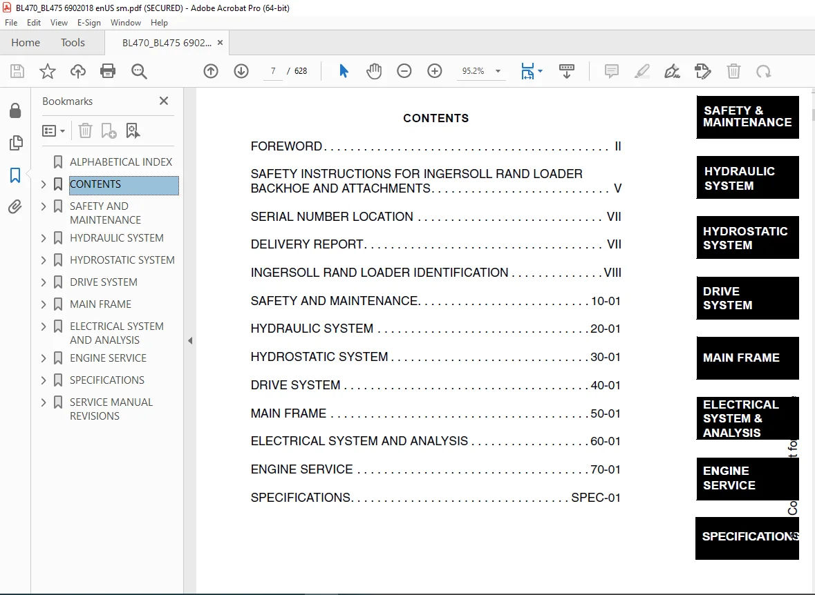
CONTENTS…………………………………………………………… 7
FOREWORD……………………………………………………….. 8
SAFETY INSTRUCTIONS FOR INGERSOLL RAND LOADER BACKHOE AND ATTACHMENTS…. 11
SAFE OPERATION IS THE OPERATOR’S RESPONSIBILITY…………………….. 11
FIRE PREVENTION…………………………………………………. 12
SERIAL NUMBER LOCATION…………………………………………… 13
Loader Backhoe Serial Number………………………………….. 13
Engine Serial Number…………………………………………. 13
DELIVERY REPORT…………………………………………………. 13
INGERSOLL RAND LOADER IDENTIFICATION………………………………. 14
SAFETY AND MAINTENANCE………………………………………………. 15
LIFTING AND BLOCKING THE LOADER BACKHOE……………………………. 17
Procedure…………………………………………………… 17
LIFT ARM SUPPORT DEVICE………………………………………….. 19
Installing The Lift Arm Support Device…………………………. 19
Removing The Lift Arm Support Device…………………………… 20
ENGINE COVER……………………………………………………. 21
TRANSPORTING THE LOADER BACKHOE…………………………………… 23
Procedure…………………………………………………… 23
TOWING THE LOADER BACKHOE………………………………………… 25
Procedure…………………………………………………… 25
AXLE TOE-IN…………………………………………………….. 27
Adjustment………………………………………………….. 27
SERVICE SCHEDULE………………………………………………… 29
Chart………………………………………………………. 29
AIR CLEANER SERVICE……………………………………………… 31
Replacing Filter Element……………………………………… 31
ENGINE COOLING SYSTEM……………………………………………. 33
Coolant Replacement………………………………………….. 33
FUEL SYSTEM…………………………………………………….. 35
Fuel Specifications………………………………………….. 35
Filling The Fuel Tank………………………………………… 35
Fuel Filter…………………………………………………. 36
ENGINE LUBRICATION SYSTEM………………………………………… 37
Checking Engine Oil………………………………………….. 37
Oil Chart…………………………………………………… 37
Replacing Oil And Filter……………………………………… 38
HYDRAULIC/HYDROSTATIC SYSTEM……………………………………… 41
Checking And Adding Fluid…………………………………….. 41
Cleaning The Cooler………………………………………….. 41
Replacing Hydraulic/Hydrostatic Filter…………………………. 42
Replacing Hydraulic Fluid…………………………………….. 43
REAR AXLE………………………………………………………. 45
Checking Oil Level…………………………………………… 45
Draining Oil………………………………………………… 45
FRONT AXLE……………………………………………………… 46
Checking Oil Level…………………………………………… 46
Draining Oil………………………………………………… 46
BACKHOE BOOM LOCK……………………………………………….. 47
Disengaging The Boom Lock…………………………………….. 47
Engaging Boom Lock…………………………………………… 48
BOB-TACH HAND LEVER……………………………………………… 49
Inspection And Maintenance……………………………………. 49
ALTERNATOR BELT…………………………………………………. 51
Adjusting The Alternator Belt…………………………………. 51
LUBRICATING THE LOADER BACKHOE……………………………………. 53
TIRE MAINTENANCE………………………………………………… 61
Wheel Nuts………………………………………………….. 61
Mounting……………………………………………………. 61
Tire Pressure……………………………………………….. 61
HYDRAULIC SYSTEM……………………………………………………. 63
HYDRAULIC/HYDROSATIC SCHEMATICS…………………………………… 67
HYDRAULIC SYSTEM INFORMATION……………………………………… 71
Troubleshooting……………………………………………… 75
Description…………………………………………………. 76
ARM CYLINDER……………………………………………………. 77
Checking……………………………………………………. 77
Removal And Installation……………………………………… 79
Parts Identification…………………………………………. 81
Disassembly…………………………………………………. 82
Assembly……………………………………………………. 85
BOOM CYLINDER…………………………………………………… 89
Checking……………………………………………………. 89
Removal And Installation……………………………………… 90
Parts Identification…………………………………………. 92
Disassembly…………………………………………………. 93
Assembly……………………………………………………. 96
SWING CYLINDER (WITHOUT SIDESHIFT)………………………………… 99
Removal And Installation……………………………………… 99
Bushing Removal And Installation……………………………….100
SWING CYLINDER (WITH SIDESHIFT)……………………………………101
Removal And Installation………………………………………101
Bushing Removal And Installation……………………………….102
BUCKET CYLINDER………………………………………………….103
Checking…………………………………………………….103
Removal And Installation………………………………………105
Parts Identification………………………………………….107
Disassembly………………………………………………….108
Assembly…………………………………………………….111
STABILIZER CYLINDER (WITHOUT SIDESHIFT)…………………………….115
Checking…………………………………………………….115
Removal And Installation………………………………………117
Parts Identification………………………………………….120
Disassembly………………………………………………….121
Assembly…………………………………………………….124
STABILIZER CYLINDER (WITH SIDESHIFT)……………………………….127
Checking…………………………………………………….127
Removal And Installation………………………………………129
TILT CYLINDER……………………………………………………133
Checking…………………………………………………….133
Removal And Installation………………………………………134
Parts Identification (Left Side)……………………………….135
Parts Identification (Right Side)………………………………136
Disassembly………………………………………………….137
Assembly…………………………………………………….140
LIFT CYLINDER……………………………………………………143
Checking…………………………………………………….143
Removal And Installation………………………………………144
Parts Identification (Left Side)……………………………….146
Parts Identification (Right Side)………………………………147
Disassembly………………………………………………….148
Assembly…………………………………………………….151
STEERING CYLINDER (FRONT)…………………………………………155
Removal And Installation………………………………………155
STEERING CYLINDER (FRONT) (CONT’D)…………………………………159
Parts Identification………………………………………….159
Disassembly And Assembly………………………………………160
Inspection…………………………………………………..163
STEERING CYLINDER (REAR)………………………………………….165
Removal And Installation………………………………………165
STEERING CYLINDER (REAR) (CONT’D)………………………………….168
Parts Identification………………………………………….168
Disassembly And Assembly………………………………………169
Inspection…………………………………………………..172
MAIN RELIEF VALVE………………………………………………..173
Testing The Main Relief Valve………………………………….173
Adjustment…………………………………………………..174
PORT RELIEF VALVE (BACKHOE CONTROL VALVE)…………………………..175
Testing And Adjusting (Arm Control)…………………………….175
Testing And Adjusting (Boom Control)……………………………177
Testing And Adjusting (Boom Swing Control)………………………179
LOADER CONTROL VALVE……………………………………………..181
Removal And Installation………………………………………181
Parts Identification………………………………………….183
Disassembly And Assembly………………………………………184
Inlet/Outlet Valve Section…………………………………….184
Lift Arm Valve Section………………………………………..186
Tilt Valve Section……………………………………………190
Auxiliary Valve Section (Front)………………………………..195
Auxiliary Valve Section (Rear)…………………………………200
BACKHOE CONTROL VALVE…………………………………………….205
Removal And Installation………………………………………205
Parts Identification………………………………………….207
Disassembly And Assembly………………………………………208
Inlet/Outlet Valve Section…………………………………….210
Arm Valve Section…………………………………………….212
Tilt Valve Section……………………………………………215
Right Stabilizer Valve Section…………………………………218
Left Stabilizer Valve Section………………………………….221
Boom Valve Section……………………………………………225
Boom Swing Valve Section………………………………………228
Outlet Valve Section………………………………………….231
HYDRAULIC FLUID RESERVOIR…………………………………………233
Removal And Installation………………………………………233
Filter Removal And Installation………………………………..235
HYDRAULIC FILTER HOUSING………………………………………….237
Removal And Installation………………………………………237
Disassembly………………………………………………….238
Assembly…………………………………………………….239
GEAR PUMP……………………………………………………….241
Removal And Installation………………………………………241
Parts Identification………………………………………….242
Disassembly And Assembly………………………………………243
Inspection…………………………………………………..245
STEERING PUMP……………………………………………………247
Removal And Installation………………………………………247
Parts Identification………………………………………….249
Disassembly………………………………………………….250
Inspection…………………………………………………..259
Assembly…………………………………………………….259
TRAVEL PEDAL…………………………………………………….269
Not Available At Time Of Printing………………………………269
STEERING VALVE…………………………………………………..271
Removal And Installation………………………………………271
Adjustment…………………………………………………..272
HYDROSTATIC SYSTEM…………………………………………………..273
HYDROSTATIC SYSTEM INFORMATION…………………………………….275
Troubleshooting Chart…………………………………………275
Replenishing Valve Function……………………………………276
OIL COOLER………………………………………………………277
Disassembly………………………………………………….277
Inspection…………………………………………………..278
Assembly…………………………………………………….278
HYDROSTATIC DRIVE MOTOR…………………………………………..281
Removal And Installation………………………………………281
Parts Identification………………………………………….283
Disassembly………………………………………………….284
Inspection…………………………………………………..297
Assembly…………………………………………………….300
HYDROSTATIC PUMP…………………………………………………313
Removal And Installation………………………………………313
Parts Identification………………………………………….316
Disassembly………………………………………………….317
Inspection…………………………………………………..337
Assembly…………………………………………………….339
HYDROSTATIC TESTING………………………………………………359
Pump Adjustment………………………………………………359
Operation Test – Creep Test:…………………………………..361
Operation Test – Torque Limiter Test:…………………………..361
DRIVE SYSTEM………………………………………………………..363
TROUBLESHOOTING………………………………………………….365
Chart……………………………………………………….365
PARKING BRAKE……………………………………………………367
Lever Removal And Installation…………………………………367
Cable Removal And Installation…………………………………369
Adjustment…………………………………………………..370
PARKING BRAKE HOUSING…………………………………………….371
Removal And Installation………………………………………371
Parts Identification………………………………………….372
Disassembly And Assembly………………………………………373
REAR AXLE……………………………………………………….383
Removal……………………………………………………..383
Installation…………………………………………………386
FRONT AXLE………………………………………………………391
Removal……………………………………………………..391
Installation…………………………………………………393
Installation…………………………………………………393
Axle Pivot Bushing Removal And Installation……………………..395
DRIVESHAFT………………………………………………………397
Removal And Installation………………………………………397
DROP BOX………………………………………………………..399
Removal And Installation………………………………………399
Parts Identification………………………………………….402
Disassembly………………………………………………….404
Inspection…………………………………………………..409
Assembly…………………………………………………….411
MAIN FRAME………………………………………………………….419
OPERATOR CAB…………………………………………………….421
Not Available At Time Of Printing………………………………421
ENCLOSED CAB…………………………………………………….423
Not Available At Time Of Printing………………………………423
OPERATOR SEAT……………………………………………………425
Removal And Installation………………………………………425
FLOOR PANELS…………………………………………………….427
Front Panel Removal And Installation……………………………427
Rear Panel Removal And Installation…………………………….427
Front Right Panel Removal And Installation………………………428
Front Left Panel Removal And Installation……………………….428
GRILL…………………………………………………………..429
Removal And Installation………………………………………429
GRILL FRAME……………………………………………………..431
Removal And Installation………………………………………431
ENGINE SIDE COVERS……………………………………………….433
Removal And Installation………………………………………433
FENDER………………………………………………………….435
Removal And Installation………………………………………435
ENGINE COVER…………………………………………………….437
Removal And Installation………………………………………437
FUEL TANK……………………………………………………….439
Removal And Installation………………………………………439
Screen Removal And Installation………………………………..441
LIFT ARMS……………………………………………………….443
Removal And Installation………………………………………443
BOB-TACH………………………………………………………..447
Removal And Installation………………………………………447
Bob-Tach Lever And Wedge………………………………………449
Pivot Pin Bushing Removal And Installation………………………450
ARM…………………………………………………………….451
Removal And Installation………………………………………451
Arm Pivot Bushing Removal And Installation………………………453
BOOM……………………………………………………………455
Removal And Installation………………………………………455
SWING FRAME……………………………………………………..459
Removal And Installation………………………………………459
Bushing Removal And Installation……………………………….460
X-CHANGE™……………………………………………………….461
Removal And Installation………………………………………461
BUCKET………………………………………………………….463
Backhoe Bucket Teeth Removal And Installation……………………463
Loader Bucket Teeth Removal And Installation…………………….463
LIFT ARM STABILIZER………………………………………………465
Removal And Installation………………………………………465
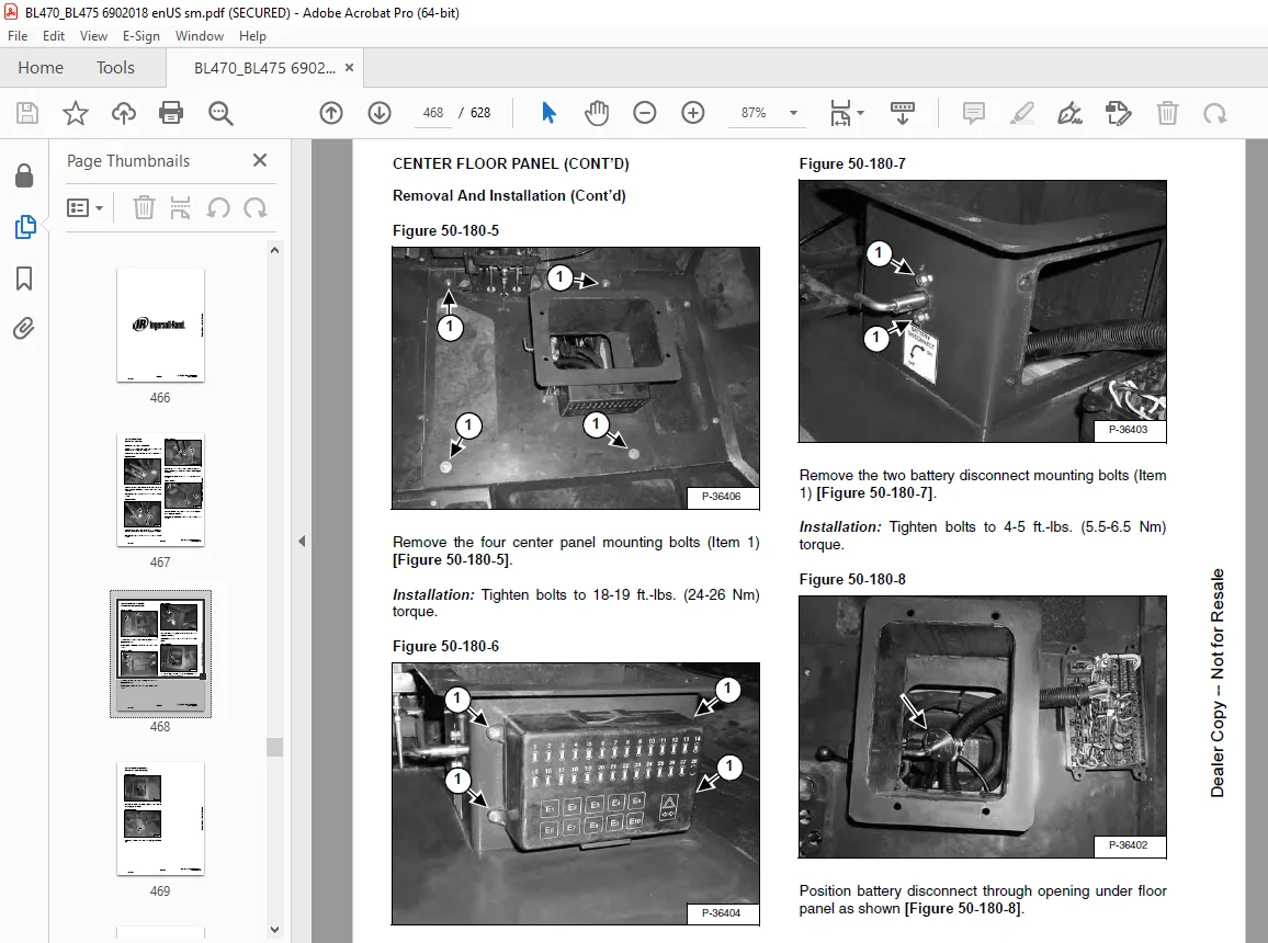
CENTER FLOOR PANEL……………………………………………….467
Removal And Installation………………………………………467
STABILIZER………………………………………………………471
Not Available At Time Of Printing………………………………471
FRONT AXLE PIVOT FRAME……………………………………………473
Not Available At Time Of Printing………………………………473
ELECTRICAL SYSTEM AND ANALYSIS………………………………………..475
ELECTRICAL SCHEMATICS…………………………………………….477
ELECTRICAL SYSTEM INFORMATION……………………………………..479
Troubleshooting Chart…………………………………………479
Description………………………………………………….480
Fuse Location………………………………………………..480
Relay Location……………………………………………….480
BATTERY…………………………………………………………481
Removal And Installation………………………………………481
Servicing The Electrical System………………………………..482
Using A Booster Battery (Jump Starting)…………………………483
ALTERNATOR………………………………………………………485
Adjusting The Alternator Belt………………………………….485
Description………………………………………………….485
Tests……………………………………………………….486
Alternator Output Test………………………………………..486
Full Field Test………………………………………………487
Alternator Regulator Test……………………………………..487
Alternator Regulator Test With Voltmeter………………………..488
Removal And Installation………………………………………489
Parts Identification………………………………………….490
Pulley Removal And Installation………………………………..491
Disassembly And Assembly………………………………………492
Rotor Continuity Test…………………………………………495
Stator Continuity Test………………………………………..495
Rectifier Continuity (Diode) Test………………………………496
Brush Length…………………………………………………496
STARTER…………………………………………………………497
Removal And Installation………………………………………497
Checking The Starter In The Loader……………………………..497
Parts Identification………………………………………….499
Disassembly………………………………………………….500
Inspection And Repair…………………………………………505
No Load Test…………………………………………………509
Assembly…………………………………………………….510
FRONT LIGHTS…………………………………………………….517
Bulb Removal And Installation………………………………….517
Housing Removal And Installation……………………………….519
TURN INDICATOR LIGHTS (FRONT)……………………………………..521
Bulb Removal And Installation………………………………….521
TURN INDICATOR LIGHTS (REAR)………………………………………523
Bulb Removal And Installation………………………………….523
CAB LIGHTS………………………………………………………525
Bulb Removal And Installation………………………………….525
Housing Removal And Installation……………………………….527
FUEL LEVEL SENDER………………………………………………..529
Removal And Installation………………………………………529
INSTRUMENT PANEL…………………………………………………531
Removal And Installation………………………………………531
ENGINE SERVICE………………………………………………………533
TROUBLESHOOTING………………………………………………….535
Chart……………………………………………………….535
ENGINE SPEED CONTROL……………………………………………..537
Removal And Installation………………………………………537
Cable Removal And Installation…………………………………538
MUFFLER…………………………………………………………541
Removal And Installation………………………………………541
AIR CLEANER……………………………………………………..543
Removal And Installation………………………………………543
RADIATOR………………………………………………………..545
Removal And Installation………………………………………545
ENGINE COMPONENTS AND TESTING……………………………………..547
Valve Clearance Adjustment…………………………………….547
Engine Compression Checking……………………………………548
Fuel Shut-Off Solenoid Removal And Installation………………….549
Checking Fuel Injection Pump…………………………………..550
Fuel Injection Pump Removal And Installation…………………….551
Fuel Injection Pump Timing…………………………………….553
Fuel Injector Nozzles…………………………………………554
Fuel Injector Nozzles Removal And Installation…………………..555
Fuel Injector Nozzles Check……………………………………556
ENGINE………………………………………………………….557
Removal And Installation………………………………………557
Mount Replacement…………………………………………….561
RECONDITIONING THE ENGINE-V2003T-EB (TURBO)…………………………563
Cylinder Head Removal And Installation………………………….563
Cylinder Head Disassembly And Assembly………………………….564
Cylinder Head Servicing……………………………………….565
Cylinder Head Top Clearance……………………………………565
Checking The Valve Guide………………………………………566
Reconditioning The Valve And Valve Seat…………………………567
Valve Spring…………………………………………………568
Rocker Arm And Shaft Checking………………………………….568
Timing Gearcase Cover Removal And Installation…………………..569
Idler Gear And Camshaft Removal And Installation…………………571
Servicing The Camshaft………………………………………..572
Servicing The Idle Gear And Shaft………………………………573
Timing Gears Checking Backlash…………………………………574
Fuel Camshaft Removal And Installation………………………….575
Fuel Camshaft Governor………………………………………..575
Crankshaft Gear Removal And Installation………………………..576
Oil Pump Removal And Installation………………………………576
Oil Pump Service……………………………………………..576
Checking Engine Oil Pressure…………………………………..577
Relief Valve…………………………………………………578
Piston And Connecting Rod Removal And Installation……………….579
Servicing The Piston And Connecting Rod…………………………581
Connecting Rod Alignment………………………………………582
Crankshaft And Bearings Removal And Installation…………………583
Servicing The Crankshaft And Bearings…………………………..584
Checking The Cylinder Bore…………………………………….588
Water Pump Disassembly And Assembly…………………………….589
FLYWHEEL HOUSING…………………………………………………591
Removal And Installation………………………………………591
FLYWHEEL………………………………………………………..593
Removal And Installation………………………………………593
Ring Gear Removal And Installation……………………………..593
DRIVE COUPLER……………………………………………………595
Removal And Installation………………………………………595
TURBOCHARGER…………………………………………………….597
Not Available At Time Of Printing………………………………597
SPECIFICATIONS………………………………………………………599
LOADER SPECIFICATIONS (BL 470)…………………………………….601
Loader Backhoe Dimensions……………………………………..601
LOADER SPECIFICATIONS (BL 475)…………………………………….602
Loader Backhoe Dimensions……………………………………..602
Performance………………………………………………….603
Controls…………………………………………………….603
Engine………………………………………………………603
Hydraulic System……………………………………………..604
Electrical…………………………………………………..604
Drive System…………………………………………………605
Capacities…………………………………………………..605
Tires……………………………………………………….605
ENGINE SPECIFICATIONS…………………………………………….607
Fuel Injection Nozzles………………………………………..607
Fuel Injection Pump…………………………………………..607
Cylinder Head………………………………………………..607
Valves………………………………………………………607
Valve Springs………………………………………………..608
Valve Timing…………………………………………………608
Rocker Arms………………………………………………….608
Camshaft…………………………………………………….608
Cylinders……………………………………………………608
Tappet………………………………………………………608
Piston Rings…………………………………………………609
Pistons……………………………………………………..609
Crankshaft…………………………………………………..609
Oil Pump…………………………………………………….609
Thermostat…………………………………………………..610
Connecting Rods………………………………………………610
Timing Gear………………………………………………….610
Cylinder Liner……………………………………………….610
Engine Bolt Torque……………………………………………611
Grinding Specifications for the Crankshaft………………………612
LOADER BACKHOE TORQUE…………………………………………….613
Specifications……………………………………………….613
TORQUE SPECIFICATIONS FOR BOLTS……………………………………615
Torque For General Metric Bolts………………………………..615
HYDRAULIC/HYDROSTATIC FLUID SPECIFICATIONS………………………….617
Specifications……………………………………………….617
CONVERSIONS……………………………………………………..619
Decimal And Millimeter Equivalents……………………………..619
U.S. To Metric Conversion……………………………………..619
PARTS MANAGER………………………………………………..621
SERVICE MANAGER X…………………………………………….621
SALES MANAGER………………………………………………..621
Revision No: BL-470/BL-475-1…………………………………..621
Date: 22 January 2002…………………………………………621
Product: Bobcat Loader Backhoe…………………………………621
Model: BL-470/BL-475………………………………………….621
Manual No: 6902018 (12-02)…………………………………….621
PARTS MANAGER………………………………………………..623
SERVICE MANAGER X…………………………………………….623
SALES MANAGER………………………………………………..623
Revision No: BL-470/BL-475-2…………………………………..623
Date: 1 April 2003……………………………………………623
Product: Loader Backhoe……………………………………….623
Model: BL-470/BL-475………………………………………….623
Manual No: 6902018 (12-02)…………………………………….623
PARTS MANAGER………………………………………………..625
SERVICE MANAGER X…………………………………………….625
SALES MANAGER………………………………………………..625
Revision No: BL-470/BL-475-3…………………………………..625
Date: 1 June 2003…………………………………………….625
Product: Loader Backhoe……………………………………….625
Model: BL-470/BL-475………………………………………….625
Manual No: 6902018 (12-02)…………………………………….625
SERVICE MANUAL REVISIONS …………………………………………….621
BL-470/BL475-1…………………………………………………..621
BL470/BL-475-2 ………………………………………………….623
BL-470/BL475-3 ………………………………………………….625
BL470/BL-475-4…………………………………………………..627
Need help? Contact: [email protected]
https://vimeo.com/842140709?share=copy
DESCRIPTION:
BOBCAT BL-470 BL-475 INGERSOLL RAND Service Manual PDF DOWNLOAD
FOREWORD
This manual is for the Ingersoll Rand loader mechanic. It provides necessary servicing and adjustment
procedures for the Ingersoll Rand loader and its component parts and systems. Refer to the Operation
& Maintenance Manual for operating instructions, Starting procedure, daily checks, etc.
SAFETY INSTRUCTIONS FOR INGERSOLL-RAND LOADER BACKHOE AND ATTACHMENTS
SAFE OPERATION IS THE OPERATOR’S RESPONSIBILITY
Carefully follow the operating and maintenance instructions in this manual.
- The Ingersoll-Rand loader backhoe is highly maneuverable and compact. It is rugged and useful under a wide variety of conditions. This presents an operator with hazards associated with off-highway, rough terrain applications, common with Ingersoll-Rand loader backhoe usage.
- The Ingersoll-Rand loader backhoe has an internal combustion engine with resultant heat and exhaust. All exhaust gases can kill or cause illness, so use the loader backhoe with adequate ventilation. The loader backhoe has a spark arrestor exhaust system or muffler which is required for operation in certain areas.
- The dealer explains the capabilities and restrictions of the Ingersoll-Rand loader backhoe and attachments for each application. The dealer demonstrates the safe operation according to Ingersoll-Rand instructional materials, which are also available to operators. The dealer can also identify unsafe modifications or use of unapproved attachments. The attachments and buckets are designed for a Rated Operating Capacity (some have restricted lift heights) and secure fastening to the Ingersoll-Rand loader backhoe. The user must check with the dealer, or Ingersoll-Rand literature, to determine safe loads of materials of specified densities for the loader backhoe-attachment combination.
The following publications and training materials provide information on the safe use and maintenance of the Ingersoll-Rand loader backhoe and attachments:
PLEASE NOTE:
- This is the same manual used by the dealers to diagnose and troubleshoot your vehicle
- You will be directed to the download page as soon as the purchase is completed. The whole payment and downloading process will take anywhere between 2-5 minutes
- Need any other service / repair / parts manual, please feel free to contact [email protected] . We still have 50,000 manuals unlisted
G.P