Bobcat L28 Small Articulated Loader Service Manual SN B4LD11001 & Above – PDF DOWNLOAD
$30.95
Bobcat L28 Small Articulated Loader Service Manual SN B4LD11001 & Above – PDF DOWNLOAD
Description
Bobcat L28 Small Articulated Loader Service Manual SN B4LD11001 & Above – PDF DOWNLOAD
FILE DETAILS:
Bobcat L28 Small Articulated Loader Service Manual SN B4LD11001 & Above – PDF DOWNLOAD
Language : English
Pages : 581
Downloadable : Yes
File Type : PDF
IMAGES PREVIEW OF THE MANUAL:
DESCRIPTION:
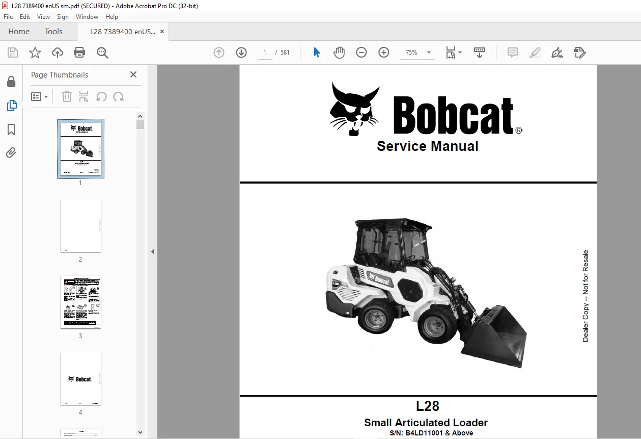
Bobcat L28 Small Articulated Loader Service Manual SN B4LD11001 & Above – PDF DOWNLOAD
FOREWORD:
This manual is for the Bobcat loader mechanic. It provides necessary servicing and adjustment procedures for the Bobcat loader and its component parts and systems. Refer to the Operation & Maintenance Manual for operating instructions, starting procedure, daily checks, etc.
SAFETY INSTRUCTIONS:
The following publications provide information on the safe use and maintenance of the Bobcat machine and attachments:
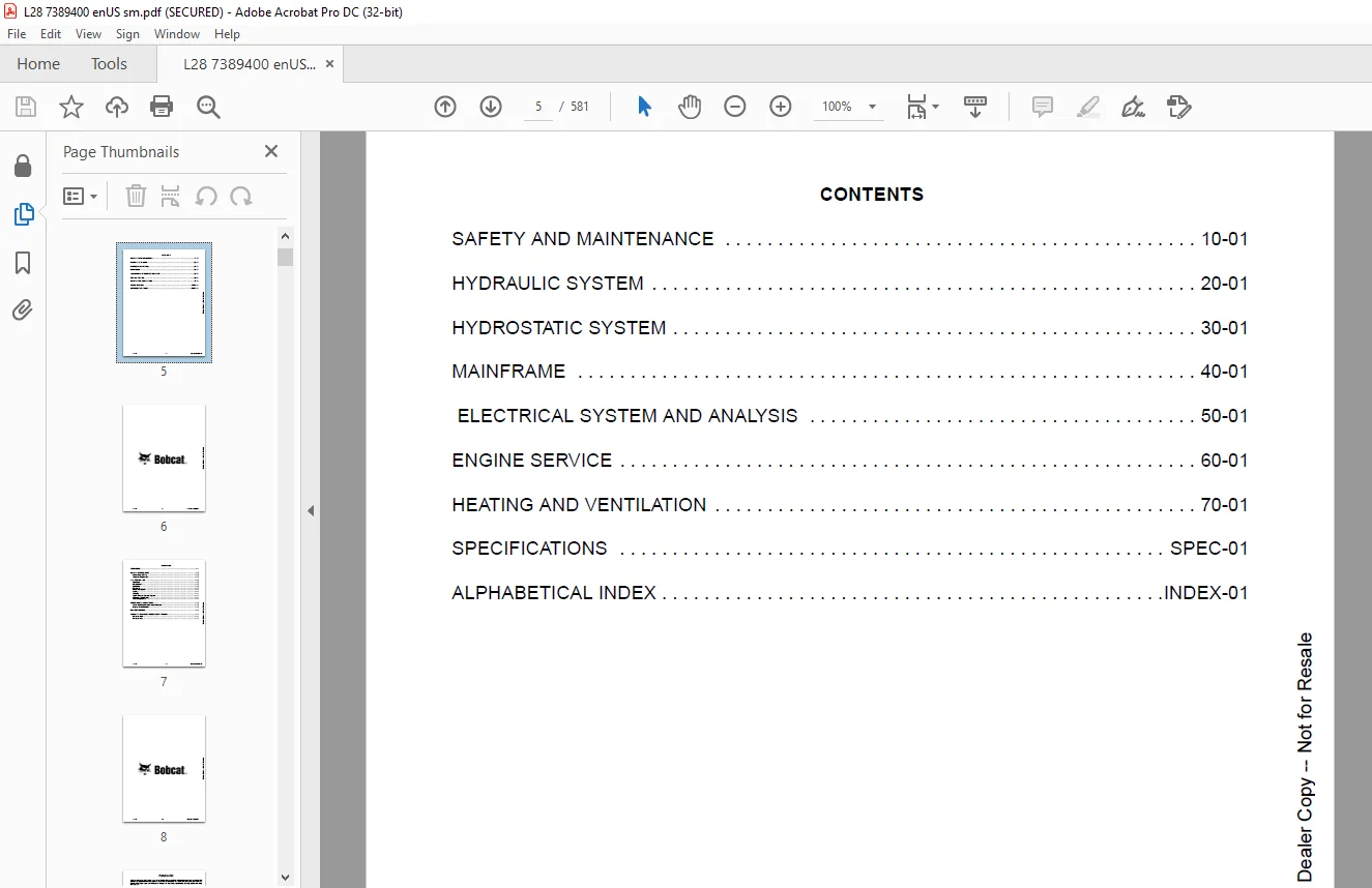
TABLE OF CONTENTS:
Bobcat L28 Small Articulated Loader Service Manual SN B4LD11001 & Above – PDF DOWNLOAD
MAINTENANCE SAFETY 3
FOREWORD 7
FOREWORD 9
SAFETY INSTRUCTIONS 11
Call Before You Dig 12
Silica Dust Exposure 12
FIRE PREVENTION 12
Operation 12
Maintenance 12
Operation 12
Electrical 13
Hydraulic System 13
Fueling 13
Starting 13
Spark Arrester Exhaust System 13
Welding And Grinding 13
Fire Extinguishers 13
SERIAL NUMBER LOCATIONS 14
Small Articulated Loader Serial Number 14
Engine Serial Number 14
DELIVERY REPORT 15
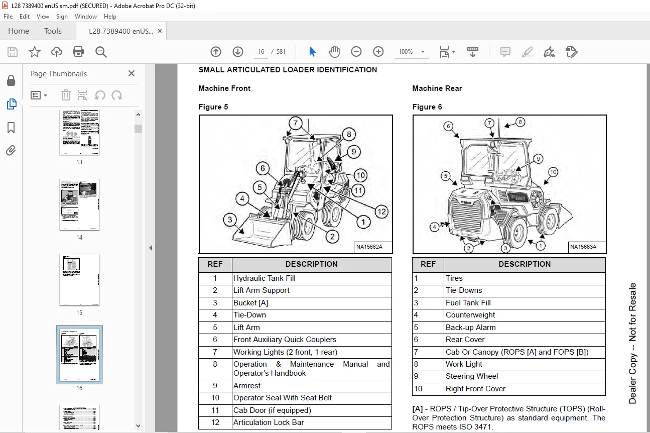
Machine Front 16
Machine Rear 16
SAFETY AND MAINTENANCE 17
LIFTING AND BLOCKING THE SMALL ARTICULATED LOADER 19
Lifting And Blocking Procedure 19
LIFT ARM SUPPORT 21
Lift Arm Support Description 21
Installing Lift Arm Support 21
Removing Lift Arm Support 22
OPERATOR ENCLOSURE 23
Operator Enclosure Description 23
TRANSPORTING THE MACHINE 25
Loading And Unloading 25
Fastening 25
TOWING THE MACHINE 27
Towing Machine 27
REMOTE START TOOL (SERVICE TOOL) KIT – 7217666 29
Remote Start Tool Description 29
Remote Start Tool – 7022042 30
Service Tool Harness – 6689747 31
Computer Service Tool Harness – 6689746 32
SERVICE SCHEDULE 33
Maintenance Intervals 33
ENGINE AIR CLEANER 37
Replacing Engine Air Cleaner Filters 37
ENGINE COOLING SYSTEM 39
Cleaning Engine Cooling System 39
Checking And Adding Coolant 39
Replacing Coolant 41
FUEL SYSTEM 43
Fuel Specifications 43
Biodiesel Blend Fuel 43
Filling The Fuel Tank 44
Removing Water From Fuel Filter 45
Replacing Fuel Filter 46
Removing Air From The Fuel System 47
ENGINE LUBRICATION SYSTEM 49
Checking And Adding Engine Oil 49
Engine Oil Chart 49
Removing And Replacing Oil And Filter 50
HYDRAULIC / HYDROSTATIC SYSTEM 53
Checking And Adding Hydraulic Fluid 53
Hydraulic Fluid Chart 53
Replacing Hydraulic Fluid 54
Replacing Hydraulic / Hydrostatic Filter 57
BOB-TACH (HAND LEVER) 59
Inspecting And Maintaining Hand Lever Bob-Tach 59
BOB-TACH (POWER) 61
Inspecting And Maintaining Power Bob-Tach 61
MACHINE LUBRICATION 63
Lubricating Grease Fittings 63
Lubrication Locations 63
TIRE MAINTENANCE 65
Checking Wheel Nut Torque 65
Mounting Tires 65
MACHINE STOARGE AND RETURN TO SERVICE 67
Extended Storage Procedure 67
Returning The Machine To Service 67
STOPPING THE ENGINE AND LEAVING THE MACHINE 69
Stopping The Engine And Leaving The Machine 69
EMERGENCY EXIT 71
Performing An Emergency Exit 71
SEAT BELT 73
Inspecting And Maintaining The Seat Belt 73
SPARK ARRESTER 75
Cleaning Spark Arrester Muffler 75
HYDRAULIC SYSTEM 77
HYDRAULIC / HYDROSTATIC SCHEMATICS 81
HYDRAULIC SYSTEM INFORMATION 85
Glossary Of Hydraulic / Hydrostatic Symbols 85
Troubleshooting The Hydraulic System 89
Articulation Joint Hydraulic Hose Routing 90
LIFT CYLINDER 91
Testing Lift Cylinder 91
Removing And Installing Lift Cylinder 92
Parts Identification 94
Disassembling Lift Cylinder 95
Assembling Lift Cylinder 97
TILT CYLINDER 101
Testing Tilt Cylinder 101
Removing And Installing Tilt Cylinder 102
Parts Identification 104
Disassembling Tilt Cylinder 105
Assembling Tilt Cylinder 107
LEVELING CYLINDER 111
Testing Leveling Cylinder 111
Removing And Installing Leveling Cylinder 112
Parts Identification 115
Disassembling Leveling Cylinder 116
Assembling Leveling Cylinder 118
TELESCOPIC CYLINDER 121
Testing Telescopic Cylinder 121
Removing And Installing Telescopic Cylinder 122
Parts Identification 125
Disassembling Telescopic Cylinder 126
Assembling Telescopic Cylinder 128
STEERING CYLINDER 131
Testing Steering Cylinder 131
Removing And Installing Steering Cylinder 132
Parts Identification 134
Disassembling Steering Cylinder 135
Assembling Steering Cylinder 137
MAIN RELIEF VALVE 141
Main Relief Valve Description 141
Testing Main Relief Valve 141
Removing And Installing Main Relief Valve 142
Adjusting Main Relive Valve 143
PORT RELIEF VALVE 145
Port Relief Valve Description 145
Testing Lift Port Relief Valve (Base End) 145
Testing Lift Port Relief Valve (Rod End) 146
Tilt Port Relief Valve Testing 147
HYDRAULIC CONTROL VALVE 149
Hydraulic Control Valve Description 149
Removing And Installing Hydraulic Control Valve 150
Identification Chart 154
Disassembling Hydraulic Control Valve 155
Disassembling And Assembling End Valve Section 157
Disassembling And Assembling End Valve Section 158
Disassembling And Assembling Lift Valve Section 159
Disassembling And Assembling Tilt Valve Section 164
Disassembling And Assembling Telescopic Valve Section 168
Disassembling And Assembling Auxiliary Valve Section 172
Assembling Hydraulic Control Valve 177
PILOT MANIFOLD 181
Pilot Manifold Description 181
Removing And Installing Pilot Manifold 181
Parts Identification 183
Disassembling And Assembling Pilot Manifold 184
LIFT ARM CONTROL (BYPASS) 187
Lift Arm Control (Bypass) Description 187
Testing Lift Arm Control (Bypass) 187
IMPLEMENT PUMP 189
Implement Pump Description 189
Testing Lift, Tilt, Telescopic, And Auxiliary Sections 189
Removing And Installing Implement Pump 191
Parts Identification 192
Disassembling And Assembling Implement Pump 193
STEERING CONTROL UNIT 199
Steering Control Unit Description 199
Removing And Installing Steering Control Unit 199
Parts Identification 200
Disassembling And Assembling Steering Control Unit 201
HYDRAULIC / HYDROSTATIC FILTER 205
Hydraulic / Hydrostatic Filter Description 205
Removing And Installing Housing 205
JOYSTICK 207
Joystick Description 207
Removing And Installing Handle 207
HYDRAULIC FLUID RESERVOIR 209
Hydraulic Fluid Reservoir Description 209
Removing And Installing Hydraulic Reservoir 209
Removing And Installing Hydraulic Fluid Screen 212
OIL COOLER 213
Oil Cooler Description 213
Removing And Installing Oil Cooler 213
DRIVE PEDAL 215
Removing And Installing Drive Pedal 215
Disassembling And Assembling Drive Pedal 218
POWER BOB-TACH BLOCK 221
Power Bob-Tach Description 221
Removing And Installing Power Bob-Tach 221
Disassembling And Assembling Power Bob-Tach 223
AUXILIARY HYDRAULIC COUPLER BLOCK 229
Coupler Block Description 229
Removing And Installing Coupler Block 229
Disassembling And Assembling Coupler Block 230
TELESCOPIC MANIFOLD 233
Telescopic Manifold Description 233
Removing And Installing Telescopic Manifold 233
Disassembling And Assembling Telescopic Manifold 236
TRACTION ASSIST 241
Traction Assist Description 241
Removing And Installing Traction Assists 241
Disassembling And Assembling Traction Assist 245
CASE DRAIN MANIFOLD 249
Case Drain Manifold Description 249
Removing And Installing Case Drain Manifold 249
HYDROSTATIC SYSTEM 251
HYDROSTATIC SYSTEM INFORMATION 253
Troubleshooting 253
Hydrostatic System Description 254
HYDROSTATIC MOTOR (SAPR BRAKE) 255
Hydrostatic Motor (SAPR Brake) Description 255
Removing And Installing Hydrostatic Motor (SAPR Brake) 255
Parts Identification 258
Disassembling Hydrostatic Motor (SAPR Brake) 259
Assembling Hydrostatic Motor (SAPR Brake) 266
HYDROSTATIC MOTOR 273
Hydrostatic Motor Description 273
Removing And Installing Hydrostatic Motor 273
Parts Identification 278
Disassembling Hydrostatic Motor 279
Assembling Hydrostatic Motor 284
HYDROSTATIC PUMP 289
Hydrostatic Pump Description 289
Removing And Installing Hydrostatic Pump 289
Parts Identification 292
Disassembling And Assembling Hydrostatic Pump 293
TURF TRACTION MANIFOLD 305
Turf Traction Manifold Description 305
Removing And Installing Turf Traction Manifold 305
Disassembling And Assembling Turf Traction Manifold 307
MAINFRAME 309
ENCLOSURE 311
Removing And Installing Enclosure 311
Removing And Installing Front Window 315
Removing And Installing Wiper Motor 316
Removing And Installing Rear Window 317
Removing And Installing Side Window 317
Removing And Installing Door 318
Removing And Installing Armrest 318
Removing And Installing Dash Cover 319
Removing And Installing Steering Wheel 320
Removing And Installing Operator Seat 320
Removing And Installing Floor Panel 321
BOB-TACH HAND LEVER 323
Bob-Tach Hand Lever Description 323
Removing And Installing Bob-Tach Hand Lever 323
Disassembling And Assembling Bob-Tach Hand Lever 324
Disassembling And Assembling Bob-Tach Hand Lever 325
BOB-TACH POWER 327
Removing And Installing Bob-Tach Power 327
Disassembling And Assembling Bob-Tach Power 329
PIVOT LINK 331
Removing And Installing Pivot Link 331
LIFT ARM 333
Removing And Installing Lift Arm 333
TELESCOPIC LIFT ARM 335
Removing And Installing Telescopic Lift Arm 335
Inspecting Lift Arm Wear Pads – Extended 338
Inspecting Lift Arm Wear Pads – Retracted 339
REAR COVER 341
Removing And Installing Rear Cover 341
RIGHT REAR COVER 343
Removing And Installing Right Rear Cover 343
LEFT REAR COVER 345
Removing And Installing Left Rear Cover 345
CENTER COVER 347
Removing And Installing Center Cover 347
PUMP COVER 349
Removing And Installing Pump Cover 349
RIGHT FRONT COVER 351
Removing And Installing Right Front Cover 351
RIGHT CORNER COVER 353
Removing And Installing Right Corner Cover 353
LEFT FRONT COVER 355
Removing And Installing Left Front Cover 355
COUNTERWEIGHT 357
Removing And Installing Counterweight 357
FUEL TANK 359
Removing And Installing Fuel Tank 359
Removing And Installing Fuel Level Sender 360
ENCLOSURE BUMPERS 361
Removing And Installing Enclosure Bumpers 361
REAR GRILLE 363
Removing And Installing Rear Grille 363
ARTICULATION PIN 365
Removing And Installing Articulation Pin 365
ELECTRICAL SYSTEM AND ANALYSIS 367
ELECTRICAL SCHEMATICS 369
ELECTRICAL SYSTEM INFORMATION 382
Glossary Of Electrical Symbols 382
Electrical System Troubleshooting Chart 385
Electrical System Description 386
Fuse And Relay Location / Identification 387
BATTERY 390
Battery Maintenance 390
Maintaining Battery Charge Level 390
Battery Service During Machine Storage 390
Testing Battery 391
Charging Battery 391
Removing And Installing The Battery 392
Using A Booster Battery (Jump Starting) 393
ALTERNATOR 396
Adjusting Belt 396
Replacing Belt 396
Charging System Inspection 398
Testing Alternator Voltage 399
Removing And Installing Alternator 399
Parts Identification 401
STARTER 402
Testing Starter 402
Removing And Installing Starter 403
Parts Identification 404
INSTRUMENT PANEL 406
Removing And Installing Display Panel 406
LIGHTS 408
Removing And Installing Front lights 408
Removing And Installing Rear Light 408
GATEWAY CONTROLLER 410
Controller Description 410
Removing And Installing Gateway Controller 410
DIAGNOSTIC SERVICE CODES 414
Viewing Service Codes 414
Service Codes List 414
OPERATING INTERLOCK CONTROL SYSTEM 418
Operating Interlock Control System Description 418
Operating The Operator Interlock Control System 418
Inspecting The Operating Interlock Control System 419
Inspecting Deactivation Of The Auxiliary Hydraulics System (Engine STOPPED – Key On) 419
Inspecting The Armrest Sensor (Engine RUNNING) 419
Inspecting The Travel Pedal Interlocks (Engine RUNNING) 419
Inspecting The Lift Arm Bypass Control 420
ARMREST SENSOR 422
Armrest Sensor Description 422
Removing And Installing Armrest Sensor 422
SERVICE PC (LAPTOP COMPUTER) 424
Connecting The Remote Start Tool (Service Tool) 424
ELECTRIC COOLING FAN 426
Electric Cooling Fan Description 426
Removing And Installing Electric Cooling Fan 426
BACK-UP ALARM 428
Back-up Alarm Description 428
Inspecting Back-up Alarm 428
Troubleshooting Back-up Alarm 429
Removing And Installing Back-up Alarm 430
FRONT HORN 432
Removing And Installing Front Horn 432
Troubleshooting 433
FUEL LEVEL SENDER 434
Removing And Installing Fuel Level Sender 434
Testing Fuel Level Sender 435
KEY SWITCH 436
Removing And Installing Key Switch 436
BATTERY DISCONNECT SWITCH 438
Battery Disconnect Switch Description 438
Removing And Installing Battery Disconnect Switch 438
ENGINE SERVICE 440
ENGINE INFORMATION 442
Engine Description 442
Specifications 443
Crankshaft Re-Grind Data 449
Torque For Kubota® Metric Bolts 450
Troubleshooting 451
Removing And Installing Engine 452
Checking Compression 460
ENGINE SPEED CONTROL (LEVER) 462
Removing And Installing Engine Speed Control (Lever) 462
Calibrating Engine Speed Control 463
MUFFLER 464
Removing Muffler 464
Installing Muffler 465
EXHAUST PIPE 466
Removing And Installing Exhaust Pipe 466
AIR CLEANER 468
Removing And Installing Air Cleaner 468
ENGINE COOLING SYSTEM 470
Removing And Installing Coolant Recovery Tank 470
Removing And Installing Radiator 471
Removing And Installing Fan And Pulley 472
Removing And Installing Water Pump 473
Assembling And Disassembling Water Pump 473
Removing And Installing Thermostat Housing 474
Checking Thermostat 474
LUBRICATION SYSTEM 476
Removing And Installing Oil Pan 476
Removing And Installing Oil Pump 476
Inspecting Oil Pump 477
Testing Engine Oil Pressure 478
FUEL SYSTEM 480
Checking Fuel Shutoff Solenoid 480
Removing And Installing Fuel Shutoff Solenoid 481
Checking Fuel Injection Pump 482
Removing And Installing Fuel Injection Pump 483
Timing Fuel Injection Pump 487
Removing And Installing Fuel Camshaft 488
Fuel Camshaft Governor 489
Removing And Installing Fuel Injector 490
Checking Fuel Injector Nozzle Pressure 492
Checking Nozzle Spray Condition 493
Valve Seat Tightness 493
CYLINDER HEAD 494
Testing Glow Plugs 494
Removing And Installing Glow Plugs 494
Adjusting Valve Clearance 495
Checking Valve Timing 496
Removing And Installing Cylinder Head 497
Disassembling And Assembling Cylinder Head 502
Servicing Cylinder Head 502
Clearance Cylinder Head Top 503
Checking Valve Guide 503
Removing And Installing Valve Guide 504
Reconditioning The Valve And Valve Seat 505
Checking Valve Spring 506
Checking Valve Tappets 507
Checking Rocker Arm And Shaft 508
Checking Push Rod Alignment 508
CRANKSHAFT AND PISTONS 510
Removing And Installing Piston And Connecting Rod 510
Servicing Piston And Connecting Rod 512
Checking Cylinder Bore 514
Connecting Rod Alignment 515
Removing And Installing Crankshaft Gear 516
Removing And Installing Crankshaft And Bearings 517
Servicing Crankshaft And Bearings 520
CAMSHAFT AND TIMING GEARS 524
Removing And Installing Timing Gearcase Cover 524
Checking Timing Gears Backlash 526
Removing And Installing Idler Gear And Shaft 526
Servicing Camshaft 527
Servicing Idler Gear And Shaft 529
FLYWHEEL AND HOUSING 530
Removing And Installing Hydrostatic Pump Coupler 530
Removing And Installing Flywheel 532
Removing And Installing Flywheel Ring Gear 532
HEATING AND VENTILATION 534
REGULAR MAINTENANCE 536
Maintaining Fresh Air / Recirculation Filter 536
TROUBLESHOOTING 538
Blower Motor Does Not Operate 538
Blower Motor Operates Normally, But Air Flow Is Insufficient 538
Electrical System 539
HEATER UNIT 540
Removing And Installing Heater Unit 540
HEATER VALVE 542
Removing And Installing Heater Valve 542
HEATER COIL 544
Removing And Installing Heater Coil 544
BLOWER FAN 546
Removing And Installing Blower Fan 546
SPECIFICATIONS 548
SMALL ARTICULATED LOADER SPECIFICATIONS 550
Machine Dimensions 550
Performance Specifications 552
Controls Specifications 552
Engine Specifications 553
Hydraulic System Specifications 554
Electrical System Specifications 555
Drive System Specifications 555
Capacities Specifications 556
Tire Specifications 556
TECHNICAL SERVICE GUIDE SPECIFICATIONS 558
Engine 558
Engine Torques 558
Small Articulated Loader Torques 558
Cooling System 558
TORQUE SPECIFICATION FOR BOLTS 560
Torque For General SAE Bolts 560
Torque For General Metric Bolts 561
HYDRAULIC CONNECTION SPECIFICATIONS 562
O-ring Face Seal Connection 562
Straight Thread O-ring Fitting 562
Tubelines And Hoses 563
Flare Fitting 563
O-ring Flare Fitting 564
Port Seal Fitting 566
Push To Connect Fittings 567
HYDRAULIC FLUID SPECIFICATIONS 570
Specifications 570
CONVERSIONS 572
Decimal And Millimeter Equivalent Chart 572
U S To Metric Conversion Chart 573
SERVICE TOOLS REQUIRED 574
Remote Start Tools 574
Hydraulic Tools 575
Engine Tools 577
Electrical Tools 577
ALPHABETICAL INDEX 578
Customer Support: [email protected]
PLEASE NOTE:
- This is the SAME manual used by the dealers to troubleshoot any faults in your vehicle. This can be yours in 2 minutes after the payment is made.
- Contact us at [email protected] should you have any queries before your purchase or that you need any other service / repair / parts operators manual.
S.V