Bobcat LOAD EXCAVATOR ZX75 Ingersoll Rand SERVICE MANUAL – PDF DOWNLOAD
$34.95
Bobcat LOAD EXCAVATOR ZX75 Ingersoll Rand SERVICE MANUAL – PDF DOWNLOAD
Description
Bobcat LOAD EXCAVATOR ZX75 Ingersoll Rand SERVICE MANUAL – PDF DOWNLOAD
FILE DETAILS:
Bobcat LOAD EXCAVATOR ZX75 Ingersoll Rand SERVICE MANUAL – PDF DOWNLOAD
Language : English
Pages :804
Downloadable : Yes
File Type : PDF
TABLE OF CONTENTS:
Bobcat LOAD EXCAVATOR ZX75 Ingersoll Rand SERVICE MANUAL – PDF DOWNLOAD
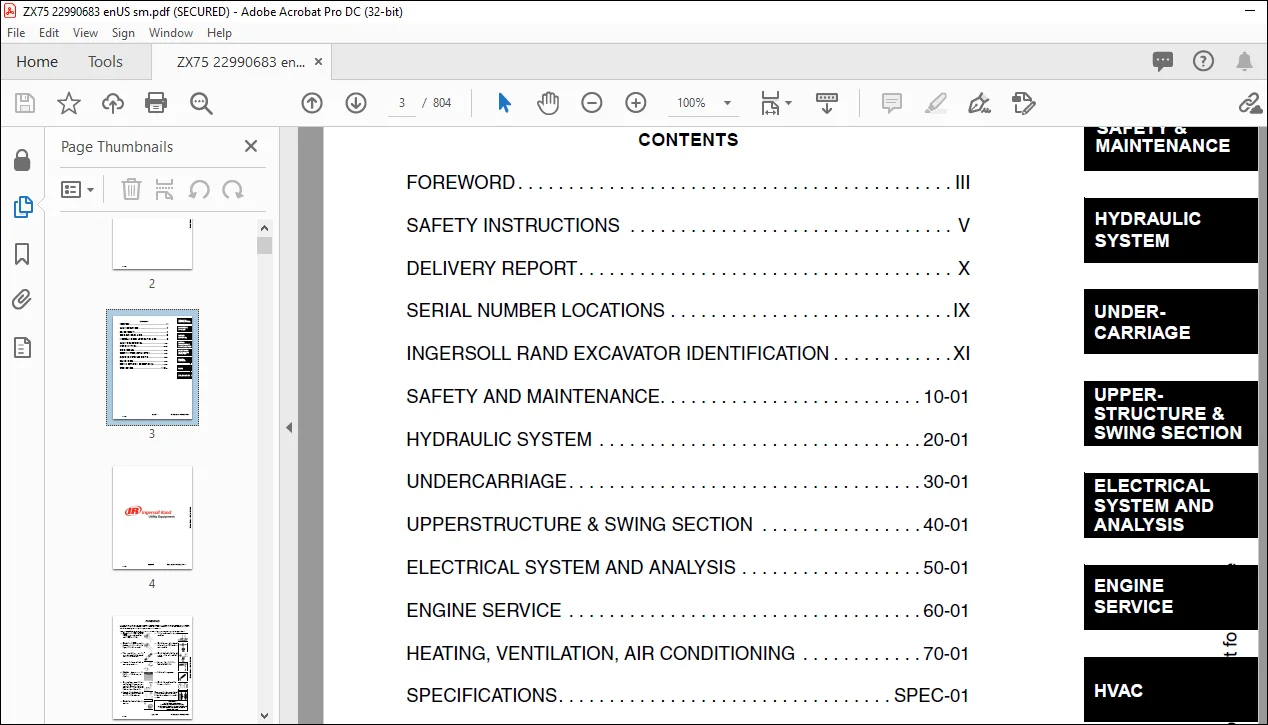
CONTENTS 3
FOREWORD 5
SAFETY INSTRUCTIONS 7
Fire Prevention 9
SERIAL NUMBER LOCATIONS 11
Excavator Serial Number 11
Engine Serial Number 11
DELIVERY REPORT 12
INGERSOLL RAND EXCAVATOR IDENTIFICATION 13
MAINTENANCE SAFETY 15
SPECIFICATIONS 17
HYDRAULIC EXCAVATOR SPECIFICATIONS 19
Machine Dimensions 19
Performance 20
Controls 20
Engine 21
Electrical 21
Hydraulic System 21
Hydraulic System 22
Hydraulic Cycle Times 22
Swing System 22
Hydraulic Cylinders 22
Drive System 23
Brakes 23
Undercarriage 23
Track 23
Capacities 24
Digging Force 24
EXCAVATOR BOLT TORQUE 25
Specifications 25
TORQUE SPECIFICATIONS FOR BOLTS 27
Torque For General SAE Bolts 27
Torque For General Metric Bolts 27
HYDRAULIC FLUID SPECIFICATIONS 29
Specifications 29
FUEL, COOLANT AND LUBRICANTS 31
Chart 31
CONVERSIONS 33
Decimal And Millimeter Equivalents 33
U S To Metric Conversion 34
SAFETY AND MAINTENANCE 35
LIFTING AND BLOCKING THE EXCAVATOR 37
Procedure 37
LIFTING THE EXCAVATOR 39
Procedure 39
OPERATOR CAB 41
Description 41
Entering And Exiting The Excavator 41
Raising And Lowering The Left Console 41
Emergency Exit 42
TRANSPORTING THE EXCAVATOR 43
REAR COVER 45
Opening And Closing The Rear Cover 45
RIGHT SIDE COVER 47
Opening And Closing The Right Side Cover 47
SERVICE SCHEDULE 49
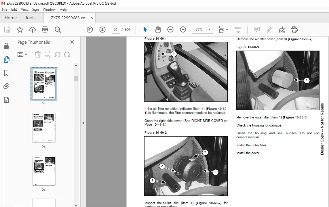
AIR CLEANER 51
Daily Check 51
Replacing The Filters 51
FRESH AIR FILTER 55
Removal And Installation 55
FRESH AIR FILTER 57
Removal And Installation 57
FUEL SYSTEM 59
Fuel Specifications 59
Filling The Fuel Tank 59
Pre-Filter Removal And Installation 60
Fuel Filter Removal And Installation 61
Draining The Fuel Tank 62
ENGINE LUBRICATION SYSTEM 63
Checking Engine Oil 63
Replacing Oil And Filter 64
HYDRAULIC SYSTEM 67
Checking And Adding Hydraulic Oil 67
Replacing The Hydraulic Oil 68
Hydraulic Filter Removal 69
Hydraulic Filter Installation 70
Hydraulic Filter Removal 72
Hydraulic Filter Installation 73
Hydraulic Filter Installation 74
Diagnostic Couplers 75
LUBRICATION OF THE EXCAVATOR 77
TRAVEL MOTOR 81
Checking Oil Level 81
Draining The Travel Motor 81
ALTERNATOR BELT 83
Adjusting Belt Tension 83
FAN/FUEL PUMP BELT 85
Adjusting Belt Tension 85
AIR CONDITIONING COMPRESSOR BELT 87
Adjusting Belt Tension 87
CAB TILT PROCEDURE 89
Installing The Cab Tilt Hinges 89
Tilting The Cab 90
HYDRAULIC SYSTEM 97
HYDRAULIC SYSTEM INFORMATION 103
Troubleshooting Chart 103
Description 108
BOOM CYLINDER 111
Testing 111
Removal And Installation 113
Parts Identification 117
Disassembly 118
Assembly 123
ARM CYLINDER 129
Testing 129
Removal And Installation 129
Parts Identification 133
Disassembly 134
Assembly 139
BOOM OFFSET CYLINDER 145
Testing 145
BOOM OFFSET CYLINDER 148
Removal And Installation 148
Parts Identification 152
Disassembly 153
Assembly 157
BUCKET CYLINDER 165
Testing 165
Removal And Installation 165
Parts Identification 169
Disassembly 170
Assembly 174
BLADE CYLINDER 181
Testing 181
Removal And Installation 182
Parts Identification 184
Disassembly 185
Assembly 190
RELIEF VALVES 197
Description 197
Testing The Three Spool Control Valve Main Relief Valve 198
Adjusting The Three Spool Control Valve Main Relief Valve 198
PORT RELIEF VALVES 199
Adjustment Procedure 199
PRESSURE REDUCING VALVE 201
Description 201
Testing 201
PRESSURE REDUCING VALVE 202
Adjustment 202
DUMP VALVE 203
Description 203
Testing 203
Adjustment 203
Removal And Installation 204
Parts Identification 205
Disassembly And Assembly 206
SIX SPOOL HYDRAULIC CONTROL VALVE 211
Removal And Installation 211
Control Valve Identification 215
Disassembly And Assembly 216
Left Travel And Right Travel Valve Section Disassembly And Assembly 219
Boom, Arm, Bucket And Auxiliary Valve Section Disassembly And Assembly 222
Inlet Valve Section Disassembly And Assembly 227
THREE SPOOL HYDRAULIC CONTROL VALVE 229
Removal And Installation 229
Parts Identification 231
Disassembly And Assembly 232
Boom Offset And Blade Valve Section Disassembly And Assembly 234
Inlet/Upperstructure Swing Valve Section Disassembly And Assembly 238
HYDRAULIC PISTON PUMP 243
Hydraulic Pump Work Sheet 243
HYDRAULIC PISTON PUMP 246
Testing Information 246
Pump Testing 247
Removal And Installation 255
Coupler Removal And Installation 257
Torque Limiter Valve Parts Identification 258
Torque Limiter Valve Removal and Installation 259
Torque Limiter Valve Disassembly 260
Torque Limiter Valve Assembly 264
Initial Torque Limiter Valve Setting 268
Pump Control Parts Identification 270
Pump Control Removal And Installation 271
Pump Control Disassembly And Assembly 272
Parts Identification 277
Disassembly 278
Assembly 287
HYDRAULIC GEAR PUMP 297
Removal And Installation 297
Parts Identification 299
Disassembly 300
Assembly 303
ACCUMULATOR 307
Description 307
Removal And Installation 307
TRAVEL MOTOR 309
Removal And Installation 309
Parts Identification 310
Disassembly 311
Assembly 328
SWIVEL JOINT 347
Removal And Installation 347
Parts Identification 349
Disassembly And Assembly 350
SWING MOTOR 353
Removal And Installation 353
Parts Identification 355
Disassembly 356
Assembly 362
SWING MOTOR DRIVE CARRIER 369
Removal And Installation 369
Parts Identification 371
Disassembly 372
Assembly 381
SWING BRAKE VALVE 395
Removal And Installation 395
Parts Identification 396
Disassembly And Assembly 397
SWING BRAKE RELEASE VALVE 399
Removal And Installation 399
Parts Identification 400
Disassembly And Assembly 401
JOYSTICK CONTROL PATTERN SELECTOR VALVE 403
Removal And Installation 403
Parts Identification 404
Disassembly And Assembly 405
JOYSTICK LOCKOUT/TWO SPEED VALVE 407
Removal And Installation 407
Parts Identification 409
Disassembly And Assembly 410
RIGHT CONTROL LEVER (JOYSTICK) 415
Testing 415
Handle Removal And Installation 416
Removal And Installation 417
Parts Identification 419
Disassembly And Assembly 420
LEFT CONTROL LEVER (JOYSTICK) 425
Testing 425
Handle Removal And Installation 426
Removal And Installation 427
Parts Identification 429
Disassembly and Assembly 430
TRAVEL LEVER/FOOT PEDAL VALVE 435
Left Travel Lever/Foot Pedal Valve Removal And Installation 435
Right Travel Lever/Foot Pedal Valve Removal And Installation 436
Parts Identification 438
Disassembly And Assembly 439
HYDRAULIC FILTER MOUNT 443
Removal And Installation 443
HYDRAULIC RESERVOIR 445
Removal And Installation 445
SECONDARY FRONT AUXILIARY VALVE 453
Removal And Installation 453
Parts Identification 454
Disassembly And Assembly 455
HYDRAULIC BREAKER APPLICATION VALVE 459
Removal And Installation 459
Parts Identification 460
Disassembly And Assembly 461
AUXILIARY HYDRAULIC FLOW CONTROL VALVE 463
Removal And Installation 463
Parts Identification 464
Disassembly And Assembly 465
AUXILIARY HYDRAULIC FLOW CONTROL/HYDRAULIC BREAKER APPLICATION VALVE 467
Removal And Installation 467
Parts Identification 468
Disassembly And Assembly 469
BLADE VALVE 473
Removal And Installation 473
Parts Identification 474
Disassembly And Assembly 475
BLADE FLOAT VALVE 479
Removal And Installation 479
Parts Identification 480
Disassembly And Assembly 481
BOOM OFFSET VALVE 485
Removal And Installation 485
Parts Identification 486
Disassembly And Assembly 487
BOOM LOAD HOLDING VALVE 493
Removal And Installation 493
Parts Identification 494
Disassembly 495
Assembly 502
OIL TEMPERATURE REGULATOR 509
Description 509
Removal And Installation 509
AUXILIARY HYDRAULICS SELECTOR VALVE 511
Removal And Installation 511
HYDRAULIC PISTON PUMP DRIVE COUPLER 513
Removal And Installation 513
UNDERCARRIAGE 515
BLADE 517
Removal And Installation 517
TRACKS 519
Track Lug Height 519
Rubber Track Clearance 520
Steel Track Clearance 521
Track Adjustment 522
Rubber Track Removal And Installation 524
TRACK FRAME 527
Disassembly And Assembly 527
Drive Sprocket Removal And Installation 531
TRACK IDLER 533
Parts Identification 533
Disassembly 534
Assembly 537
UPPER TRACK ROLLER 543
Parts Identification 543
Disassembly 544
Assembly 546
LOWER TRACK ROLLER 551
Parts Identification 551
Disassembly 552
Assembly 555
GREASE CYLINDER 561
Parts Identification 561
Disassembly 562
Assembly 563
TRACK DAMAGE IDENTIFICATION 565
Cutting Of Steel Cords 565
Abrasion Of Embedded Metals 566
Separation Of Embedded Metals 567
Separation Of Embedded Metals Due To Corrosion 568
Cuts On The Lug Side Rubber 569
Cracks On The Lug Side Rubber Due To Fatigue 570
Lug Abrasion 571
Cracks And Cuts On The Lug Side Rubber 572
Abrasion Of The Track Roller Side 573
Cuts On The Edges Of Track Roller Side 574
UPPERSTRUCTURE & SWING SECTION 577
UPPERSTRUCTURE 579
Removal And Installation 579
Swing Bearing Removal And Installation 584
CAB 587
Removal And Installation 587
Door Removal And Installation 594
Front Window Removal And Installation 595
Front Window Disassembly And Assembly 600
Front Window Gas Strut Removal And Installation 603
Front Window Pivot Frame Removal And Installation 604
Lower Front Widow Removal And Installation 605
Door, Left Side, Right Side And Rear Window Removal 606
Door, Left Side, Right Side And Rear Window Installation 607
Cab Visor Removal And Installation 609
Top Window Removal And Installation 610
SEAT AND SEAT MOUNT 611
Removal And Installation 611
RIGHT CONSOLE 613
Description 613
LEFT CONSOLE 615
Removal And Installation 615
Disassembly And Assembly 620
Console Lockout Switch Removal And Installation 622
ENGINE SPEED CONTROL 623
Removal And Installation 623
Disassembly And Assembly 625
CONTROL LEVERS 627
Description 627
FUEL TANK 629
Removal And Installation 629
HORN 633
Removal And Installation 633
SWING FRAME 635
Removal And Installation 635
Bushing Removal And Installation 639
FLOOR MAT 641
Removal And Installation 641
BOOM 643
Removal And Installation 643
ARM 651
Removal And Installation 651
BUCKET 655
Removal And Installation 655
REAR COVER 657
Removal And Installation 657
RIGHT SIDE COVER 659
Removal And Installation 659
COUNTERWEIGHT 663
Removal And Installation 663
ELECTRICAL SYSTEM AND ANALYSIS 667
ELECTRICAL SYSTEM INFORMATION 669
Troubleshooting Chart 669
Description 670
Fuse And Relay Location 671
BATTERY 677
Servicing 677
Removal And Installation 678
Using A Booster Battery (Jump Starting) 680
ALTERNATOR 683
Removal And Installation 683
Parts Identification 685
Alternator Identification 686
Charging System Check 686
STARTER 689
Removal And Installation (S/N 522311001 & Above) 689
Parts Identification (All Models) 690
FRONT CAB LIGHT 691
Removal And Installation 691
Disassembly And Assembly 692
TWO SPEED SWITCH 695
Removal And Installation 695
FUEL LEVEL SENDER 697
Removal And Installation 697
WIPER MOTOR 699
Removal And Installation 699
BATTERY DISCONNECT SWITCH 701
Removal And Installation 701
INSTRUMENT PANEL 703
Removal And Installation 703
E-Prom Information 704
ENGINE SERVICE 705
TROUBLESHOOTING 707
Chart 707
MUFFLER 709
Removal And Installation 709
AIR CLEANER 711
Removal And Installation 711
ENGINE 713
Removal And Installation 713
RADIATOR/OIL COOLER 719
Removal And Installation 719
Hydraulic Check Valve Removal And Installation 723
Hydraulic Check Valve Disassembly And Assembly 724
FLYWHEEL 725
Removal And Installation 725
Flywheel Ring Gear 726
HEATING, VENTILATION, AIR CONDITIONING 727
EVAPORATOR/HEATER UNIT 729
Removal And Installation 729
Disassembly And Assembly 733
HEATER/AC FAN 739
Removal And Installation 739
Resistor Removal And Installation 741
AIR CONDITIONING SYSTEM FLOW 743
Principles 743
Chart 744
COMPONENTS 745
Identification 745
SAFETY 749
Safety Equipment 749
REGULAR MAINTENANCE 751
Heater Air Filter 751
Air Conditioning Compressor Belt 751
Cleaning The Condenser 752
BASIC TROUBLESHOOTING 753
Poor A/C Performance 753
Compressor Drive Belt Inspection 754
Cleaning The A/C Evaporator Coil & Heater Coil 754
Cleaning The A/C Evaporator Coil & Heater Coil (S/N 528911001 & Above And 528611001 & Above) 755
Checking The Electrical System 757
Engine Coolant By-Passing The Heater Valve 767
GENERAL AIR CONDITIONING SERVICE GUIDELINES 769
Compressor Oil 769
Compressor Oil Check 769
Component Replacement And Refrigeration Leaks 771
SYSTEM TROUBLESHOOTING CHART 773
Blower Motor Does Not Operate 773
Gauge Pressure Related Troubleshooting 774
TEMPERATURE/PRESSURE 777
Chart 777
SYSTEM CHARGING AND RECLAMATION 779
Reclamation Procedure 779
COMPRESSOR 783
Removal And Installation 783
Compressor Clutch Disassembly And Assembly 784
CONDENSOR 789
Removal And Installation 789
RECEIVER/DRYER 791
Removal And Installation 791
PRESSURE SWITCH 793
Removal And Installation 793
AIR CONDITIONING SYSTEM 795
Evaporator Unit Removal And Installation 795
Disassembly And Assembly 798
Thermostat Removal And Installation 801
Evaporator Removal And Installation 801
Fan Removal And Installation 802
ALPHABETICAL INDEX 803
IMAGES PREVIEW OF THE MANUAL:
DESCRIPTION:
Bobcat LOAD EXCAVATOR ZX75 Ingersoll Rand SERVICE MANUAL – PDF DOWNLOAD
FOREWORD
This manual is for the Ingersoll Rand Hydraulic Excavator mechanic. It provides necessary servicing and adjustment procedures for the hydraulic excavator and its component parts and systems. Refer to the Operation & Maintenance Manual for operating instructions, starting procedure, daily checks, etc.
SAFETY INSTRUCTIONS
Instructions are necessary before operating or servicing machine. Read and understand the Operation & Maintenance Manual, Operatorís Handbook and signs (decals) on machine. Follow warnings and instructions in the manuals when making repairs, adjustments or servicing. Check for correct function after adjustments, repairs or service. Untrained operators and failure to follow instructions can cause injury or death.
The following publications provide information on the safe use and maintenance of the Ingersoll Rand machine and attachments:
- The Delivery Report is used to assure that complete instructions have been given to the new owner and that the machine is in safe operating condition.
- The Operation & Maintenance Manual delivered with the machine or attachment contains operating information as well as routine maintenance and service procedures. It is a part of the machine and can be stored in a container provided on the machine.
- Replacement Operation & Maintenance Manuals can be ordered from your Ingersoll Rand dealer. ï Machine signs (decals) instruct on the safe operation and care of your Ingersoll Rand machine or attachment. The signs and their locations are shown in the Operation & Maintenance Manual.
- Replacement signs are available from your Ingersoll Rand dealer. ï An Operatorís Handbook fastened to the operator cab. Itís brief instructions are convenient to the operator. The handbook is available from your dealer in an English edition or one of many other languages.
- See your Ingersoll Rand dealer for more information on translated versions. ï The AEM Safety Manual delivered with the machine gives general safety information. ï The Service Manual and Parts Manual are available from your dealer for use by mechanics to do shoptype service and repair work.
Questions? Email us: [email protected]
https://vimeo.com/842737720?share=copy
PLEASE NOTE:
- This is the SAME MANUAL used by the dealerships to diagnose your vehicle
- No waiting for couriers / posts as this is a PDF manual and you can download it within 2 minutes time once you make the payment.
- Your payment is all safe and the delivery of the manual is INSTANT – You will be taken to the DOWNLOAD PAGE.
- So have no hesitations whatsoever and write to us about any queries you may have : heydownloadss @gmail.com
S.M


