Bobcat Mower 72 MI Finish Mower 72 90 Mower MI Finish Mower 90 Service Manual 6902088 (10-12) – PDF DOWNLOAD
$26.95
Bobcat Mower 72 MI Finish Mower 72 90 Mower MI Finish Mower 90 Service Manual 6902088 (10-12) – PDF DOWNLOAD
(Mower 72) S/N 230400101 & Above
(MI Finish Mower 72) S/N A8WB00101 & Above
(90 Mower) S/N 230700101 & Above
(MI Finish Mower 90) S/N A8SD00101 & Above
Description
Bobcat Mower 72 MI Finish Mower 72 90 Mower MI Finish Mower 90 Service Manual 6902088 (10-12) – PDF DOWNLOAD
FILE DETAILS:
Bobcat Mower 72 MI Finish Mower 72 90 Mower MI Finish Mower 90 Service Manual 6902088 (10-12) – PDF DOWNLOAD
Language : English
Pages : 180
Downloadable : Yes
File Type : PDF
DESCRIPTION:
Bobcat Mower 72 MI Finish Mower 72 90 Mower MI Finish Mower 90 Service Manual 6902088 (10-12) – PDF DOWNLOAD
(Mower 72) S/N 230400101 & Above
(MI Finish Mower 72) S/N A8WB00101 & Above
(90 Mower) S/N 230700101 & Above
(MI Finish Mower 90) S/N A8SD00101 & Above
FOREWORD
TROUBLESHOOTING
If the attachment is not working correctly, check the hydraulic system of the machine thoroughly before making any repairs
on the attachment. Attachment problems can be affected by a hydraulic system that is not operating to specifications.
Connect a flow meter to the machine to check the hydraulic pump output, relief valve setting and tube lines to check flow
and pressure. (See the machine’s Service Manual for the correct procedure to connect the flow meter.)
Use the following troubleshooting chart to locate and correct problems which most often occur with the attachment
IMAGES PREVIEW OF THE MANUAL:
TABLE OF CONTENTS:
Bobcat Mower 72 MI Finish Mower 72 90 Mower MI Finish Mower 90 Service Manual 6902088 (10-12) – PDF DOWNLOAD
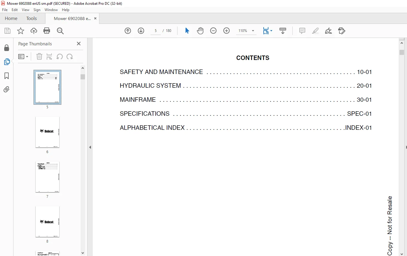
CONTENTS 5
FOREWORD 7
SERIAL NUMBER LOCATION 9
Attachment Serial Number 9
DELIVERY REPORT 9
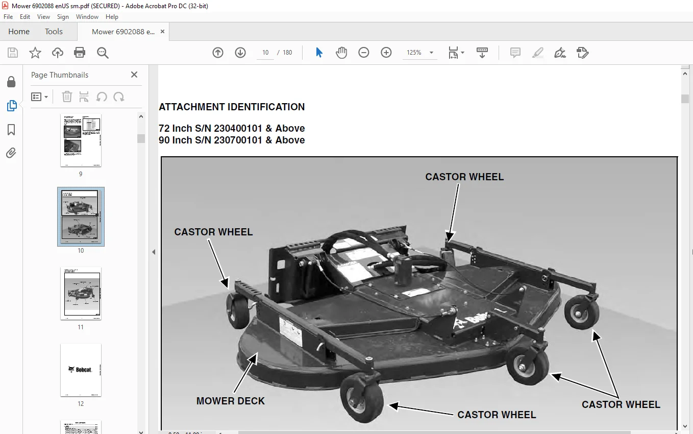
ATTACHMENT IDENTIFICATION 10
72 Inch S/N 230400101 & Above 90 Inch S/N 230700101 & Above 10
72 Inch S/N A8WB00101 & Above 90 Inch S/N A8SD00101 & Above 11
SAFETY & MAINTENANCE 13
TROUBLESHOOTING 15
INSPECTION 17
Bob-Tach 17
Attachment Mounting Frame 19
Mower 19
Checking The Mechanical Linkage (S/N 230400101 & Above, S/N 230700101 & Above) 20
Checking The Mechanical Linkage (S/N A8WB00101 & Above, S/N A8SD00101 & Above) 21
Checking The Blade Shut-off Device (S/N 230400101 & Above, S/N 230700101 & Above) 22
Checking The Blade Shut-off Device (S/N A8WB00101 & Above, S/N A8SD00101 & Above) 23
LUBRICATION 25
Lubrication Locations (S/N 230400101 & Above, S/N 230700101 & Above) 25
Lubrication Locations (S/N A8WB00101 & Above, S/N A8SD00101 & Above) 26
MOWER SERVICE 29
Cleaning The Mower (S/N 230400101 & Above, S/N 230700101 & Above) 29
Cleaning The Mower (S/N A8WB00101 & Above, S/N A8SD00101 & Above) 31
Blade Removal And Installation (S/N 230400101 & Above, S/N 230700101 & Above) 33
Blade Removal And Installation (S/N A8WB00101 & Above, S/N A8SD00101 & Above) 35
Blade Belt Adjustment (S/N 230400101 & Above, S/N 230700101 & Above) 37
Blade Belt Adjustment (S/N A8WB00101 & Above, S/N A8SD00101 & Above) 39
CUTTING HEIGHT 41
Cutting Height Adjustment (S/N 230400101 & Above, S/N 230700101 & Above) 41
Cutting Height Adjustment (S/N A8WB00101 & Above, S/N A8SD00101 & Above) 43
SERVICE SCHEDULE 45
Chart (S/N 230400101 & Above, S/N 230700101 & Above) 45
Chart (S/N A8WB00101 & Above, S/N A8SD00101 & Above) 45
HYDRAULIC SYSTEM 47
HYDRAULIC MOTOR (S/N 230400101 & ABOVE, S/N 230700101 & ABOVE) 49
Removal And Installation 49
Parts Identification 51
Disassembly And Assembly 52
Inspection 55
Timing The Hydraulic Motor 56
HYDRAULIC MOTOR (S/N A8WB00101 & ABOVE, S/N A8SD00101 & ABOVE) 57
Removal And Installation 57
Parts Identification 60
Disassembly And Assembly 61
Inspection 64
Timing The Hydraulic Motor 65
HYDRAULIC CONTROL VALVE (S/N 230700475 & BELOW AND S/N 230401106 & BELOW) 67
Removal And Installation 67
Parts Identification 68
Disassembly 69
Assembly 75
HYDRAULIC CONTROL VALVE (S/N 230700476 & ABOVE AND S/N 230401107 & ABOVE) 83
Removal And Installation 83
Parts Identification 84
Disassembly 85
Assembly 92
HYDRAULIC CONTROL VALVE (S/N A8WB00101 & ABOVE, S/N A8SD00101 & ABOVE) 99
Removal And Installation 99
Parts Identification 100
Disassembly 101
Assembly 108
MAINFRAME 115
BLADE 117
Removal And Installation (S/N 230400101 & Above, S/N 230700101 & Above) 117
Removal And Installation (S/N A8WB00101 & Above, S/N A8SD00101 & Above) 119
CASTER MOUNT AND WHEEL 121
Removal And Installation (S/N 230400101 & Above, S/N 230401107 & Above, S/N 230700101 & Above, S/N 230700476 & Above) 121
Removal And Installation (S/N A8WB00101 & Above, S/N A8SD00101 & Above) 122
MOUNTING FRAME 123
Removal (S/N 230400101 & Above, S/N 230401107 & Above, S/N 230700101 & Above, S/N 230700476 & Above) 123
Installation (S/N 230400101 & Above, S/N 230401107 & Above, S/N 230700101 & Above, S/N 230700476 & Above) 125
Removal (S/N A8WB00101 & Above, S/N A8SD00101 & Above) 126
Installation (S/N A8WB00101 & Above, S/N A8SD00101 & Above) 128
PIVOT BRACKET 129
Removal And Installation 129
BLADE BELT 131
Removal And Installation (S/N 230400101 & Above, S/N 230401107 & Above, S/N 230700101 & Above, S/N 230700476 & Above) 131
Removal And Installation (S/N A8WB00101 & Above, S/N A8SD00101 & Above) 132
BLADE SPINDLE (S/N 230400101 & ABOVE, S/N 230401107 & ABOVE, S/N 230700101 & ABOVE, S/N 230700476 & ABOVE) 135
Removal And Installation 135
Parts Identification 137
Disassembly 138
Assembly 139
BLADE SPINDLE (S/N A8WB00101 & ABOVE, S/N A8SD00101 & ABOVE) 141
Removal And Installation 141
Parts Identification 143
Disassembly 144
Assembly 145
MULCHING KIT (S/N A8WB00101 & ABOVE, S/N A8SD00101 & ABOVE) 147
Removal And Installation 147
SPECIFICATIONS 151
SCHEMATICS 153
Hydraulic Schematic 153
SPECIFICATIONS 155
(72 in ) Dimensions 155
(72 IN ) Performance 157
(72 in ) Hydraulic System 157
(90 in ) Dimensions 158
(90 in ) Performance 160
(90 IN ) Hydraulic System 160
TORQUE SPECIFICATIONS FOR BOLTS 161
Torque For General SAE Bolts 161
Torque For General Metric Bolts 162
HYDRAULIC CONNECTION SPECIFICATIONS 163
O-ring Face Seal Connection 163
Straight Thread O-Ring Fitting 163
Tubelines And Hoses 163
Flare Fitting 164
Port Seal Fitting 164
ALPHABETICAL INDEX 167
SERVICE MANUAL REVISION 169
Revision No: Mower – 1 169
Revision No: Mower – 2 171
Revision No: Mower – 3 173
Revision No: Mower – 4 175
Revision No: Mower – 5 177
Revision No: Mower – 6 179
Questions? Email us: [email protected]
https://vimeo.com/845199694?share=copy
PLEASE NOTE:
- This is the SAME MANUAL used by the dealerships to diagnose your vehicle
- No waiting for couriers / posts as this is a PDF manual and you can download it within 2 minutes time once you make the payment.
- Your payment is all safe and the delivery of the manual is INSTANT – You will be taken to the DOWNLOAD PAGE.
- So have no hesitations whatsoever and write to us about any queries you may have : heydownloadss @gmail.com
S.M