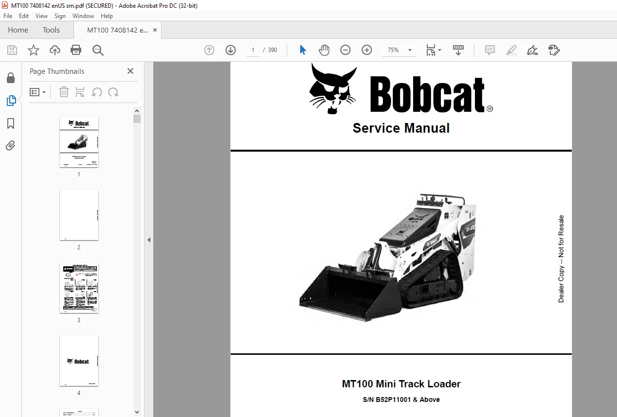
Bobcat MT100 Mini Track Loader Service Manual SN B52P11001 & Above – PDF DOWLOAD
$28.95
Instant English PDF of Bobcat MT100 service manual 7408142 for SN B52P11001 and above. 390 pages covering hydraulics, hydro, tracks, Bob-Tach, Kubota D902-EB engine, electrics and specs.
Description
IMAGES PREVIEW OF THE MANUAL:
This manual is for the Bobcat mini track loader mechanic. It gives the servicing and adjustment procedures for the MT100 and its component parts and systems. Use the Operation & Maintenance Manual for operating instructions, starting procedure and daily checks — that book is a separate publication delivered with the machine.
Safety publications Bobcat expects you to use together
- Delivery Report — confirms complete instructions were given to the new owner and the machine was in safe operating condition
- Operation & Maintenance Manual — operating information plus routine maintenance; stored in the container on the machine; replacements from a Bobcat dealer
- Machine signs (decals) — safe operation and care; locations shown in the O&M manual; replacements from a Bobcat dealer
- Service Manual and Parts Manual — shop-type service and repair work (this PDF is the Service Manual)
Confirm serial B52P11001 and above on the mini track loader plate and the engine serial before you follow a cylinder, pump or head procedure. Earlier MT50 / MT52 / MT55 books are different files.
Why mechanics keep 7408142 on the bench
| Hydraulics with test numbers Lift and tilt cylinders, main and port reliefs, control valve, pump, filter, reservoir and cooler — test, R&I, then disassemble with parts ID. | Hydro, belt and drift Motor and pump overhaul, charge pressure, drive-belt alignment, pump-control and steering-drift adjustment — the usual MT100 travel complaints. | |
| Track carriage in pieces Tension, track R&I, front/rear idlers, tensioner, rollers, sprocket, full carriage and a track-damage identification page. | Kubota D902-EB shop work Injection timing, nozzle pressure, glow plugs, valve clearance, head, crank, pistons and timing gears — not just “remove engine.” |
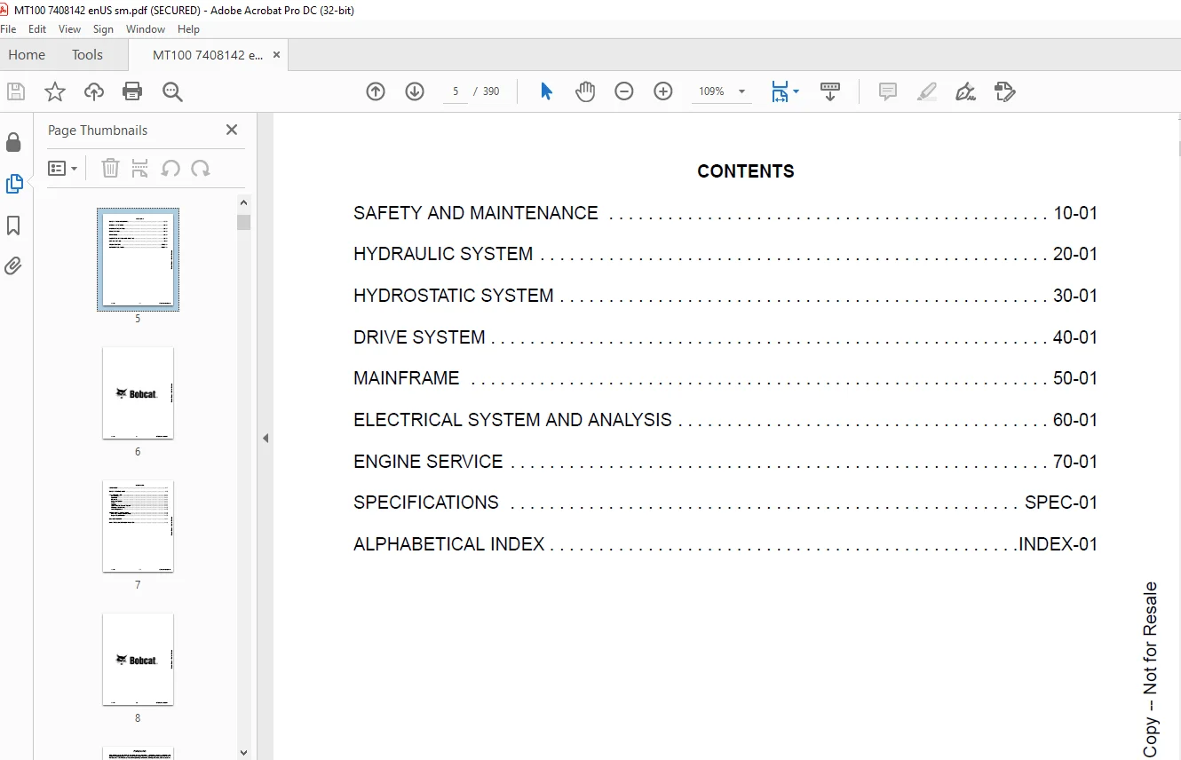
Complete contents
Safety, identification and scheduled maintenance
- Maintenance safety · contents · foreword · safety instructions
- Fire prevention — maintenance, operation, electrical, hydraulic system, fueling, starting, spark-arrester exhaust, welding and grinding, fire extinguishers
- Serial number locations — mini track loader and engine
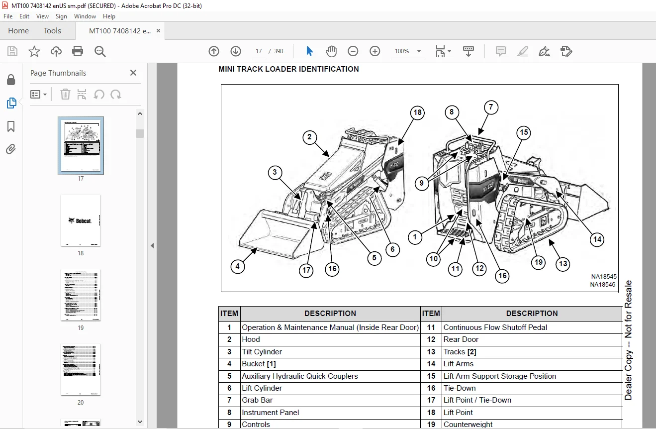
- Delivery report · mini track loader identification
- Lifting and blocking the mini loader — procedure and four-point lift
- Lift-arm support — installing and removing
- Transporting on a trailer — loading, unloading, fastening
- Towing the mini loader
- Service schedule — maintenance intervals
- Air cleaner — replacing filter elements
- Engine cooling — cleaning, checking level, removing and replacing coolant
- Fuel system — specifications, biodiesel blend, filling the tank, fuel filter, removing air
- Engine lubrication — checking/adding oil, oil chart, oil and filter R&R
- Hydraulic / hydrostatic system — checking/adding fluid, fluid chart, filter R&R, fluid R&R, reservoir breather
- Bob-Tach inspection and maintenance · Common Industry Interface inspection and maintenance
- Lubricating the mini loader — locations and parking-brake lubrication
- Spark-arrester muffler cleaning · pivot-pin inspection
- Lift and tilt function lockouts · lift-arm bypass control — operation and inspection
- Neutral-start interlocks — traction-drive and auxiliary-hydraulic interlock inspection
- Auxiliary hydraulic control — inspecting the continuous-flow shutoff pedal
- Counterweights — description, effect on the machine, track-frame vs main-frame upright positions
Hydraulic system
- Hydraulic / hydrostatic schematics
- System information — glossary of hydraulic / hydrostatic symbols and troubleshooting
- Lift cylinder — testing, R&I, parts identification, disassembly and assembly
- Tilt cylinder — testing, R&I, rod-end pivot-pin bushing and seal, parts ID, disassembly and assembly
- Main relief valve — description, testing, R&I
- Port relief valves — lift and tilt testing and R&I
- Hydraulic control valve — description, R&I, identification chart, disassembly and assembly
- Hydraulic pump — direct pump testing, R&I, parts ID, disassembly and assembly
- Hydraulic / hydrostatic filter — description and housing R&I
- Hydraulic fluid reservoir · oil cooler — description and R&I
Hydrostatic system
- Hydrostatic system information — troubleshooting and description
- Hydrostatic motor — description, R&I, parts ID, disassembly, inspection, assembly
- Charge pressure — description, testing, sender R&I, replacing poppet assembly
- Hydrostatic pump — description, R&I, replenishing / high-pressure relief valve, parts ID, disassembly, assembly
- Drive belt — description, shield, adjusting, alignment, belt R&I, tensioner pulley R&I
- Hydrostatic controls — pump-controls D&A, pump-controls adjustment, travel-control lever adjustment, full-forward travel adjustment, steering-drift adjustment
Drive system
- Parking brake — description, handle R&I, cable R&I and adjustment, linkage D&A, brake-pin lubrication
- Track carriage — description, checking and adjusting tension, track R&I
- Front idler and rear idler R&I · tensioner D&A · roller R&I · sprocket R&I · carriage R&I
- Track damage identification
Mainframe
- Bob-Tach — R&I, seal R&I, lever and wedge D&A
- Common Industry Interface (CII) — R&I, seal R&I, lever and wedge D&A
- Lift arms R&I
- Rear door — R&I, latch R&I, bumper adjusting
- Fuel tank R&I · fuel-level sender R&I
- Instrument panel R&I · grab bar R&I
- Hood — R&I, D&A, latch R&I, striker adjusting
- Bottom access panel R&I
- Operator platform R&I · operator cushion · continuous-flow shutoff pedal R&I
Electrical system and analysis
- Electrical schematics
- System information — glossary of electrical symbols, description, fuse and relay location / identification, troubleshooting, solenoid testing
- Battery — maintenance, charge level, storage service, testing, charging, R&I, booster / jump starting
- Alternator — belt adjustment and replacement, description, output test, full-field test, voltage testing, R&I, parts ID
- Starter — testing, R&I, parts ID
- Instrument-panel component R&I
- Neutral-start sensor — description and R&I
- Continuous-flow shutoff system sensor — description, R&I, adjustment, testing
- Electrical / hydraulic controls — identification chart
- Electric cooling fan — description and R&I
Engine service — Kubota® D902-EB
- Engine information — description, specifications, torque values, troubleshooting, engine R&I, mount replacement, compression check
- Engine speed control — R&I, D&A, cable R&I
- Muffler R&I · air-cleaner housing R&I
- Cooling — radiator, fan blade, water pump R&I and D&A, thermostat housing
- Lubrication — oil pan, oil pump R&I and inspection, engine oil-pressure test
- Fuel — fuel camshaft and governor, fuel shutoff solenoid check and installation, injection pump R&I and timing, injector R&I, nozzle pressure, spray condition, valve-seat tightness
- Cylinder head — glow-plug test and R&I, valve-clearance adjustment, valve-timing check, head R&I and D&A, servicing, top clearance, valve guide, reconditioning valve and seat, valve spring, tappets, rocker arm and shaft
- Crankshaft and pistons — piston and rod R&I and servicing, cylinder-bore check, connecting-rod alignment, crankshaft gear, crankshaft and bearings R&I and servicing
- Camshaft and timing gears — timing-gearcase cover, timing-gear backlash, idler gear and shaft, camshaft servicing, idler servicing
- Hydraulic gear-pump mounting bracket and coupler
- Flywheel, ring gear and engine mounting bracket
Specifications, conversions and tools
- Mini track loader specs — narrow-track and wide-track dimensions, performance, controls, engine, hydraulic, electrical, drive, capacities, tracks, ground pressure
- Technical service guide specs — engine, engine torques, cooling, electrical, loader torques, hydraulic system, fuel consumption
- Torque for general SAE and metric bolts
- Hydraulic connection specs — ORFS, straight-thread O-ring, tubelines and hoses, flare, port seal
- Hydraulic fluid specifications
- Conversions — decimal/mm chart and U.S. to metric
- Service tools required — hydraulic tools and engine tools
- Alphabetical index
Who this download is for
- Bobcat dealers and independents working MT100 machines from SN B52P11001 up
- Techs chasing lift/tilt drift, main-relief setting, hydro noise, steering drift or a stretched drive belt
- Shops overhauling a Kubota D902-EB still in the loader frame or on the stand
- Owners who want the factory service schedule, track-tension procedure and interlock inspections in one file
Please note
This is the same class of manual dealers use to troubleshoot the machine. It can be yours within minutes after payment. Questions or a different Bobcat book? Write to [email protected].
Never service the MT100 without instructions
Install the lift-arm support before you work under a raised arm. Relieve hydraulic pressure. Support the machine before track or carriage work. Follow fire-prevention rules for welding, fueling and the spark-arrester muffler. This listing is a digital copy of Bobcat MT100 service manual 7408142 for SN B52P11001 and above.
Download the MT100 service manual now
Add to cart, check out, and receive the English PDF immediately — 390 pages of factory service procedures for the Bobcat MT100 mini track loader. Print the cylinder, track or D902 chapter. Keep the schematics on the shop PC.
Search terms: Bobcat MT100 service manual PDF, MT100 B52P11001 workshop manual, 7408142 service manual download, Bobcat MT100 hydraulic schematic, MT100 hydrostatic pump motor, Kubota D902-EB loader engine service, Bobcat mini track loader Bob-Tach CII repair manual.