Bobcat MT50 Mini Track Loader Service Manual 6901510 (6-12) – PDF DOWNLOAD
$29.95
Bobcat MT50 Mini Track Loader Service Manual 6901510 (6-12) – PDF DOWNLOAD
S/N 520611001 & Above
S/N 522411001 & Above
Description
Bobcat MT50 Mini Track Loader Service Manual 6901510 (6-12) – PDF DOWNLOAD
FILE DETAILS:
Bobcat MT50 Mini Track Loader Service Manual 6901510 (6-12) – PDF DOWNLOAD
Language : English
Pages : 456
Downloadable : Yes
File Type : PDF
IMAGES PREVIEW OF THE MANUAL:
DESCRIPTION:
Bobcat MT50 Mini Track Loader Service Manual 6901510 (6-12) – PDF DOWNLOAD
S/N 520611001 & Above
S/N 522411001 & Above
FOREWORD:
This manual is for the Bobcat loader mechanic. It provides necessary servicing and adjustment procedures for the Bobcat Mini loader and its component parts and systems. Refer to the Operation & Maintenance manual for operating instructions, Starting procedure, daily checks, etc.
SAFETY INSTRUCTIONS:
The following publications provide information on the safe use and maintenance of the Bobcat machine and attachments:
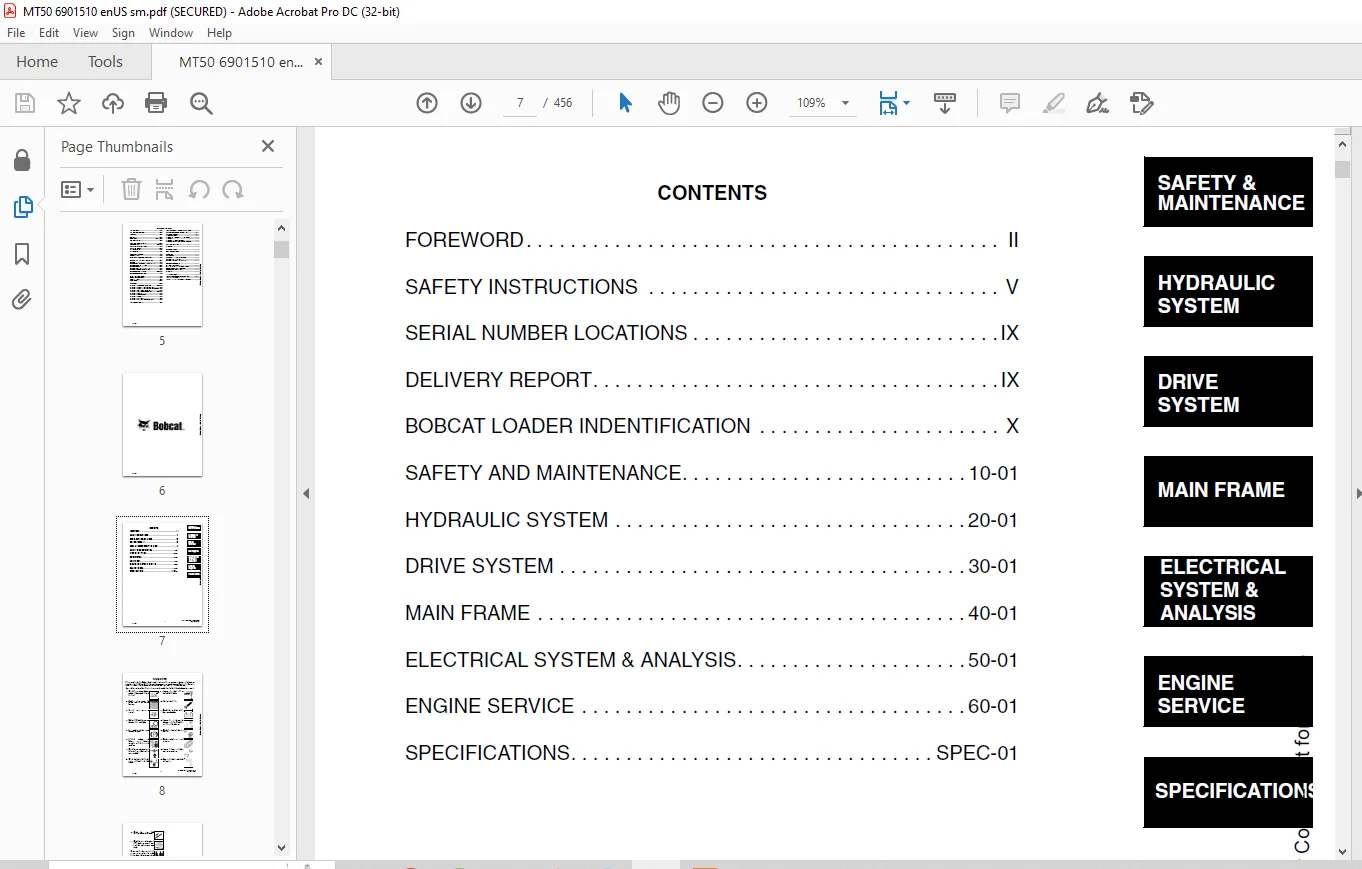
TABLE OF CONTENTS:
Bobcat MT50 Mini Track Loader Service Manual 6901510 (6-12) – PDF DOWNLOAD
MAINTENANCE SAFETY 3
ALPHABETICAL INDEX 5
CONTENTS 7
FOREWORD 8
SAFETY INSTRUCTIONS 11
Fire Prevention 13
SERIAL NUMBER LOCATIONS 15
Loader Serial Number 15
Engine Serial Number 15
DELIVERY REPORT 15
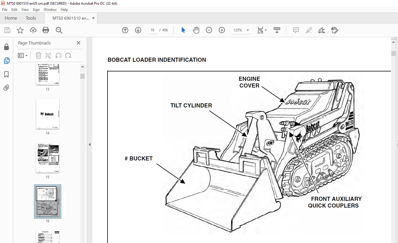
BOBCAT LOADER INDENTIFICATION 16
SAFETY AND MAINTENANCE 17
LIFTING AND BLOCKING THE LOADER 19
Procedure 19
Four Point Lift 20
LIFT ARM SUPPORT DEVICE 21
Installing Lift Arm Support Device 21
Removing Lift Arm Support Device 21
TRANSPORTING THE BOBCAT LOADER 23
Procedure 23
TOWING THE LOADER 25
Procedure 25
SERVICE SCHEDULE 27
Chart 27
AIR CLEANER SERVICE 29
Replacing the Filter Element 29
ENGINE COOLING SYSTEM 31
Checking The Coolant Level 31
Cleaning The Cooling System 31
Replacing The Coolant 32
FUEL SYSTEM 33
Fuel Specifications 33
Filling The Fuel Tank 33
Fuel Filter 34
Removing Air From The Fuel System 34
ENGINE LUBRICATION SYSTEM 35
Checking Engine Oil 35
Oil Chart 35
Replacing Oil And Filter 35
HYDRAULIC SYSTEM 39
Checking And Adding Fluid 39
Replacing Hydraulic Filter 39
Hydraulic Breather Cap 39
Replacing Hydraulic Fluid 39
BOB-TACH 41
Inspection and Maintenance 41
LUBRICATION OF THE BOBCAT LOADER 43
Procedure 43
Pivot Pins 44
SPARK ARRESTOR MUFFLER 45
Servicing 45
HYDRAULIC SYSTEM 47
HYDRAULIC SCHEMATICS 51
HYDRAULIC SYSTEM INFORMATION 57
Workgroup Troubleshooting Chart 61
Hydraulic Function Troubleshooting 62
Hydraulic Drive Troubleshooting Chart 63
CYLINDER (LIFT) 65
Checking The Lift Cylinder(s) 65
Removal And Installation 65
Parts Identification 67
Disassembly And Assembly 68
CYLINDER (TILT) 71
Checking The Tilt Cylinder 71
Removal And Installation 71
Parts Identification 73
Disassembly And Assembly 74
MAIN RELIEF VALVE 77
Checking (Workgroup Hydraulic Control Valve) 77
Removal And Installation (Workgroup Hydraulic Control Valve) 79
Checking (Left Drive) 79
Adjustment (Left Drive) 81
Removal And Installation (Left Drive) 82
Checking (Right Drive) 83
Adjustment (Right Drive) 84
Removal And Installation (Right Drive) 85
PORT RELIEF VALVE 87
Checking The Port Relief Valves (Lift) 87
Adjusting The Port Relief Valves (Lift) 88
Removal And Installation (Lift) 89
Checking The Port Relief Valves (Tilt) 90
Adjusting The Port Relief Valves (Tilt) 91
Removal And Installation (Tilt) 92
HYDRAULIC CONTROL VALVE (DRIVE) 93
Removal And Installation 93
Disassembly 99
Assembly 117
HYDRAULIC CONTROL VALVE (WORK GROUP) 135
Removal And Installation 135
Disassembly 137
Assembly 159
HYDRAULIC PUMP (ALUMINMUM) (S/N 520611905 & Below) 179
Check The Output Of The Hydraulic Pump 179
Removal And Installation 180
Coupler Removal And Installation 181
Parts Identification 182
Disassembly And Assembly 183
Inspection 188
HYDRAULIC PUMP (CAST IRON) (S/N 520611906 & above) 189
Check The Output Of The Hydraulic Pump 189
Removal And Installation 191
Parts Identification 192
Disassembly And Assembly 193
HYDRAULIC FILTER 197
Housing Removal And Installation 197
HYDRAULIC FLUID RESERVOIR 199
Removal And Installation 199
DRIVE MOTOR 201
Removal And Installation 201
Parts Identification 203
Disassembly 204
Inspection 210
Assembly 212
COUNTERBALANCE VALVE 221
Removal And Installation 221
Disassembly And Assembly 222
SPEED CONTROL VALVE 223
Removal And Installation (S/N 520612036 & Below) 223
Removal And Installation (S/N 520612036 & Below) (Cont’d) 224
SPEED CONTROL VALVE 225
Removal And Installation (S/N 520612037 & Above) 225
Removal And Installation (S/N 520612037 & Above) (Cont’d) 226
Parts Identification 227
Disassembly And Assembly 228
SINGLE INLET MODE SELECT VALVE 231
Removal And Installation (S/N 520612036 & Below) 231
Parts Identification (S/N 520612036 & Below) 232
Disassembly And Assembly (S/N 520612036 & Below) 233
Removal And Installation (S/N 520612037 & Above) 236
Parts Identification (S/N 520612037 & Above) 237
Disassembly And Assembly (S/N 520612037 & Above) 238
DUAL INLET MODE SELECT VALVE 241
Removal And Installation (S/N 520612036 & Below) 241
Parts Identification (S/N 520612036 & Below) 242
Removal And Installation (S/N 520612037 & Above) 246
Parts Identification (S/N 520612037 & Above) 247
LIFT LOCK VALVE 251
Solenoid Testing 251
Solenoid Removal And Installation 251
Removal And Installation 252
Disassembly And Assembly 253
TILT LOCK VALVE 255
Solenoid Testing 255
Solenoid Removal And Installation 255
Removal And Installation 256
Disassembly And Assembly 257
REVERSE SPEED LIMIT VALVE 259
Removal and Installation 259
Disassembly and Assembly 260
HYDRAULIC OIL COOLER 263
Removal And Installation 263
DRIVE SYSTEM 267
PARKING BRAKE 269
Handle Removal And Installation 269
Cable Removal And Installation 269
Cable Adjustment 270
Pin Lubrication 271
DRIVE COMPONENTS 273
Track Tension 273
Adjusting The Tracks 273
Track Removal and Installation 274
Track Idler Removal and Installation 275
Parts Identification (Track Idler) 276
Track Idler Disassembly and Assembly 277
Track Tensioner Disassembly and Assembly 278
Track Roller Removal and Installation 278
Parts Identification (Track Roller) 279
Track Roller Disassembly and Assembly 280
Track Frame Removal and Installation 280
Track Damage Identification 282
LEFT AND RIGHT TRAVEL ADJUSTMENT 293
Description 293
Adjustment (S/N 520611001 thru 520611064, 520611066, 520611068 thru 520611072, 520611074 thru 520611080, 520611082 thru 520611085, 520611087, 520611088, 520611090, 520611091, 520611093, 520611095, 520611096, 520611098, 520611100 thru 52061110 293
Adjustment (S/N 520611065, 520611067, 520611073, 520611081, 520611086, 520611089, 520611092, 520611094, 520611097, 520611099 thru 520611105, 520611107 thru 520611118, 520611120 thru 520611129) 295
MAIN FRAME 297
BOB-TACH 299
Removal 299
Installation 300
Seal Removal And Installation 301
Lever And Wedge Removal 301
LIFT ARM 303
Removal And Installation 303
REAR DOOR 305
Removal And Installation 305
FUEL TANK 307
Removal And Installation 307
CONTROL PANEL PLATE 309
Removal and Installation 309
HAND BAR 311
Removal and Installation 311
Adjustment 311
ENGINE COVER 313
Removal and Installation 313
Disassembly And Assembly 313
COUNTERWEIGHT 315
Removal And Installation 315
REVERSE STOP PANEL 317
Description 317
Inspecting Function 317
Adjusting 317
Removal And Installation 318
ELECTRICAL SYSTEM & ANALYSIS 319
ELECTRICAL SCHEMATICS 321
ELECTRICAL SYSTEM INFORMATION 325
Electrical Troubleshooting Chart 325
BATTERY 327
Removal and Installation 327
Servicing 328
Using A Booster Battery (Jump Starting) 328
ALTERNATOR 331
Removal and Installation (S/N 520611001-520611125) 331
Removal and Installation (S/N 520611126 & Above) 331
ALTERNATOR (CONT’D) 332
Adjusting The Alternator Belt 332
Description 333
Tests 334
Alternator Output Test 334
Full Field Test 334
Alternator Regulator Test 335
Alternator Regulator Test Using Voltmeter 335
STARTER 337
Removal And Installation 337
Checking The Starter In The Loader 338
Parts Identification 339
Disassembly 340
Inspection And Repair 345
No Load Test 349
Assembly 350
INSTRUMENT PANEL 357
Removal And Installation 357
Disassembly And Assembly 357
BLOWER ASSEMBLY 359
Removal And Installation 359
Parts Identification 361
Disassembly And Assembly 362
ELECTRICAL ATTACHMENT CONTROL REFERENCE 363
Attachment Control Identification Chart 363
ENGINE SERVICE 365
ENGINE INFORMATION AND TESTING 367
Engine Troubleshooting Chart 367
ENGINE SPEED CONTROL 369
Removal And Installation 369
Disassembly And Assembly 369
Cable Removal and Installation 369
MUFFLER 371
Removal And Installation 371
AIR CLEANER 373
Housing Removal and Installation 373
RADIATOR 375
Removal And Installation 375
ENGINE COMPONENTS AND TESTING 377
Valve Clearance Adjustment 377
Fuel Injection Pump Check 378
Fuel Lift Pump Removal And Installation 378
Fuel Injection Pump Removal And Installation 379
Fuel Injection Pump Timing 380
Fuel Injector Nozzles Checking 381
Fuel Injector Nozzles Removal 382
Fuel Injector Nozzles Installation 383
Glow Plugs Checking 384
Engine Compression Test Procedure 384
ENGINE 385
Removal And Installation 385
Engine Mount Replacement 388
FRONT ENGINE MOUNT 391
Removal and Installation 391
SIDE ENGINE MOUNTS 393
Removal and Installation 393
FLYWHEEL AND HOUSING 395
Flywheel Removal And Installation 395
Hydraulic Pump Coupler Removal And Installation (Early Version) 395
Hydraulic Pump Coupler Removal And Installation (Later Version) 396
Flywheel Ring Gear 396
RECONDITIONING THE ENGINE 397
Cylinder Head Removal And Installation 397
Cylinder Head Inspection 398
Cylinder Head Top Clearance 399
Rocker Arm And Shaft Checking 399
Valve Removal 400
Valve Spring Checking 401
Valve Guide Checking 402
Reconditioning The Valve And Valve Seat 403
Timing Gearcase Cover Removal And Installation 404
Idler Gear And Camshaft Removal And Installation 406
Servicing The Idler Gear And Shaft 408
Checking Timing Gear Backlash 409
Fuel Camshaft Removal And Installation 410
Governor 410
Crankshaft Gear Removal And Installation 411
Oil Pump Removal And Installation 411
Oil Pump Service 411
Checking Engine Oil Pressure 412
Relief Valve 412
Piston And Connecting Rod Removal And Installation 413
Piston And Connecting Rod Servicing 415
Connecting Rod Alignment 416
Crankshaft And Bearings Removal And Installation 417
Inspection Of Crankshaft And Bearings 418
Cylinder Bore Inspection 420
Thermostat Removal And Installation 421
Testing The Thermostat 421
Water Pump Removal And Installation 422
Water Pump Disassembly And Assembly 422
SPECIFICATIONS 423
LOADER SPECIFICATIONS (MT50) 425
Loader Dimensions 425
Performance 426
Controls 426
Engine 426
Hydraulic System 427
Electrical 427
Drive System 427
Capacities 428
Tracks 428
Ground Pressure 428
ENGINE SPECIFICATIONS 429
Engine 429
Fuel Injector Nozzles 429
Fuel Injection Pump 429
Cylinder Head 429
Valves 429
Valve Springs 429
Rocker Arms 430
Camshaft 430
Cylinders 430
Piston Rings 430
Pistons 431
Crankshaft 431
Oil Pump 431
Thermostat 431
Engine Bolt Torque 432
Re-Grinding The Crankshaft 433
LOADER TORQUE 435
Specifications 435
TORQUE SPECIFICATIONS FOR BOLTS 437
Torque For General SAE Bolts 437
Torque For General Metric Bolts 438
Torque For Kubota Metric Engine Bolts 439
HYDRAULIC CONNECTION SPECIFICATIONS 441
O-ring Face Seal Connection 441
Straight Thread O-ring Fitting 442
Tubelines And Hoses 442
Flare Fitting 442
O-ring Flare Fitting 443
Port Seal Fitting 445
HYDRAULIC FLUID SPECIFICATIONS 447
Specifications 447
CONVERSIONS 449
Decimal And Millimeter Equivalents 449
SMR 451
Revision No: MT50-1 451
Revision No: MT50-2 453
Revision No: MT50-3 455
Need help? Contact: [email protected]
PLEASE NOTE:
- This is the same manual used by the dealers to diagnose and troubleshoot your vehicle
- You will be directed to the download page as soon as the purchase is completed. The whole payment and downloading process will take anywhere between 2-5 minutes
- Need any other service / repair / parts manual, please feel free to contact [email protected] . We still have 50,000 manuals unlisted
S.V


