Bobcat MT52 & MT55 Mini Track Loader Service Manual 6903372 (10-12) – PDF DOWNLOAD
$29.95
Bobcat MT52 & MT55 Mini Track Loader Service Manual 6903372 (10-12) – PDF DOWNLOAD
S/N 528711001 & Above
S/N 528811001 & Above
S/N 538711001 & Above
S/N 538811001 & Above
Description
Bobcat MT52 & MT55 Mini Track Loader Service Manual 6903372 (10-12) – PDF DOWNLOAD
FILE DETAILS:
Bobcat MT52 & MT55 Mini Track Loader Service Manual 6903372 (10-12) – PDF DOWNLOAD
Language : English
Pages : 402
Downloadable : Yes
File Type : PDF
IMAGES PREVIEW OF THE MANUAL:
DESCRIPTION:
Bobcat MT52 & MT55 Mini Track Loader Service Manual 6903372 (10-12) – PDF DOWNLOAD
S/N 528711001 & Above
S/N 528811001 & Above
S/N 538711001 & Above
S/N 538811001 & Above
FOREWORD:
This manual is for the Bobcat loader mechanic. It provides necessary servicing and adjustment procedures for the Bobcat Mini loader and its component parts and systems. Refer to the Operation & Maintenance manual for operating instructions, Starting procedure, daily checks, etc.
SAFETY INSTRUCTIONS:
The following publications provide information on the safe use and maintenance of the Bobcat machine and attachments:
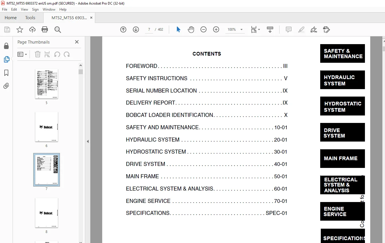
TABLE OF CONTENTS:
Bobcat MT52 & MT55 Mini Track Loader Service Manual 6903372 (10-12) – PDF DOWNLOAD
MAINTENANCE SAFETY 3
ALPHABETICAL INDEX 5
CONTENTS 7
FOREWORD 9
SAFETY INSTRUCTIONS 11
Fire Prevention 13
SERIAL NUMBER LOCATION 15
Loader Serial Number 15
Engine Serial Number 15
DELIVERY REPORT 15
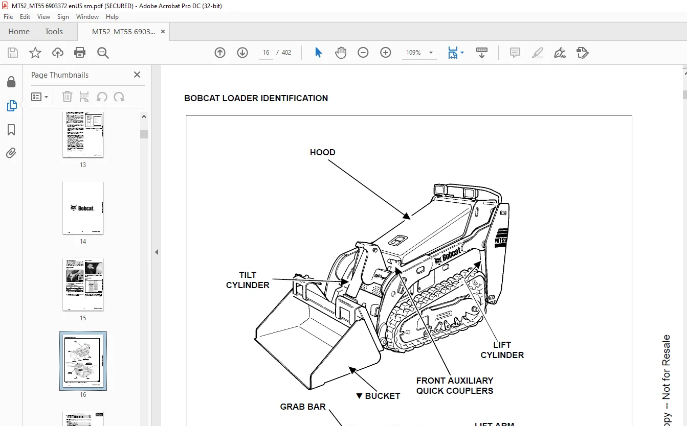
BOBCAT LOADER IDENTIFICATION 16
SAFETY AND MAINTENANCE 17
LIFTING AND BLOCKING THE LOADER 19
Procedure 19
Four Point Lift 20
LIFT ARM SUPPORT DEVICE 21
Installing 21
Removing 21
TRANSPORTING THE BOBCAT LOADER 23
Procedure 23
TOWING THE LOADER 25
Procedure 25
SERVICE SCHEDULE 27
Chart 27
AIR CLEANER SERVICE 29
Replacing The Filter Elements (Early Models) 29
Replacing The Filter Elements (Later Models) 30
ENGINE COOLING SYSTEM 31
Checking The Coolant Level 31
Cleaning The Cooling System 32
Replacing The Coolant 32
FUEL SYSTEM 35
Fuel Specifications 35
Filling The Fuel Tank 35
Fuel Filter 36
Removing Air From The Fuel System 36
ENGINE LUBRICATION SYSTEM 39
Checking Engine Oil 39
Oil Chart 39
Replacing Oil And Filter 39
HYDRAULIC / HYDROSTATIC SYSTEM 41
Checking And Adding Fluid 41
Replacing Hydraulic Filter 41
Hydraulic Reservoir Breather 41
Replacing Hydraulic Fluid 42
BOB-TACH 43
Inspection And Maintenance 43
LUBRICATION OF THE BOBCAT MINI LOADER 45
Procedure 45
Parking Brake Lubrication 46
Pivot Pins 47
SPARK ARRESTOR MUFFLER 49
Servicing 49
CONTROLS 51
Reverse Stop Panel 51
Lift And Tilt Function Lockouts 51
Lift Arm By-Pass Controls 51
Neutral Start Interlocks 52
ELECTRICAL SYSTEM 53
Description 53
Fuse And Relay Location / Identification 53
Cleaning Battery Terminals 54
Using A Booster Battery (Jump Starting) 55
Removing And Installing The Battery 56
HYDRAULIC SYSTEM 57
HYDRAULIC/HYDROSTATIC SCHEMATICS 59
HYDRAULIC SYSTEM INFORMATION 63
Workgroup Troubleshooting Chart 67
Hydraulic Function Troubleshooting 68
CYLINDER (LIFT) 69
Checking The Lift Cylinder(s) 69
Removal And Installation 70
Parts Identification 71
Disassembly And Assembly 72
CYLINDER (TILT) 75
Checking The Tilt Cylinder 75
Removal And Installation 76
Rod End Pivot Pin Bushing And Seal Replacement 77
Parts Identification 78
Disassembly And Assembly 79
MAIN RELIEF VALVE 81
Checking 81
Removal And Installation 83
PORT RELIEF VALVES 85
Checking The Port Relief Valves (Lift) 85
Removal And Installation (Lift) 87
Checking The Port Relief Valves (Tilt) 88
Removal And Installation (Tilt) 90
HYDRAULIC CONTROL VALVE 93
Removal And Installation 93
Parts Identification 96
Identification Chart 98
Disassembly and Assembly 99
HYDRAULIC PUMP 117
Check The Output Of The Hydraulic Pump 117
Removal And Installation 119
Parts Identification 120
Disassembly And Assembly 121
HYDRAULIC FILTER 123
Housing Removal And Installation 123
HYDRAULIC FLUID RESERVOIR 125
Removal And Installation 125
HYDRAULIC OIL COOLER 127
Removal And Installation 127
HYDROSTATIC SYSTEM 129
HYDROSTATIC SYSTEM INFORMATION 131
Troubleshooting Chart 131
Replenishing Valve Function 132
DRIVE MOTOR 133
Removal And Installation 133
Parts Identification 136
Disassembly 137
Inspection 143
Assembly 145
HYDROSTATIC PUMP 151
Charge Pressure Sender Removal And Installation 151
Checking Charge Pressure 151
Replacing Poppet Assembly 151
Removal And Installation 152
Replenishing/High Pressure Relief Valve 153
Disassembly 154
Assembly 160
DRIVE BELT 167
Removing Drive Belt Shield 167
Adjusting The Drive Belt Tension 167
Drive Belt Replacement 168
Tensioner Pulley Removal And Installation 169
Drive Belt Alignment 169
HYDROSTATIC CONTROLS (S/N 528711001 – 528712699, S/N 528811001 – 528811149 AND S/N 538711001 – 538712499) 171
Steering Assembly Identification 171
Steering Assembly Removal And Installation 172
Steering Linkage Adjustment 174
Adjusting Forward Speed Control 178
Adjusting Reverse Speed Control 179
HYDROSTATIC CONTROLS (S/N 528712700 & ABOVE, S/N 528811150 & ABOVE AND S/N 538712500 & ABOVE) 181
Steering Assembly Identification 181
Steering Assembly Removal And Installation 182
Steering Linkage Adjustment 184
Adjusting Reverse Speed Control 188
DRIVE SYSTEM 189
PARKING BRAKE 191
Handle Removal And Installation 191
Cable Removal And Installation 191
Cable Adjustment 192
Removing The Linkage Assembly 193
Brake Pin Lubrication 194
DRIVE COMPONENTS 195
Track Tension Checking 195
Adjusting The Tracks 195
Track Removal and Installation 196
Track Frame Removal and Installation 197
Rear Idler Assembly Removal and Installation 198
Parts Identification (Rear Track Idler) 199
Rear Idler Disassembly and Assembly 200
Front Idler Disassembly And Assembly 201
Track Tensioner Disassembly and Assembly 202
Track Roller Removal and Installation 202
Parts Identification (Track Roller) 203
Track Roller Disassembly and Assembly 204
Track Damage Identification 205
MAIN FRAME 215
BOB-TACH 217
Removal 217
Installation 218
Seal Removal And Installation 219
Lever And Wedge Removal 219
LIFT ARM 221
Removal And Installation 221
TAILGATE 223
Removal And Installation 223
Rear Door Panel Removal And Installation 223
Tailgate Striker Removal And Installation 224
Tailgate Striker Adjustment 224
Tailgate Bumper Adjustment 225
FUEL TANK 227
Removal And Installation 227
INSTRUMENT PANEL 229
Removal and Installation 229
GRAB BAR 231
Removal and Installation 231
HOOD 233
Removal and Installation 233
Disassembly And Assembly 233
Hood Latch Removal 234
REVERSE STOP PANEL 235
Description 235
Inspecting Function 235
Removal And Installation 235
Reverse Stop Mechanism Removal And Installation 236
BOTTOM ACCESS PANEL 237
Removal and Installation 237
RIDE-ON PLATFORM 239
Removal and Installation 239
Tire Removal and Installation 239
Caster Removal and Installation 240
ELECTRICAL SYSTEM & ANALYSIS 241
ELECTRICAL SCHEMATICS 243
ELECTRICAL SYSTEM INFORMATION 245
Electrical Troubleshooting Chart 245
BATTERY 247
Removal and Installation 247
Servicing 248
Using A Booster Battery (Jump Starting) 248
ALTERNATOR 251
Removal and Installation 251
Adjusting The Alternator Belt 252
Description 252
Tests 252
Alternator Output Test 253
Full Field Test 253
Alternator Regulator Test 254
Alternator Regulator Test Using Voltmeter 254
STARTER 255
Removal And Installation 255
Checking The Starter In The Loader 256
Parts Identification 257
Disassembly 258
Inspection And Repair 263
No Load Test 267
Assembly 268
INSTRUMENT PANEL 275
Component Removal And Installation 275
NEUTRAL START SENSOR (S/N 528711001 – 528712429, S/N 528811001 – 528811121 AND S/N 538711001 – 538712295) 277
Description 277
Removal And Installation 277
Sensor Activation Adjustment 278
Sensor Activation Bolt Removal 278
NEUTRAL START SENSOR (S/N 528712430 & aBOVE, S/N 528811122 & ABOVE AND S/N 538712296 & ABOVE) 279
Description 279
Removal And Installation 279
Sensor Activation Adjustment 280
Sensor Activation Bolt Removal 281
ELECTRICAL ATTACHMENT CONTROL REFERENCE 283
Attachment Control Identification Chart 283
ENGINE SERVICE 285
ENGINE INFORMATION AND TESTING 287
Engine Troubleshooting Chart 287
ENGINE SPEED CONTROL 289
Removal And Installation 289
Disassembly And Assembly 290
Cable Removal and Installation 290
MUFFLER 293
Removal And Installation 293
AIR CLEANER 295
Housing Removal and Installation 295
RADIATOR 297
Removal And Installation 297
ENGINE COMPONENTS AND TESTING 301
Valve Clearance Adjustment 301
Fuel Injection Pump Check 302
Fuel Lift Pump Removal And Installation 303
Fuel Injection Pump Removal And Installation 303
Fuel Injector Nozzles Checking 305
Fuel Injector Nozzles Removal 307
Fuel Injector Nozzles Installation 308
Glow Plugs Checking 308
Engine Compression Test Procedure 308
Fuel Injection Pump Timing 309
ENGINE (S/N 528711001 – 528712699, S/N 528811001 – 528811149 AND S/N 538711001 – 538712499) 311
Removal And Installation 311
Engine Mount Replacement 315
ENGINE (S/N 528712700 & ABOVE, S/N 528811150 & above AND S/N 538712500 & ABOVE) 317
Removal And Installation 317
Engine Mount Replacement 321
FLYWHEEL 323
Flywheel Removal And Installation 323
Flywheel Ring Gear Removal And Installation 323
RECONDITIONING THE ENGINE 325
Cylinder Head Removal And Installation 325
Cylinder Head Inspection 326
Cylinder Head Top Clearance 327
Rocker Arm And Shaft Checking 327
Valve Removal 328
Valve Spring Checking 329
Valve Guide Checking 330
Reconditioning The Valve And Valve Seat 331
Timing Gearcase Cover Removal And Installation 332
Idler Gear And Camshaft Removal And Installation 334
Servicing The Idler Gear And Shaft 336
Checking Timing Gear Backlash 337
Fuel Camshaft Removal And Installation 338
Governor 338
Crankshaft Gear Removal And Installation 339
Oil Pump Removal And Installation 339
Oil Pump Service 339
Checking Engine Oil Pressure 340
Relief Valve 340
Piston And Connecting Rod Removal And Installation 341
Piston And Connecting Rod Servicing 343
Connecting Rod Alignment 345
Crankshaft And Bearings Removal And Installation 345
Inspection Of Crankshaft And Bearings 348
Cylinder Bore Inspection 350
Thermostat Removal And Installation 350
Testing The Thermostat 351
Water Pump Removal And Installation 351
Water Pump Disassembly And Assembly 352
Energize To Stop Solenoid 352
ENGINE MOUNTING BRACKET 353
Engine Mounting Bracket Removal And Installation 353
HYDRAULIC GEAR PUMP MOUNTING BRACKET 355
Hydraulic Gear Pump Mounting Bracket Removal And Installation 355
Hydraulic Gear Pump Coupler Removal And Installation 356
SPECIFICATIONS 357
LOADER SPECIFICATIONS 359
Loader Dimensions (MT52) 359
Loader Dimensions (MT55) 360
Performance 361
Controls 361
Engine 361
Hydraulic System 362
Electrical 362
Drive System 362
Capacities 363
Tracks 363
Ground Pressure 363
ENGINE SPECIFICATIONS (KUBOTA D902-E2B) 365
Engine 365
Fuel Injector Nozzles 365
Fuel Injection Pump 365
Cylinder Head 365
Valves 365
Valve Springs 365
Rocker Arms 366
Camshaft 366
Cylinders 366
Piston Rings 366
Pistons 367
Connecting Rods 367
Crankshaft 367
Oil Pump 367
Timing Gear 368
Thermostat 368
Engine Bolt Torque 369
ENGINE SPECIFICATIONS (KUBOTA D722-E2B) 371
Engine 371
Fuel Injector Nozzles 371
Fuel Injection Pump 371
Cylinder Head 371
Valves 371
Valve Springs 371
Rocker Arms 372
Camshaft 372
Cylinders 372
Piston Rings 372
Pistons 373
Connecting Rods 373
Crankshaft 373
Oil Pump 373
Timing Gear 374
Thermostat 374
Engine Bolt Torque 375
TORQUE SPECIFICATIONS FOR BOLTS 377
Torque For General SAE Bolts 377
Torque For General Metric Bolts 378
Torque For Kubota Metric Engine Bolts 379
HYDRAULIC CONNECTION SPECIFICATIONS 381
O-ring Face Seal Connection 381
Straight Thread O-ring Fitting 382
Tubelines And Hoses 382
Flare Fitting 382
O-ring Flare Fitting 383
Port Seal Fitting 385
HYDRAULIC FLUID SPECIFICATIONS 387
Specifications 387
CONVERSIONS 389
Decimal And Millimeter Equivalents 389
U S To Metric Conversion 389
SMR 391
MT52, MT55-1 391
MT52, MT55-2 393
MT52, MT55-3 395
MT52, MT55-4 397
MT52, MT55-5 399
MT52, MT55-6 401
Customer Support: [email protected]
PLEASE NOTE:
- This is the same manual used by the DEALERSHIPS to SERVICE your vehicle.
- The manual can be all yours – Once payment is complete, you will be taken to the download page from where you can download the manual. All in 2-5 minutes time!!
- Need any other service / repair / parts manual, please feel free to contact us at heydownloadss @gmail.com . We may surprise you with a nice offer
S.V